Flow over an airfoil
Aim:- To simulate the flow over a NACA0017 airfoil for the angle of attacks 0,2,4,6,8,10 and compare the lift and drag forces.
Theory:-
An airfoil or aerofoil is the cross-sectional shape of a wing, blade of a propeller, rotor, turbine. An airfoil-shaped body moving through a fluid produces an aerodynamic forces. The component of this force perpendicular to the direction of motion is called lift. The component parallel to the direction of motion is called drag. Subsonic flights airfoils have a characteristic shape with a rounded leading edge, followed by a sharp trailing edge, often with a symmetric curvature of upper and lower surfaces.
Airfoils are highly-efficient lifting shapes, able to generate more lift than similarly sized flat plates of the same area, and able to generate lift with significantly less drag.
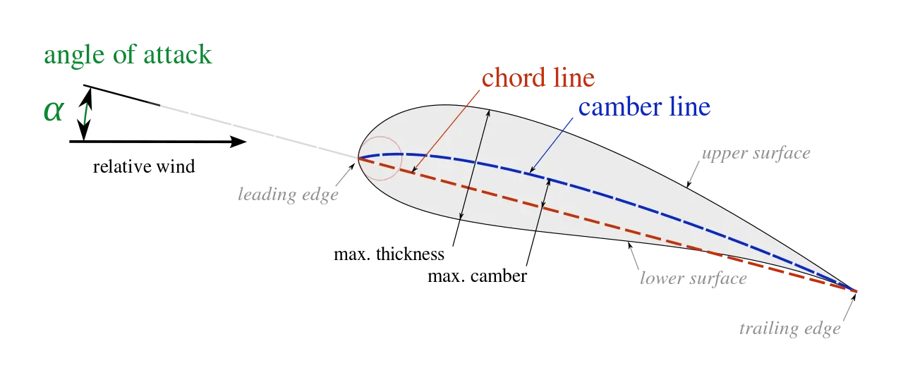
The digits in NACA's four digit numbering system are defined as follows:
The first digit denotes the maximum camber, Cmax, as a percent of the chord;
The second digit denotes the chordwise position of the maximum camber, XCmax, in tenths of the chord;
The last two digits denotes the maximum thickness of the airfoil section, t, as a percent of the chord.
Procedure of simulation:-
1. The modelling airfoil is done by importing the data file containing airfoil cross-section x, y, z co-ordinates using 'curve through XYZ points'. And then its rotated to required AOA and extruded.
2. In wizard option of Flow simulation tab the parameters are set as: Time-dependent option, Air is selected as fluid, Velocity in x-direction=600 m/s. Then the computational domain is set. And default basic mesh is used with local mesh refinement at surface of airfoil.
3. Since the calculation domain is large, the solution takes time. Thus to get the point of convergence we define global and surface goals. We stop the solution when the force on the surface in the x and y-direction reach a stable value.
Results:-
Case 1:- Angle of attack = 0deg.
Solver window
Lift and drag force convergence
Velocity distribution
Case 2:- Angle of attack = 2deg.
Solver window
Lift and drag force convergence
Velocity distribution
Case 3:- Angle of attack = 4deg.
Solver window
Lift and drag force convergence
Velocity distribution
Case 4:- Angle of attack = 6deg.
Solver window
Lift and drag force convergence
Velocity distribution
Case 5:- Angle of attack = 8deg.
Solver window
Lift and drag force convergence
Velocity distribution
Case 6:- Angle of attack = 10deg.
Solver window
Lift and drag force convergence
Velocity distribution
Conclusion:-
We can observe that as the angle of attack increases drag force increases prabolically and lift force increases linearly. As the drag force increases rapidly after particular angle a suitable angle of attack should be considered while designing the airfoil.