Flow over an airfoil
flow over NACA-0017 airfoil
Aim:- Perform flow simulation on a NACA-0017 airfoil with 0,2,4,6,8,10 angle and compare results
introduction:-
computational fluid dynamics (CFD) is a branch of fluid dynamics that uses numerical analysis and data structure and analyze and solve problems that involve fluid flows.
External flow is flowing such that boundary layers develop freely without constraints imposed by adjacent surfaces. there will always exist a region of the flow outside the boundary layer in which velocity, temperature, or concentration gradients are negligible.
Aerodynamics is the study of the motion of air as interaction with solid. it is the subfield of fluid dynamics
External aerodynamics is the study of flow around solid objects of various shapes evaluating the lift and drag on an airplane.
Theory:-
Aeronautics is the science, design, and manufacturing of air flight capable machine and techniques of controlling aircraft.
it is the branch of dynamics which deals with the motion of air and the way that interacts witch objects in motion
forces acting on the aircraft 1) lift force 2) drag force
Lift force: a fluid flowing around the surface of an object exerts a force on it, a lift is component of the force that is perpendicular to the oncoming flow direction it contacts with the drag force which is the component of the force parallel to the flow direction.
lift conventionally act upward force in order to counter the force of gravity, but it can act any direction at a right angle to the flow.
lift is the component of this force that is perpendicular to the oncoming flow direction. lift is mostly associated with the wings of fixed-wing aircraft.
Drag force: drag called air resistance a type of friction or fluid resistance. drag force is a force acting opposite to the relative motion of any object moving with respect to the surrounding fluid
in aerodynamics, aerodynamics drag is the fluid drag force that acts on any moving solid body in the direction of the fluid freestream fluid flows.

where
 is the drag force,
 is the density of the fluid,
 is the speed of the object relative to the fluid,
 is the cross-section area, and
 is the drag coefficient
(The drag coefficient depends on the shape of the object and on the Reynolds number)
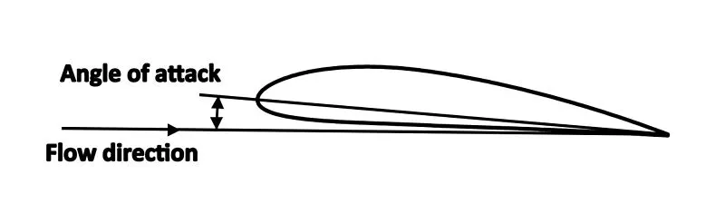
Angle of attack is the angle between a reference line on a body and the vector representing the relative motion between the body and the fluid through which it is moving. In aerodynamics, the angle of attack specifies the angle between the chord line of the wing of a fixed-wing aircraft and the vector representing the relative motion between the aircraft and the atmosphere.
Angle of attack is the angle between the body's reference line and the oncoming flow.
1) FLOW SIMULATION setup
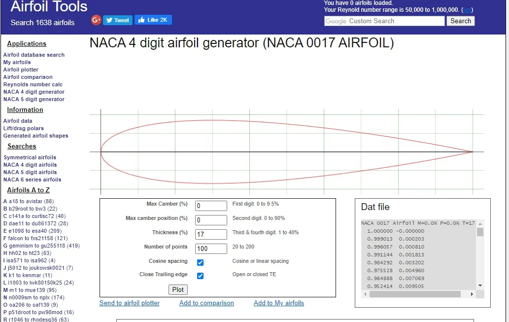
1.Airfoil specification DATA
airfoil NACA-0017
source site (http://airfoiltools.com/airfoil/index)
by using 4 digit NACA airfoil generator
This NACA airfoil series is controlled by 4 digits e.g. NACA 0017, which designate the camber, position of the maximum camber, and thickness. If an airfoil number is
e.g.
NACA 0017
- M is the maximum camber divided by 100. In the example M=0 so the camber is 0.0 or 0% of the chord
- P is the position of the maximum camber divided by 10. In the example P=0 so the maximum camber is at 0 or 0% of the chord.
- XX is the thickness divided by 100. In the example XX=17 so the thickness is 0.17 or 17% of the chord.
converting 2axis Dat file to 3-axis Dat file
copy NACA-0017 airfoil Dat file (2-axis) to the notepad
by adding third axis data in text data file (adding zero as z-axis to every point)
the 3-axis Dat file saved as NACA0017
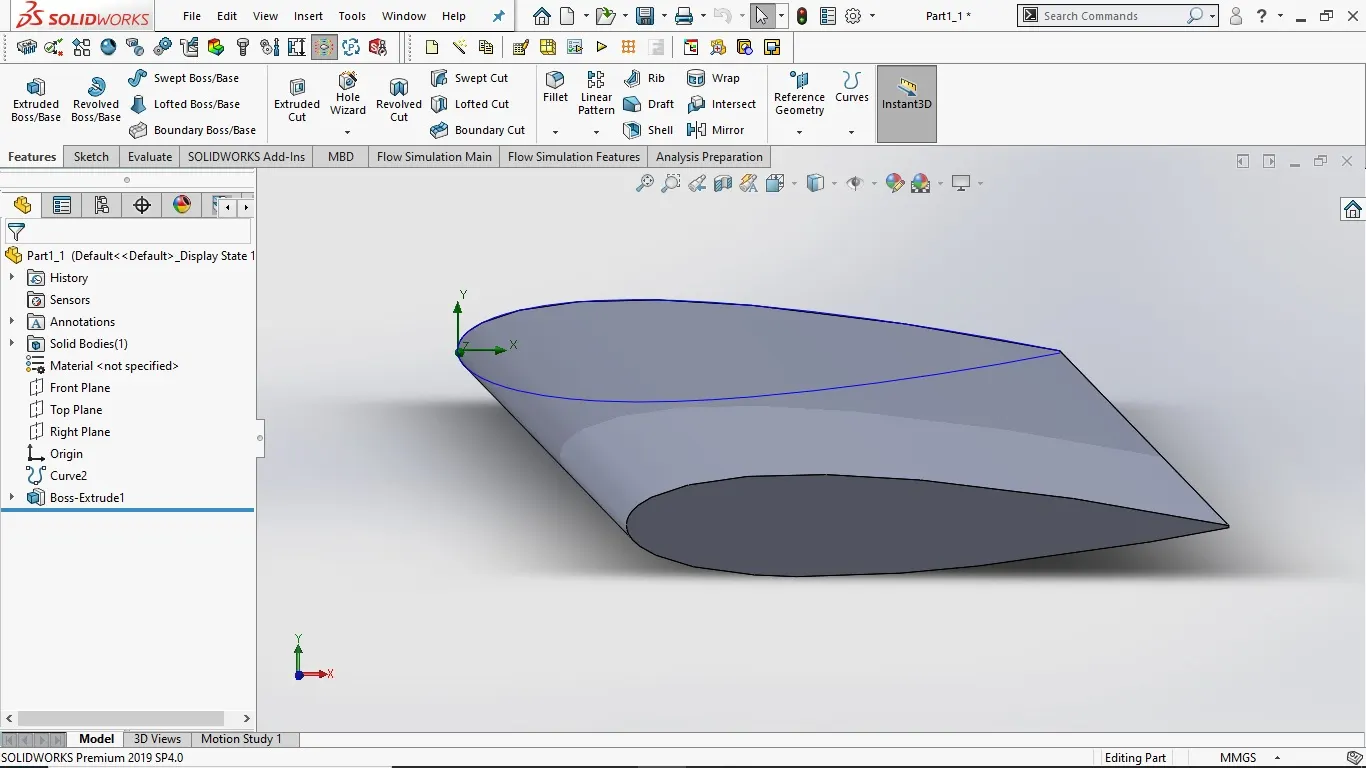
2. airfoil NACA0017 model
- by adding curve through XYZ point via insert curve
- extrude model up to 5mm
- rotate the model at origin for change in the angle of attack (0,2,4,6,8,10)
3.flow simulation wizard setup
case 1
project name:- airfoil_0deg (changes as angle of attack changes)
analysis type: external flow
time 5sec steps 1sec
fluids: air
velocity parameter
x-axis 600m/s
4.computational domain setup
type 2D simulation
domain size
X-min: -5mm , X-max: 15mm X-size :20mm
Y-min : -10mm Y-max : 10mm Y-size :20mm
5. adding Goals (result parameter)
1 global goal X-axis force
2 global goal y-axis force
3. global goal X-axis friction force
4. global goal Y-axis friction force
5.(airfoil)surface goal X-axis force
6. (airfoil)surface goal Y-axis force
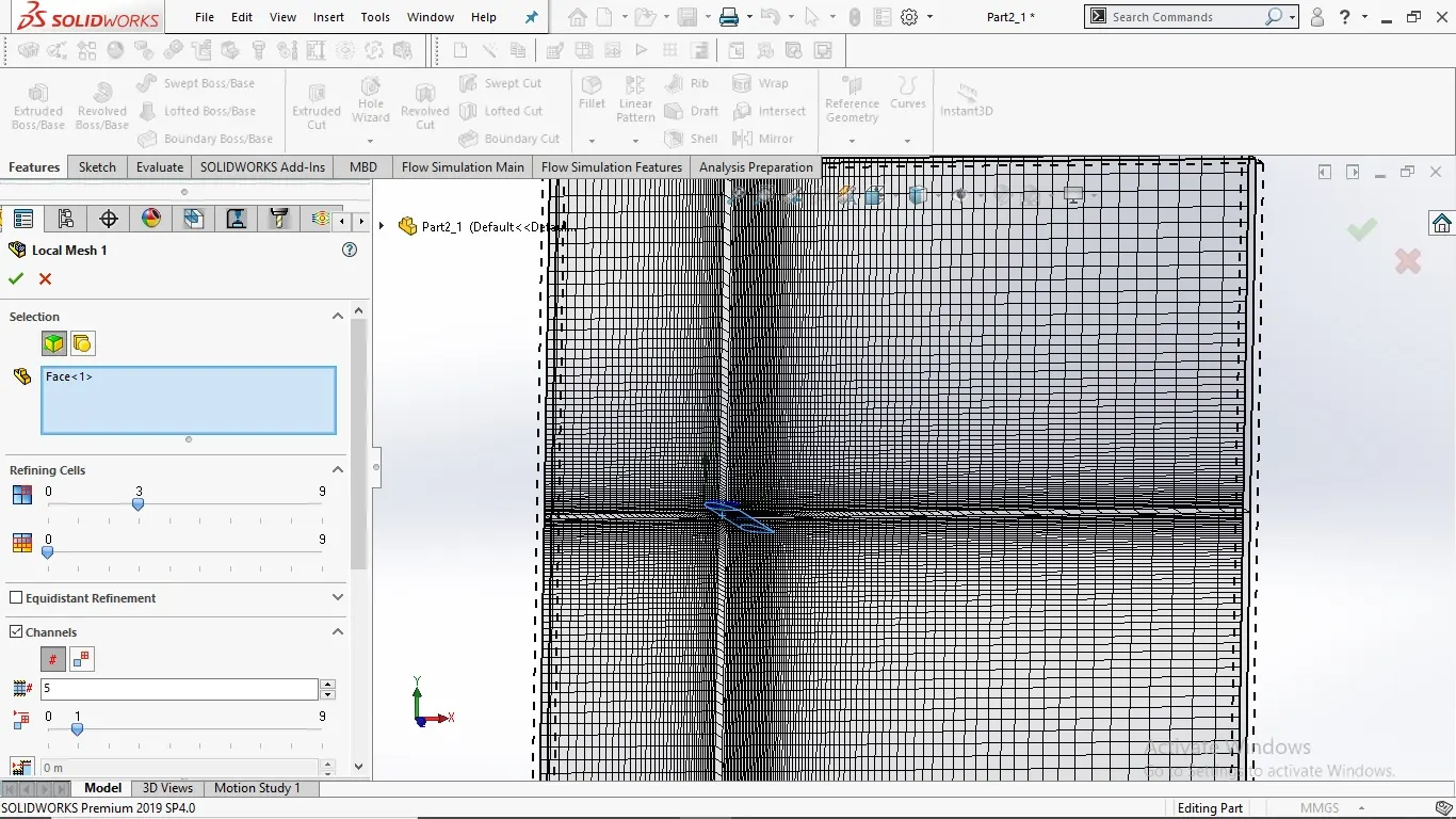
6. mesh setting
global mesh level 3
advance channel refinement
inserting local mesh
area: airfoil surface
refining cells level 3
7. insert cut plot
pressure plot
velocity plot
8.run the flow simulation wizard
case 1
angle of attack 0
results
pressure cut plot contour
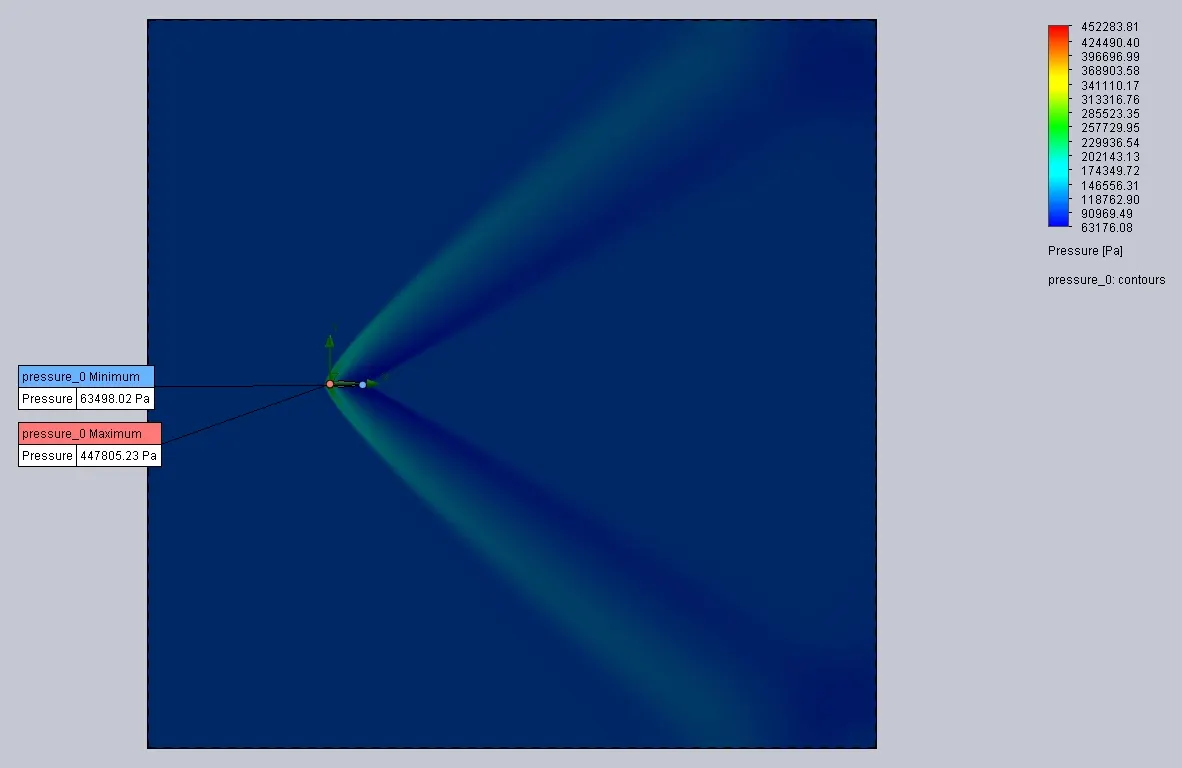
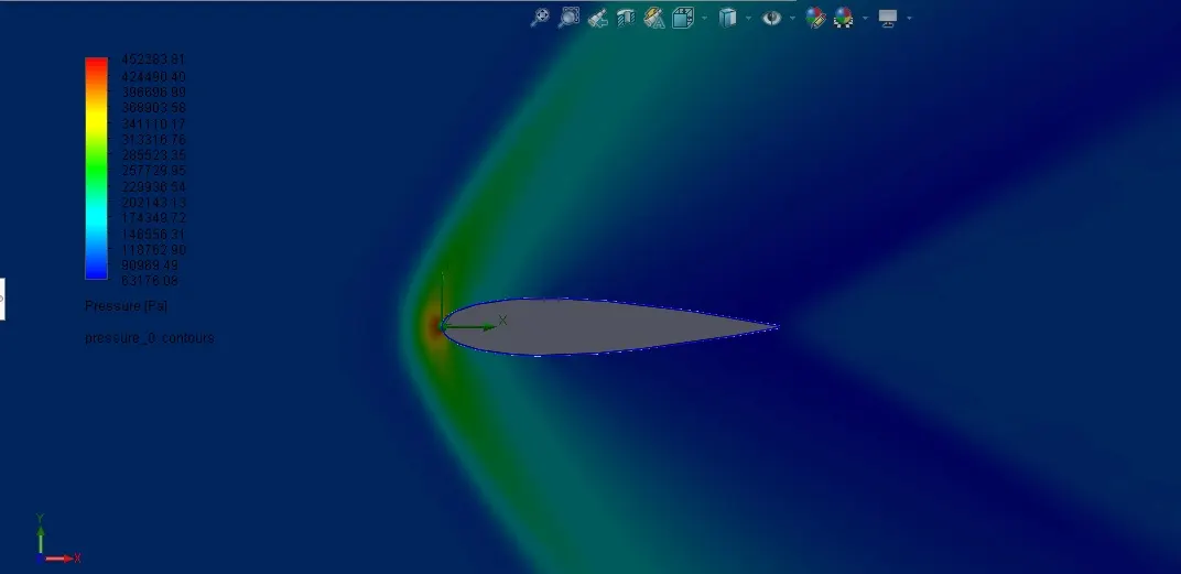
velocity profile cup lot contour
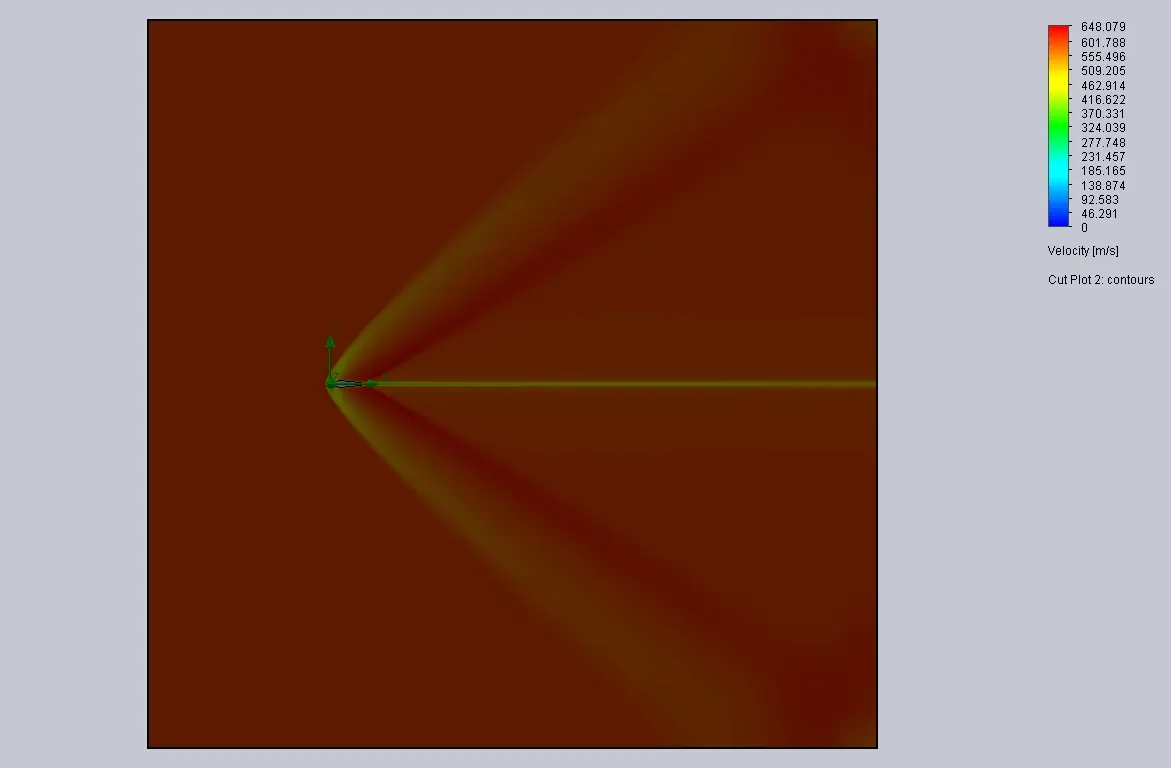
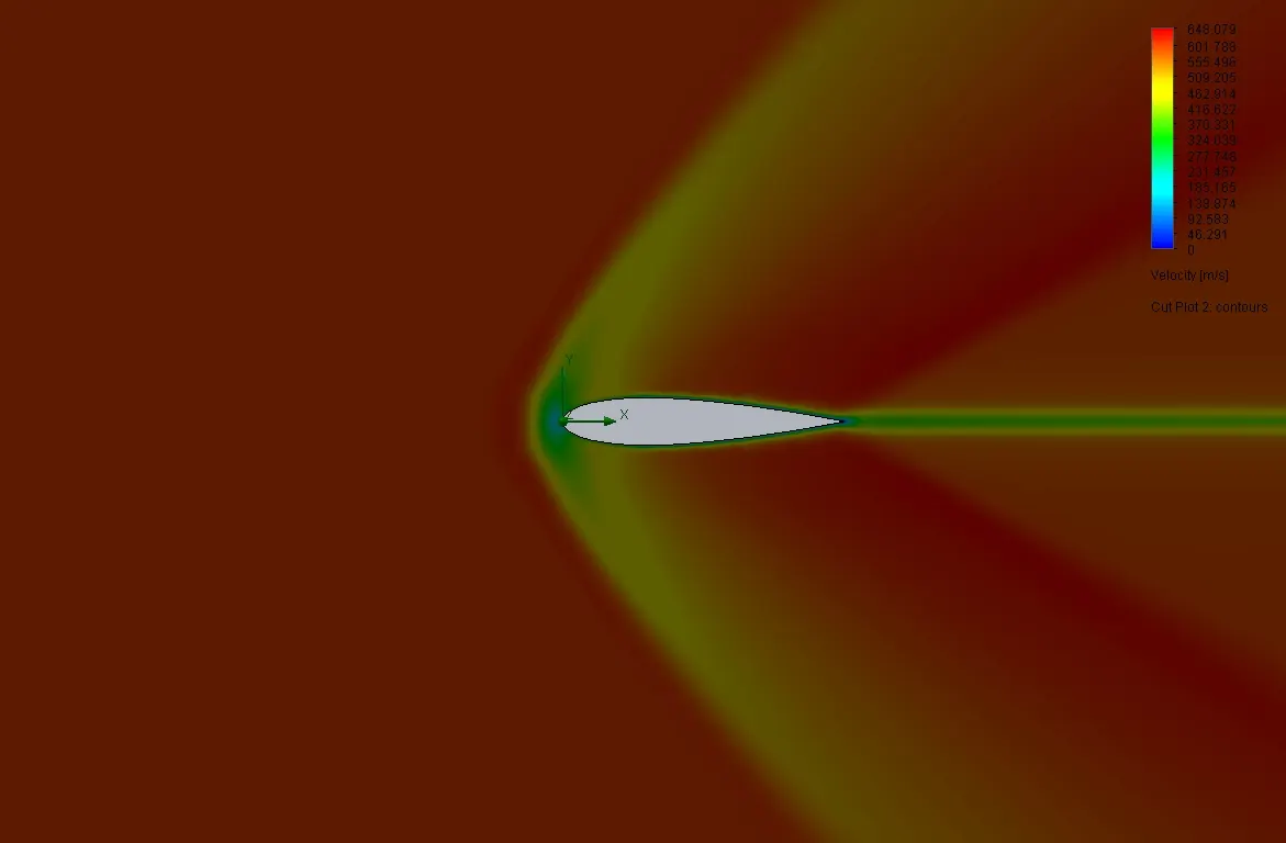
goal plot results
| Goal Name | Unit | Value | Averaged Value | Minimum Value | Maximum Value |
| GG Force (X) 1 | [N] | 0.039244682 | 0.039240244 | 0.039052627 | 0.03942204 |
| GG Force (Y) 1 | [N] | -1.14634E-05 | -4.32927E-05 | -0.000280277 | 0.000147754 |
| GG Friction Force (X) 1 | [N] | 0.004765598 | 0.004762518 | 0.004755948 | 0.004769911 |
| GG Friction Force (Y) 1 | [N] | -1.58329E-06 | -3.3923E-07 | -4.48093E-06 | 2.53877E-06 |
| SG Force (X) 1 | [N] | 0.039138141 | 0.039133732 | 0.038946061 | 0.039315455 |
| SG Force (Y) 1 | [N] | -1.1477E-05 | -4.33475E-05 | -0.000280333 | 0.000147644 |
case2
angle of attack 2 deg
rotating the model by-2 deg to origin in the x-axis
pressure cut plot contour
velocity cut plot contour
goals results
| Goal Name | Unit | Value | Averaged Value | Minimum Value | Maximum Value |
| GG Force (X) 1 | [N] | 0.039370956 | 0.039448363 | 0.03929297 | 0.039682477 |
| GG Force (Y) 1 | [N] | 0.016069445 | 0.015961761 | 0.015615986 | 0.016262278 |
| GG Friction Force (X) 1 | [N] | 0.0045565 | 0.004565306 | 0.004553428 | 0.004580192 |
| GG Friction Force (Y) 1 | [N] | -0.00011329 | -0.000115993 | -0.000119191 | -0.000113294 |
| SG Force (X) 1 | [N] | 0.039275004 | 0.03935151 | 0.039198308 | 0.039586676 |
| SG Force (Y) 1 | [N] | 0.016074137 | 0.015965764 | 0.015620665 | 0.01626669 |
case3
angle of attack 4deg
pressure cut plot contour
velocity cut plot contour
goal results
| Goal Name | Unit | Value | Averaged Value | Minimum Value | Maximum Value |
| GG Force (X) 1 | [N] | 0.041096957 | 0.041118777 | 0.040915254 | 0.041386592 |
| GG Force (Y) 1 | [N] | 0.031302866 | 0.031456527 | 0.030992213 | 0.032026993 |
| GG Friction Force (X) 1 | [N] | 0.004661803 | 0.004662557 | 0.004654716 | 0.004672471 |
| GG Friction Force (Y) 1 | [N] | -0.0002475 | -0.000247383 | -0.000248989 | -0.00024436 |
| SG Force (X) 1 | [N] | 0.040983504 | 0.041005682 | 0.040801997 | 0.041273228 |
| SG Force (Y) 1 | [N] | 0.031308335 | 0.031461978 | 0.030997683 | 0.03203243 |
case 4
angle of attack 6deg
pressure cut plot contour
velocity cut plot contour
goal results
| Goal Name | Unit | Value | Averaged Value | Minimum Value | Maximum Value |
| GG Force (X) 1 | [N] | 0.043358533 | 0.043556888 | 0.043325051 | 0.043761006 |
| GG Force (Y) 1 | [N] | 0.048420508 | 0.048299414 | 0.048047724 | 0.048466571 |
| GG Friction Force (X) 1 | [N] | 0.004586929 | 0.00459867 | 0.004586929 | 0.004607111 |
| GG Friction Force (Y) 1 | [N] | -0.0003614 | -0.000363152 | -0.000366232 | -0.000361013 |
| SG Force (X) 1 | [N] | 0.043358533 | 0.043556888 | 0.043325051 | 0.043761006 |
| SG Force (Y) 1 | [N] | 0.048420508 | 0.048299414 | 0.048047724 | 0.048466571 |
case5
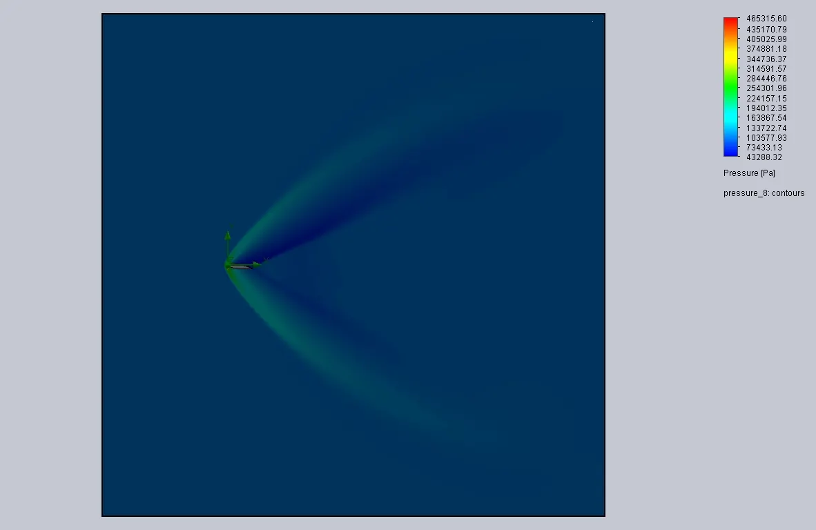
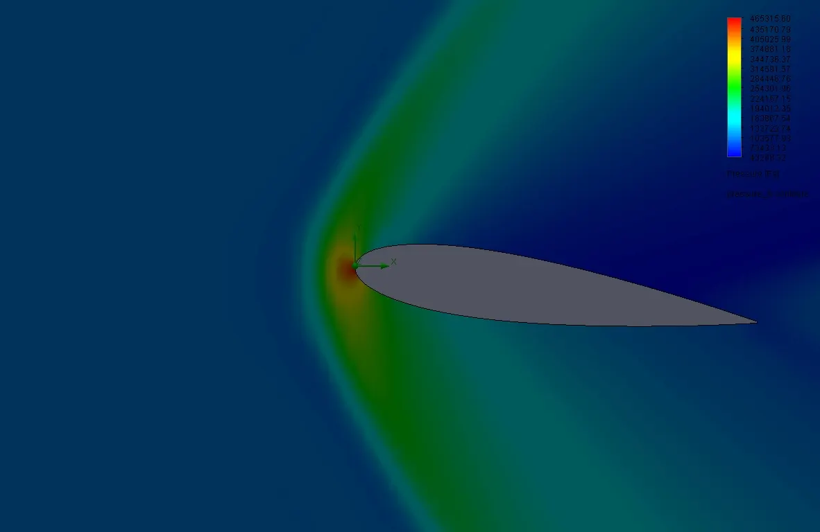
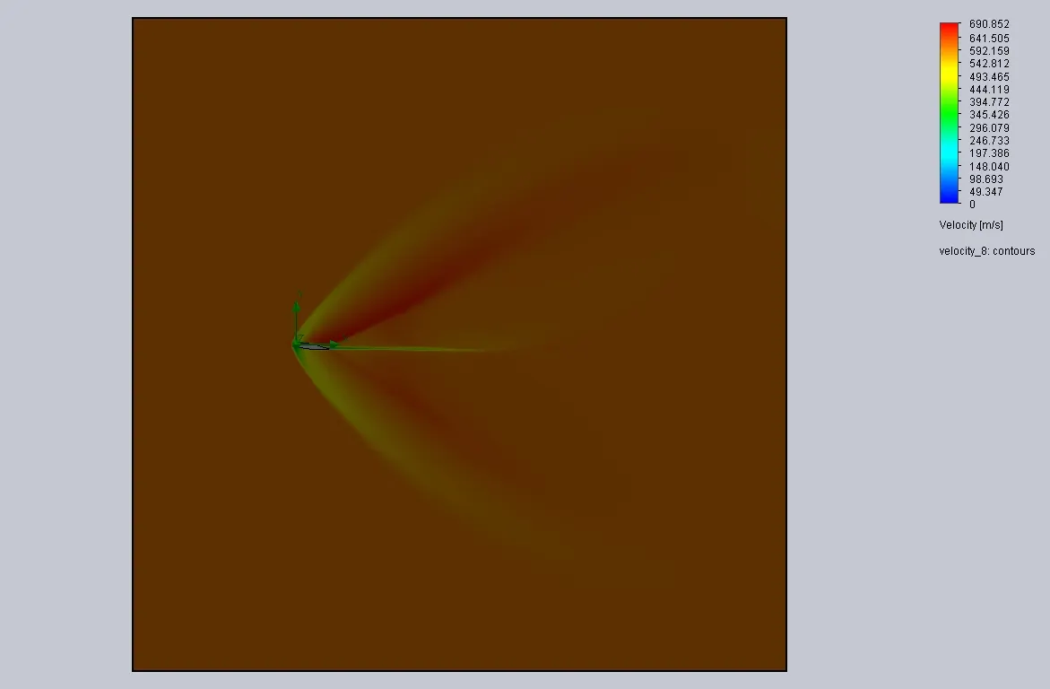
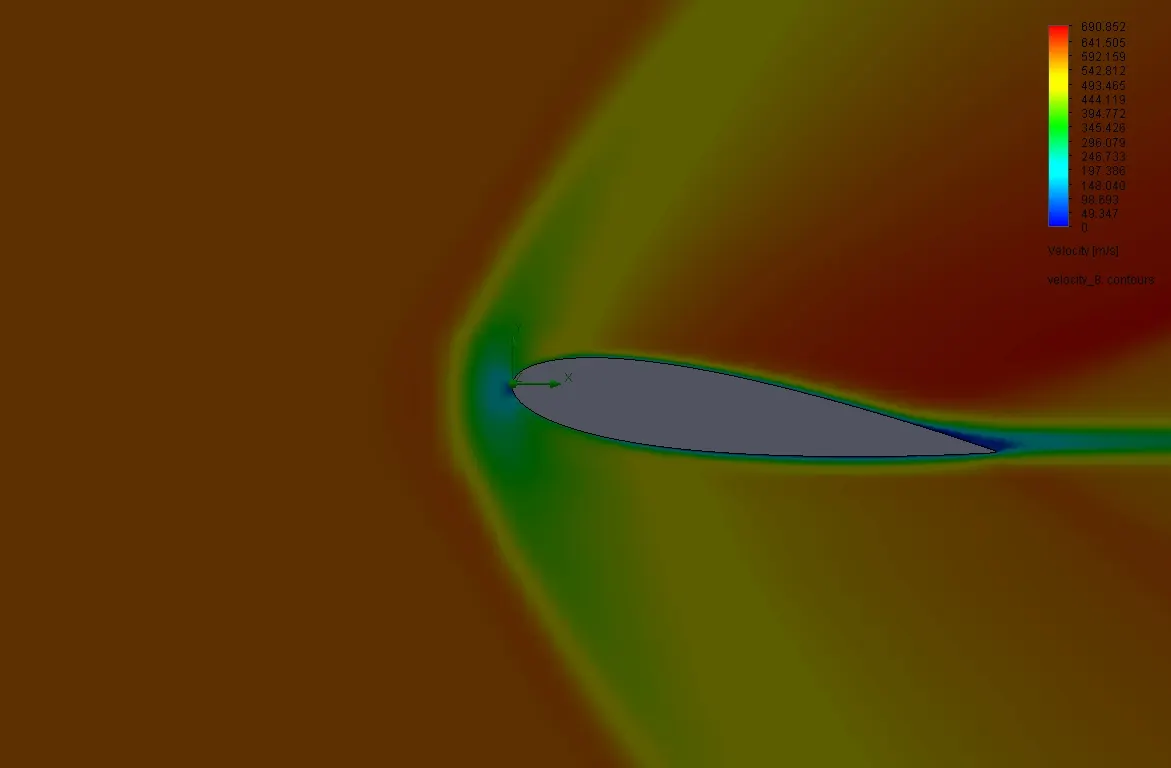
angle of attack 8deg
pressure cut plot contour
velocity cut plot contour
goal results
| Goal Name | Unit | Value | Averaged Value | Minimum Value | Maximum Value |
| GG Force (X) 1 | [N] | 0.046658366 | 0.046616839 | 0.046442535 | 0.046790499 |
| GG Force (Y) 1 | [N] | 0.062570029 | 0.06253162 | 0.062180437 | 0.062911183 |
| GG Friction Force (X) 1 | [N] | 0.004215343 | 0.004224245 | 0.004210822 | 0.004244638 |
| GG Friction Force (Y) 1 | [N] | -0.00041182 | -0.000412851 | -0.000421056 | -0.000402449 |
| SG Force (X) 1 | [N] | 0.046546208 | 0.046503932 | 0.046329741 | 0.046676576 |
| SG Force (Y) 1 | [N] | 0.062584593 | 0.062546296 | 0.062195074 | 0.062925838 |
case 6
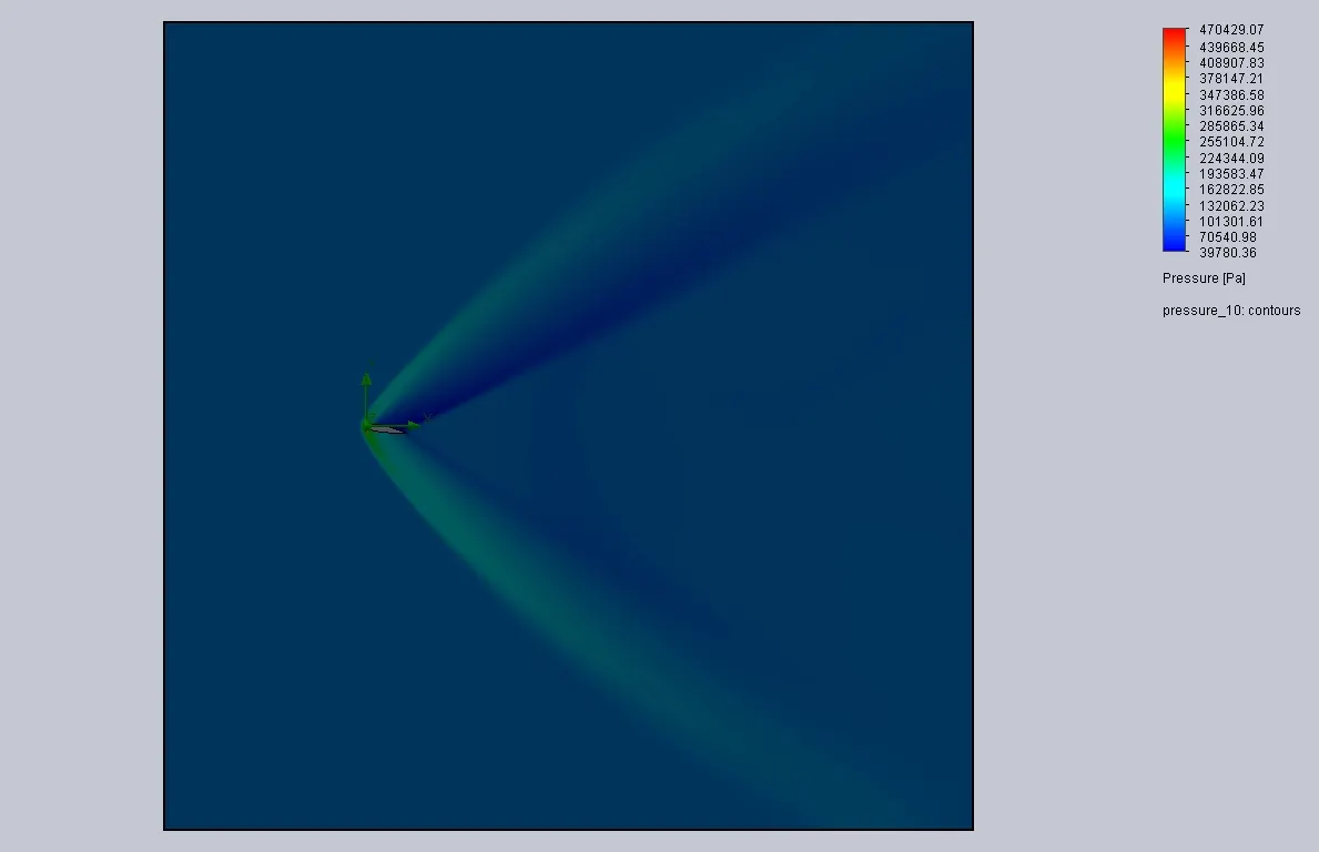
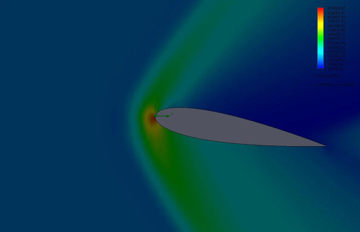
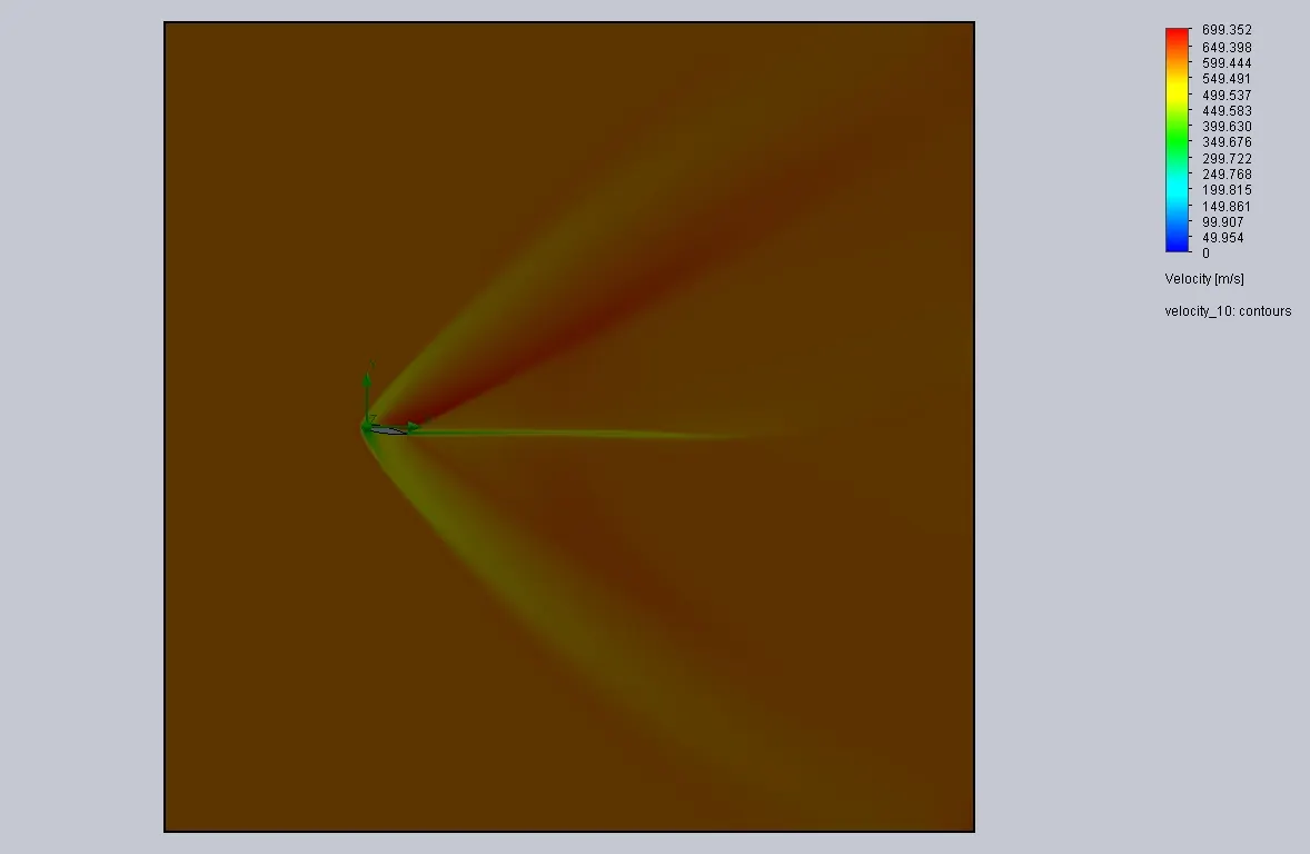
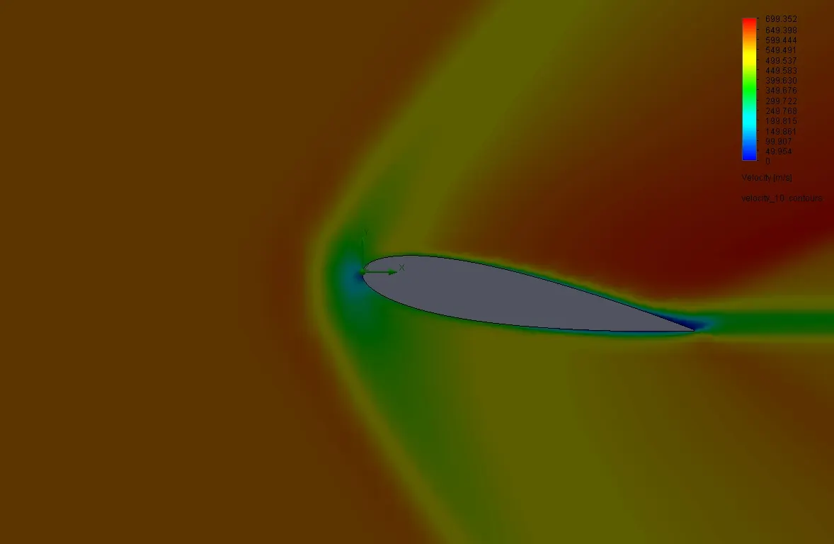
angle of attack 10deg
pressure plot contour
velocity cut plot contour
goal results
| Goal Name | Unit | Value | Averaged Value | Minimum Value | Maximum Value |
| GG Force (X) 1 | [N] | 0.051647984 | 0.051408914 | 0.051139284 | 0.051817388 |
| GG Force (Y) 1 | [N] | 0.079765994 | 0.079839779 | 0.079551515 | 0.080288153 |
| GG Friction Force (X) 1 | [N] | 0.004516018 | 0.004505787 | 0.004491909 | 0.004516018 |
| GG Friction Force (Y) 1 | [N] | -0.00059196 | -0.0005895 | -0.000593323 | -0.000584257 |
| SG Force (X) 1 | [N] | 0.051516821 | 0.051277367 | 0.051007227 | 0.051685779 |
| SG Force (Y) 1 | [N] | 0.079785484 | 0.079859127 | 0.079571254 | 0.080307172 |
5)flow simulation result
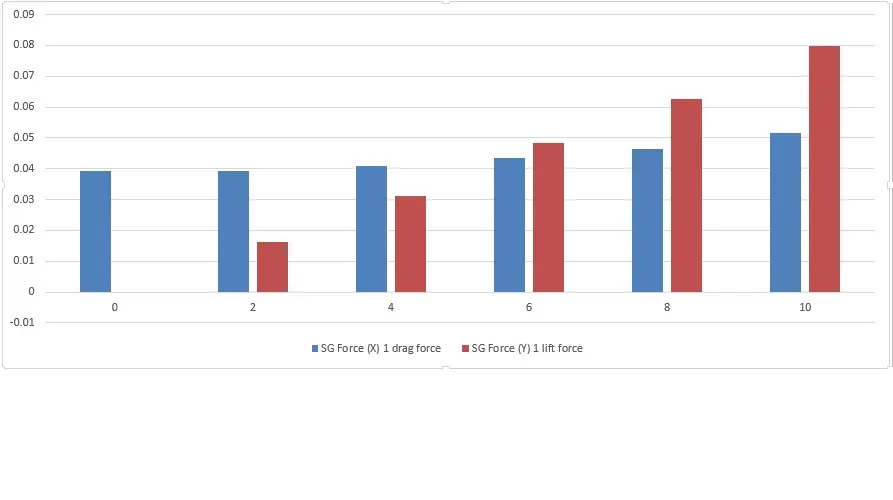
| angle of attack (deg) | SG Force (X) 1 drag force | SG Force (Y) 1 lift force |
| 0 | 0.039138141 | -1.1477E-05 |
| 2 | 0.039275004 | 0.016074137 |
| 4 | 0.040983504 | 0.031308335 |
| 6 | 0.043358533 | 0.048420508 |
| 8 | 0.046546208 | 0.062584593 |
| 10 | 0.051516821 | 0.079785484 |
observation
by comparing all the results from case 1 to case 6 results and goals as follows
1.lift & drag force
- as the angle of attack increases the lift force increases over drag force
- lift force overcomes the drag force from angle of attack 6 deg before it the drag force is higher than the lift force to overcome.
2. pressure
- from angle of attack 0deg to angle of attack 10 deg the pressure building up under the airfoil.
- the pressure force is more than the pressure above the airfoil; it affects to push upward the airfoil.
- as per the relation between the pressure and velocity higher the pressure lower the velocity.
- low pressure above the airfoil feels free to lift upward.
3. velocity.
- from angle of attack 0deg to angle of attack 10 deg the flow of air rises above airfoil.
- the velocity of air is low below the airfoil and high velocity at above the airfoil
- as per the relation between the pressure and velocity higher the pressure lower the velocity.
- high velocity above the airfoil give more dragging.
- as the velocity rises the drag force on the airfoil rises.
conclusion
as angle of attack changes airflow direction changes by the boundary layer separation pressure and velocity values changes and tends to changes in lift and drag force.