Flow over a backward facing step
OBJECTIVE:
To perform a 2-D bacward facing step simulation using CONVERGE CFD by applying three different mesh sizes and comparing the results of resulting three simulations.
The different mesh sizes are:
- dx =2e-3m, dy = 2e-3m, dz = 2e-3m
- dx =1.5e-3m,dy = 1.5e-3m, dz = 1.5e-3m
- dx =1.0e-3m,dy = 1.0e-3m, dz = 1.0e-3m
INTRODUCTION:
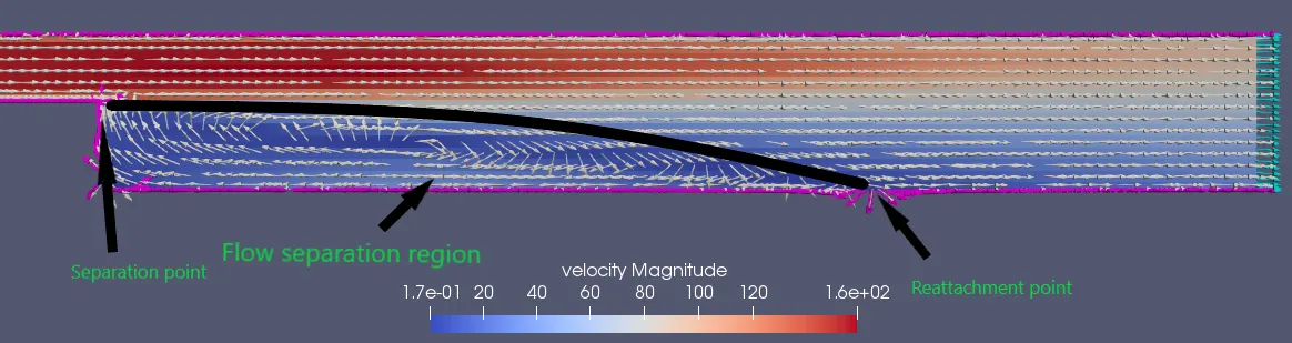
Backward facing step is performed inorder to find the separated flow region by identifying its separation point and reattachment point.
Flow separation is regrettable in most cases and should be avoided to the maximum extent since it affects the flow rate in both internal and external flows.
Identifiying the regions of flow separation is important in many applications for different reasons. Some reasons to reduce flow separation across different fields are:
- Aerodynamics- it increases drag and reduces the lift of the object
- Automobiles- it decreases the efficiency of the vehicles by resisting its flow
- High Rise Buildings- it affects the stability as the buildings tend to sway at greater heights due to high wind force
- Ducts- results in uneven air distribution and reduces the efficiency by decreasing the flow rate
CFD Analysis:
Geometry:
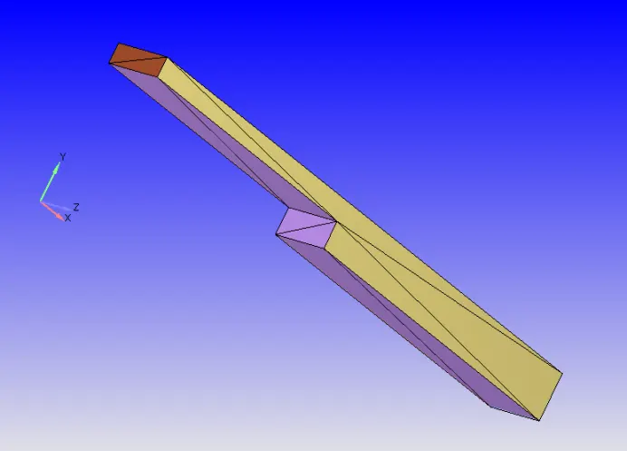
Pre-processing:
Application:- Converge Studio
Case Setup:
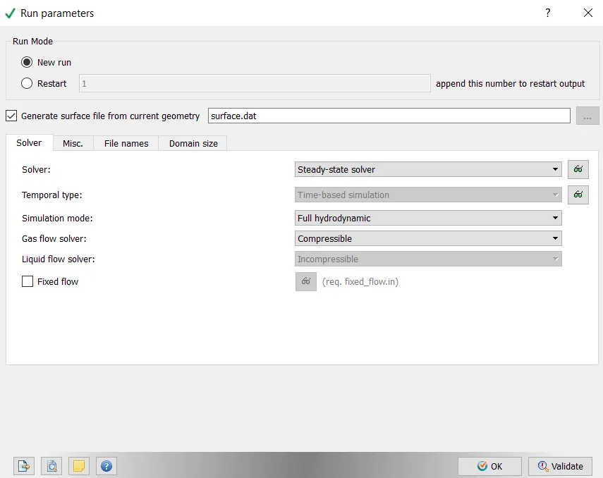
- Run Parameters- we are using a steady state solver for the compressible fluid.
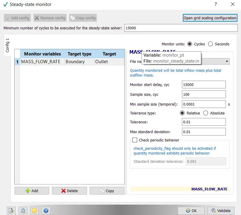
- We are running the simulation for 15000 cycles with sample size every 1oo cycles so that we get 150 sets to compare the results at different situations.
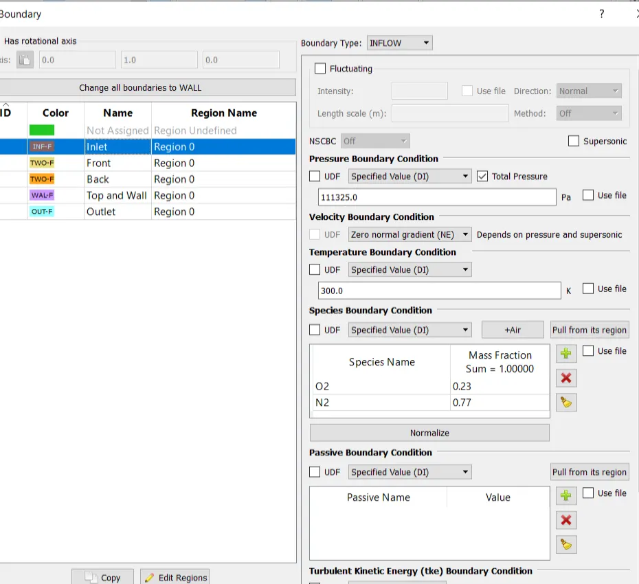
- The boundaries are flagged accordingly and then grouped into a single region.
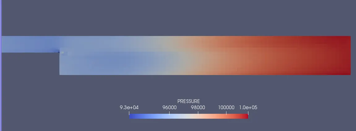
- Inlet Pressure= 111325 pa; Region Pressure= 110325 pa; Outlet Pressure= 101325 pa (Ip>Rp>Op)
- For Turbulence modeling, RNG k-epsilon is used.
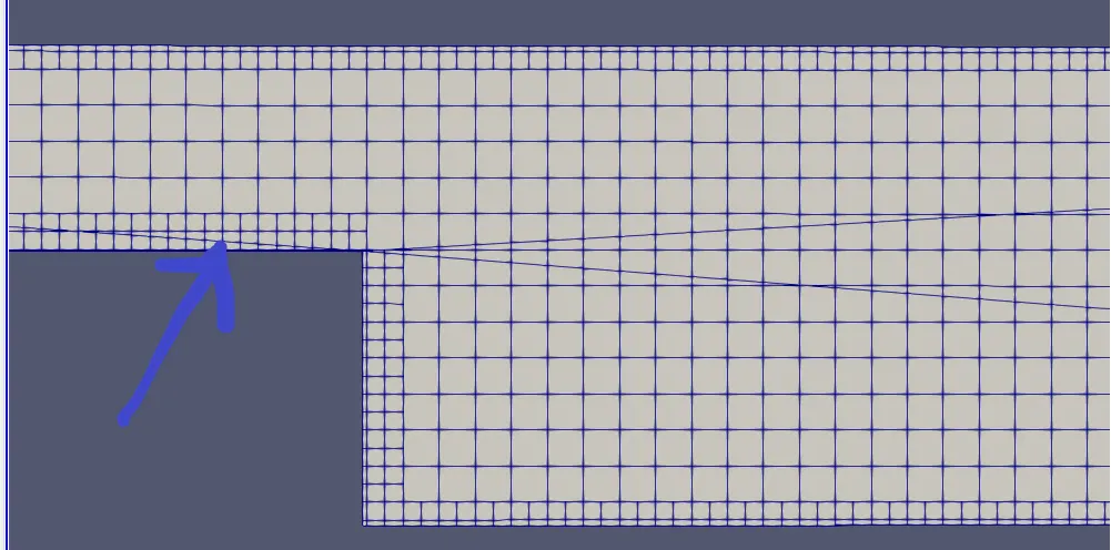
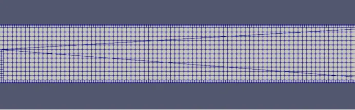
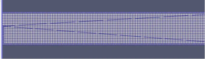
- Along with different mesh sizes for each case, fixed embedding is employed along the boundaries to get more accurate results in these regions as flow separation and reattachment takes place here.
Simulation:
Command Application: CYGWIN
Post-processing:
RESULTS:
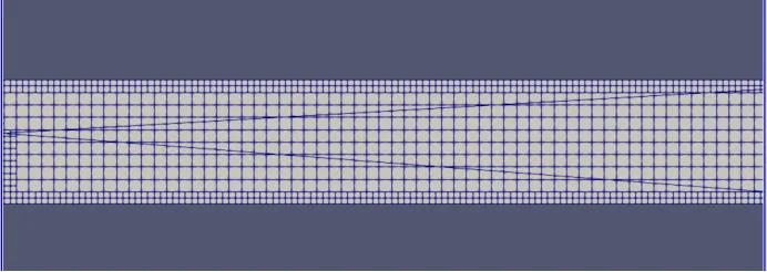
Mesh for each cases are zoomed to the same extent.
Case1: (dx =2e-3m, dy = 2e-3m, dz = 2e-3m)
Mesh Size:
Pressure Contour:
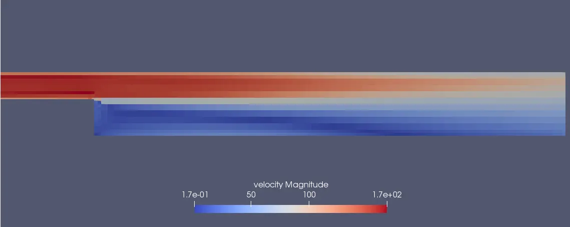
Velocity Contour:
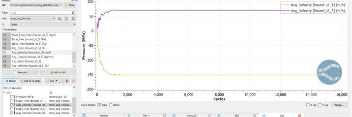
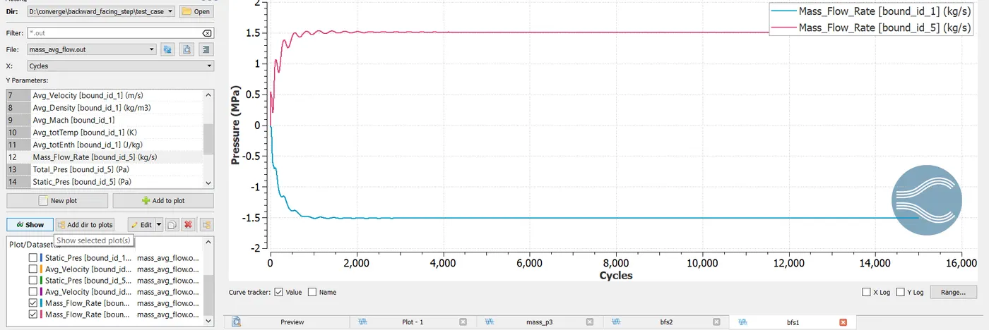
Mass Flow Rate:
Case2: (dx =1.5e-3m, dy = 1.5e-3m, dz = 1.5e-3m)
Mesh Size:
Pressure Contour:

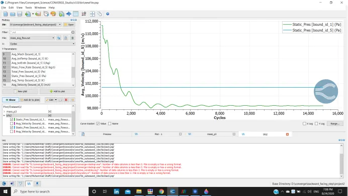
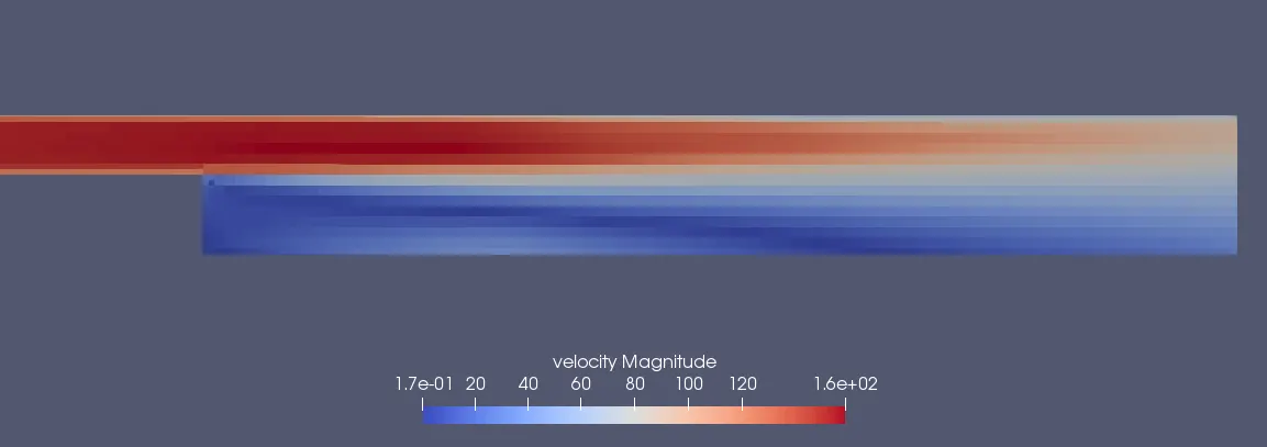
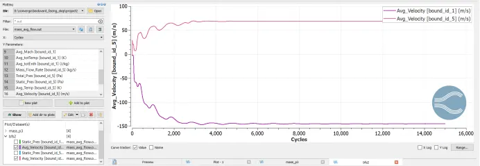
Velocity Contour:
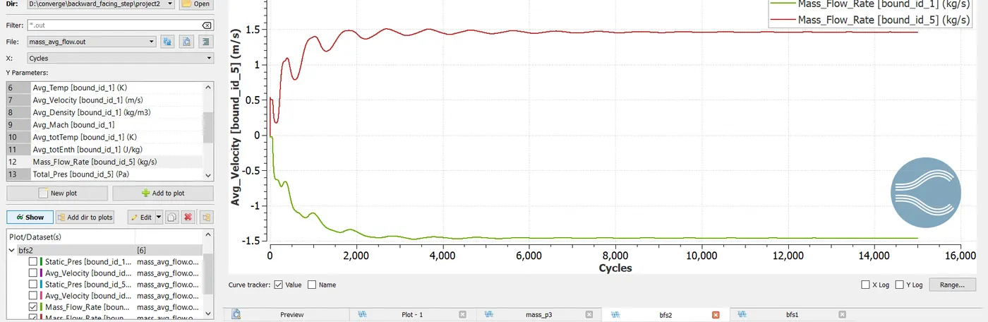
Mass Flow Rate:
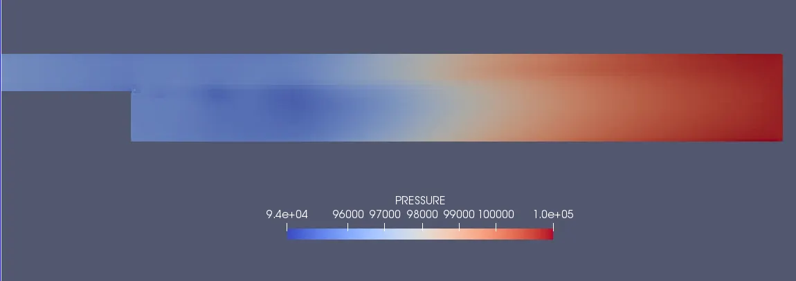
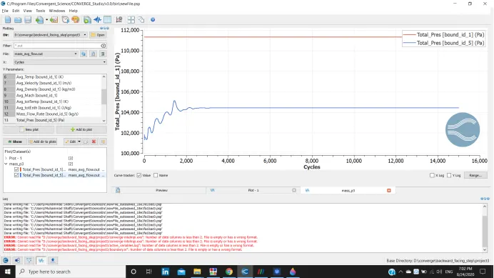
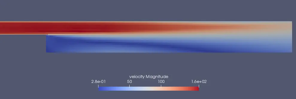
Case3: (dx =1e-3m, dy = 1e-3m, dz = 1e-3m)
Mesh Size:
Pressure Contour:
Velocity Contour:
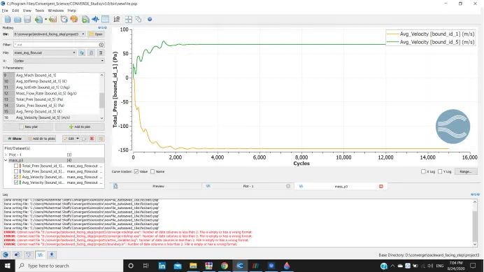
Mass Flow Rate:
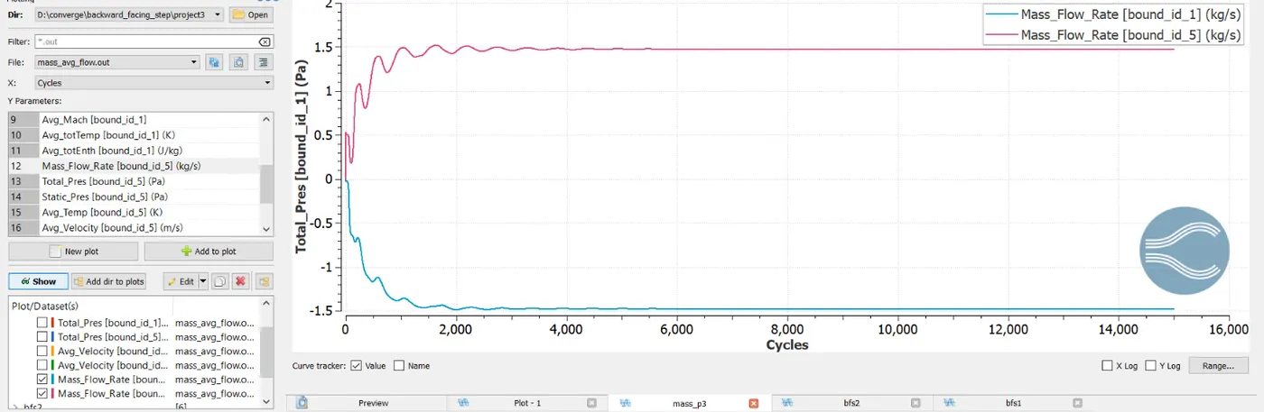
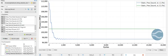
- In each of the above cases the Inlet mass flow is almost equal to the Outlet mass flow rate adhering to the the principle of conservation of mass.
- It can be observed that the flow has reached steady state within a short period implying that 15000 run cycles is quite too much for this simulation.
COMPUTATIONAL TIME:
|
Case |
Mesh Size |
Time Taken |
|
1 |
dx =2e-3m, dy = 2e-3m, dz = 2e-3m |
175.658764 seconds |
|
2 |
dx=1.5e-3m ,dy=1.5e-3m, dz=1.5e-3m |
331.676207 seconds |
|
3 |
dx=1e-3m, dy=1e-3m, dz=1e-3m |
440.195905 seconds |
TOTAL CELL SIZE:
|
Case |
Mesh Size |
Cell Count |
|
1 |
dx =2e-3m, dy = 2e-3m, dz = 2e-3m |
1943 |
|
2 |
dx=1.5e-3m ,dy=1.5e-3m, dz=1.5e-3m |
2994 |
|
3 |
dx=1e-3m, dy=1e-3m, dz=1e-3m |
5516 |
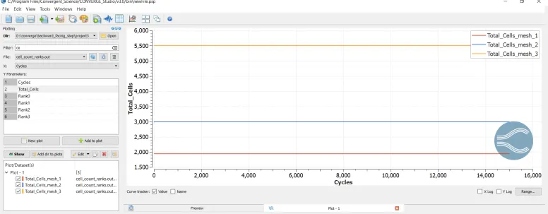
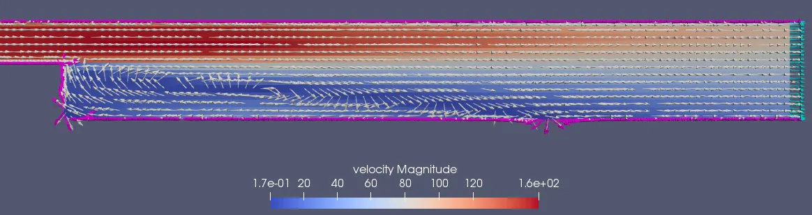
Velocity Vector Contour:
It can be observed that due to sudden increase in volume(sharp turning) the high velocity fluid detaches from the surface of the body resulting in flow separation.
CONCLUSION:
- As the mesh size becomes denser, the time taken to complete the simulation increases drastically.
- As the mesh size increases, the total number of cell also increases.
- Gradual curve instead of sharp bends can prevent flow separaion.
- It can observed from the velocity vector contour that due to sudden increase in volume:
- flow velocity reduces significantly
- flow velocity becomes uneven across the region
- flow separation occurs at the bottom resulting in re-circulation
YOUTUBE LINK:
Mesh 1:- https://youtu.be/Lg5tFVtI9gU
Mesh 2:- https://youtu.be/kHndnF203Yw
Mesh 3:- https://youtu.be/UJB95zezQ1Y