Flow around an Ahmed Body
Objective
- Perform a numerical analysis of flow around an Ahmed body using the Fluent package for 3 different configurations of slant surface inclinations `25^o`, `30^o`, and `35^o`.
- Observe the characteristic flow patterns in each configuration.
- Determine the variation of coefficient of drag with variation in slant angle.
Introduction
The Ahmed body is a bluff body resembling a generic car(a simplified vehicle body) that was first introduced by S.R. Ahmed in 1984 in an article named "Some salient features of the time-averaged ground vehicle wake". Since then the Ahmed body has become a benchmark for analyzing the flow characteristics around any vehicle, more specifically cars although it has a simple shape. The key variable dimension of this bluff body is the inclination of the slant surface with the horizontal with its length remaining constant. From the measurements obtained in the wind tunnel test conducted by S.R. Ahmed, it was observed that three horseshoe vortices are formed in the wake of the flow.
- One vortex is formed by the flow separation at the verticle back face of the model.
- The second one is formed by the flow separation from the base of the model.
- The third one is formed by the flow separation at the side boundary of the slant surface. This vortex is called a C-pillar vortex.
The vortices are formed due to the low-pressure region created in the wake of the Ahmed body. And hence the pressure difference between the front and the wake contributes to the drag force on the bluff body, this portion of the drag is called pressure drag. From the experimental observations, it has been noticed that the inclination of the slant surface determines the pressure drag and the vortex formation.
For slant angles less than `12^o`, the flow remains attached over the slant surface, it can be considered as a 2-D flow with low drag. As the slant angle increases from `12^o` to `30^o`, the pressure drag increases considerably and reaches its peak at `30^o`. The drag decreases after `30^o` as the flow separates fully off the slant, it also causes weaker c-pillar vortices.
Below is the CAD model of Ahmed body.
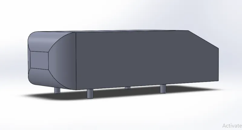
Considered Test Case
The experimental analysis was originally carried out by S.R. Ahmed in 1984 in which the free stream velocity considered was 60m/s and a Reynolds number of 4.29 million based on the model length. Experiments with two configurations of `25^o` and `35^o` slant angle have been conducted by Lienhart and Becker with detailed LDA and HWA measurements in the LSTM low-speed wind tunnel with a free stream velocity of 40m/s. The Reynolds number considered is 2.784 million based on the model length.
The current project is based on the data provided by Lienhart and Becker with the inclusion of an additional `30^o` slant angle.
Geometry Modeling
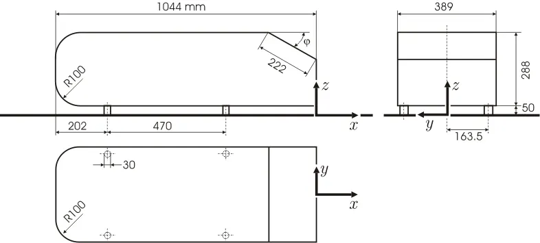
A CAD model of the Ahmed body has been designed in SpaceClaim with the below-shown dimensions. But the legs of the body have not been considered in the 3-D model.
A virtual wind tunnel has been set up around Ahmed body for the flow analysis whose dimensions are given below.
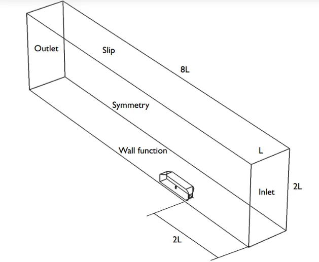
The length of Ahmed body is considered as `l`. The flow in the wind tunnel is considered to turbulent, hence a sufficient flow length is required to achieve a developed turbulent flow. The flow inlet is placed at a distance of `2l` from the front surface of the geometry and the control volume extends up to a distance of `5l` behind the rear surface of the geometry and the height is `2l`. The larger distance behind the geometry is to capture the wake region accurately.
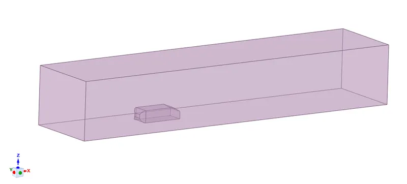
Once the wind tunnel is built around the body, the volume of the Ahmed body is subtracted from the control volume. This remaining volume defines the region of fluid flow. Since the Ahmed body is symmetric about a central plane along the length of the body, the flow will also be symmetric about the symmetry plane. So, one half of the control volume is removed to reduce the computational cost.
Mesh Generation
The 3-D geometry constructed in SpaceClaim is imported into ICEF CFD. ICEM CFD is a mesh generation which is capable of generating high-quality meshes.
- The existing body part is deleted, and a new body part of the geometry is created using two diagonal points such that the new body part rests within the geometry.
- Now each surface is made a part.
- The surfaces of Ahmed body are divided into 4 parts. One part consisting of the front faces, one part for the slant surface, one part for the rear surface, and one part for the remaining surfaces of the Ahmed body.
- The inlet surface is made an individual part.
- The outlet surface is made an individual part.
- The top, side, road, and the symmetry planes are made individual parts.
- All the curves and all the points are grouped into two separate parts.
Tetrahedral and prism elements are utilized to discretize the control volume. The mesh parameters are set up to generate a mesh grid in the control volume.
Global Mesh setup
Tetrahedral Elements
The global element seed size = 0.02m
Global element scale factor = 8
Curvature/proximity-based refinement
Minimum size limit = 0.000500000025m
Elements in gap = 6
Refinement = 40
The maximum size of the tetrahedral elements will be `0.02xx8=0.16mm`. The curvature/proximity-based refinement is subjected to boundaries having curved surfaces and narrow control volume. In situations such as the region between the base of the Ahmed body and the road, to obtain a clear discretization of the volume, curvature/proximity-based refinement assigns 6 elements across the width with a minimum size limit of 0.000500000025m.
Prism Elements
Number of layers = 3
Growth ratio = 1.2
Growth law = Exponential
Initial height = 0m
Part Mesh Setup
Individual surface parts are assigned a maximum value of mesh size to adequately capture the flow characteristics.
The surfaces covering the Ahmed body is given a maximum element size = 0.002m
The remaining surfaces are given a maximum element size = 0.016m
The prism option is enabled for the Ahmed body surfaces and the road.
Density Box
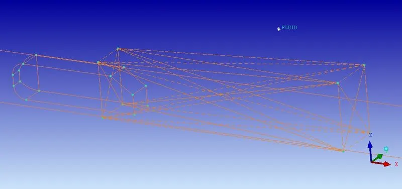
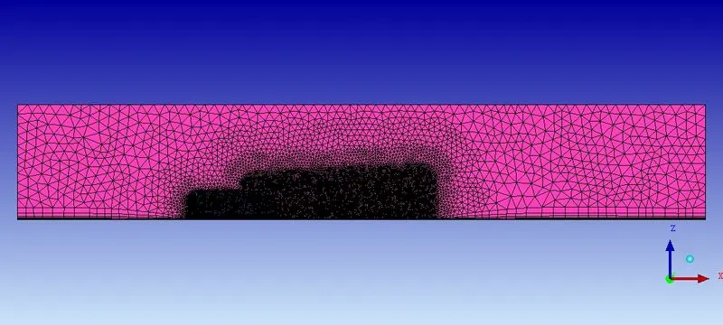
Since the wake region of the Ahmed body becomes a low-pressure region, the turbulent flow in this region is to be analyzed with greater accuracy than the rest of the control volume. To properly acquire the flow separation and the formation of vortices, the mesh density is increased in the wake region of the body. The high mesh density is obtained using a 'Density box'.
The Density box used is in the shape of an elongated hexahedron whose cross-section area increases along its length. The narrower portion starts just before the slant surface covering the slant and rear surfaces, and it extends up to a length of `2l`. The density box widens along the length to capture as many disturbances as possible.
Maximum size of element = 0.003m
Width = 3
Ratio = 1.2
The maximum size of the element in the density box is 0.003m, for every 3 layers the size of the element becomes 1.2 times the previous layers. Below shown is the density box.
Octree Mesh Generation
Once the density box has been placed and all the mesh parameters have been entered, a tetrahedral mesh is generated using the 'Octree' or 'Robust' method. The octree method is chosen because this method of meshing has the ability to provide very good surface meshes. Once the mesh is generated, all the volume mesh elements are deleted only leaving the surface mesh.
Surface Smoothing
Since Octree mesh has developed a good quality surface mesh, now surface smoothing operation is performed so that any cells which have high skewness or be defected may improve the mesh parameters. Laplacian smoothing is also used.
Delaunay Mesh Generation
After multiple cycles of surface smoothing, the surface mesh attains a good quality. Once a high-quality surface mesh is attained, the volume mesh elements are generated using the 'Delaunay' or 'Quick' method. It uses the surface mesh to build volume mesh elements.
Prism Mesh Generation
Since prism mesh has 2 triangular and 3 rectangular surfaces, they have a better ability to adapt to the surface than the tetrahedron mesh elements. Once the volume mesh elements have been generated, prism layers are generated for those surfaces which were earlier specified in the Part Mesh setup. Three layers of equal prism cell thickness are generated.
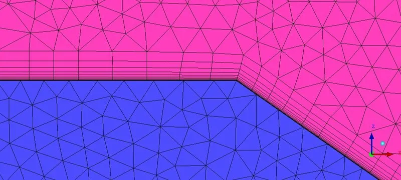
Now the 3 layers are split into 12 layers using the Split mesh function for prism mesh. Each prism cell is divided into 4 parts with a growth ratio of 1.5.
An inflation layer is introduced by varying the thickness of all the 12 prism layers using the Move nodes option on the prism cells with the first cell height of 0.00008m. The height of the last layer is close to the size of the adjoining tetrahedral element.
First Cell Height
Based on the results obtained in the paper "Model Consistent Universal wall functions for RANS turbulence modeling" by T. Knopp, for low values of first cell heights, the surface characteristics obtained from Y+ values ranging from 1 to 50 are almost the same. Hence to remain on the positive side, a Y+ value of 10 has been chosen for this model which yields us the first cell height as 0.00008m.
Final Mesh
Inflation layers
Boundary Conditions
Now ANSYS Fluent solver is setup and Boundary conditions are assigned.
Inlet - Velocity Inlet
Outlet - Pressure outlet
Ahmed body, Road - Wall
Side, Top, Symmetry - Symmetry
Then the mesh file for Fluent is generated.
Pre Processing in Fluent
The mesh file is imported into Fluent, and the necessary preprocessing equation and parameters are assigned.
Operating Condition: Atmospheric pressure = 101325 pa
Flow model: Viscous Realizable `k-epsilon` model with Enhanced wall treatment. It is used to get an accurate analysis of the boundary surface.
Material: Air, Density = 1.225 `kg`/`m^3`, Viscosity = `1.8375xx 10^(-5)``kg`/`ms`
Boundary Conditions
Inlet: Velocity = 40m/s Normal to the boundary, Turbulent Intensity = 0.1%(else default will be 5%).
Outlet: Gauge pressure = 0 Pa.
All parts of Ahmed body, Road: Wall with No-slip condition
Top, Side, Symmetry = Symmetry
Reference Values are obtained from the inlet, Area = 0.056016`m^2`, Length = 1.044m
Solution Methods
Scheme: Coupled
Pressure solver: Second order
Momentum: First Order upwind for first 50 iterations, Second Order upwind for the rest.
Turbulent Kinetic Energy: First Order Upwind
Turbulent Dissipation rate: First Order Upwind
Solution Controls
Flow Courant number: 50
Explicit Relaxation factors: Momentum = 0.4, Pressure = 0.4
The flow courant number is usually 200 and the explicit momentum and pressure relaxation factors are 0.5. But it has been changed as above so that the solution will not blow up. The progress will be slow because of the current values but the Coupled solver will compensate for that.
Under Relaxation factors:
Density = 1,
Body Forces = 1,
Turbulent K.E. = 0.8
Turbulent Dissipation rate = 0.8
Turbulent Viscosity = 0.8 for first 50 iteration, 0.95 for the rest
The momentum solution scheme will be first-order upwind for the first 50 iterations. This is down to accelerate the solution process until a horizontal curve is attained for the drag value. Later the solution scheme is changed to second-order upwind to obtain accurate solutions
Report definitions for the Drag coefficients at the front, slant, rear surface, and the total surface and Lift Coefficient of the Ahmed body are initialized. A report plot and report file for all the drag coefficient values and the same for lift coefficient is initialized.
Hybrid Initialization is used as the initialization method.
Solution calculation is done first for 50 iterations and then for 1000 iterations.
Results
1] Slant inclination = `25^o`
Scaled Residuals
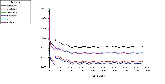
The solution has run up to 850 iterations and seems to have a constant mean value after 300 iterations.
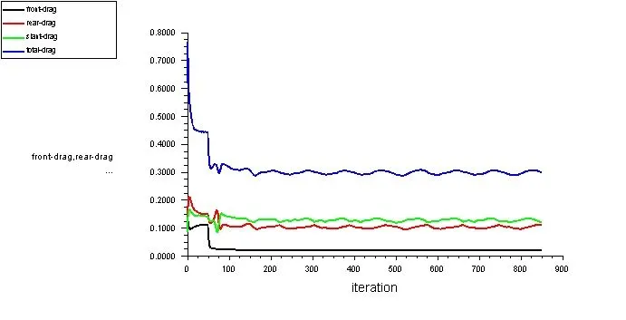
Coefficients of Drag
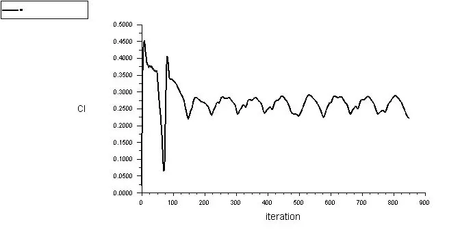
Coefficient of Lift
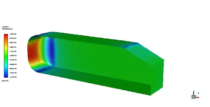
Pressure Contour on Ahmed Body
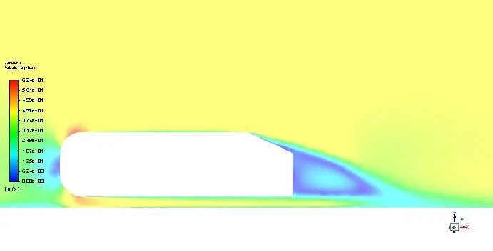
Velocity Contour
Vortices
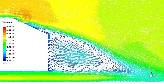
The flow has begun separate along the slant surface and there are 2 vortices in the low-pressure region adjoining the rear surface.
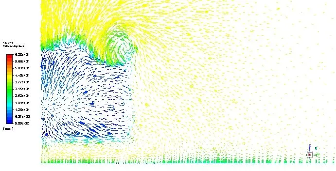
There is a noticeable C-type vortex.
2] Slant inclination = `30^o`
Scaled residuals
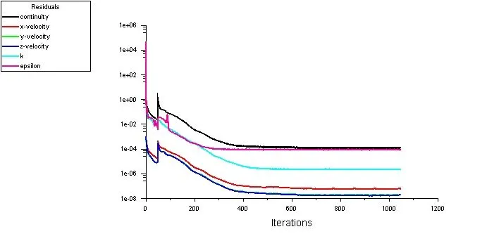
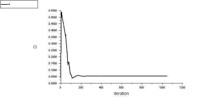
The solution has run up to 1050 iterations and seems to have a constant mean value after 700 iterations.
Coefficients of Drag
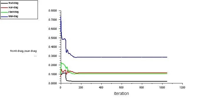
Coefficient of Lift
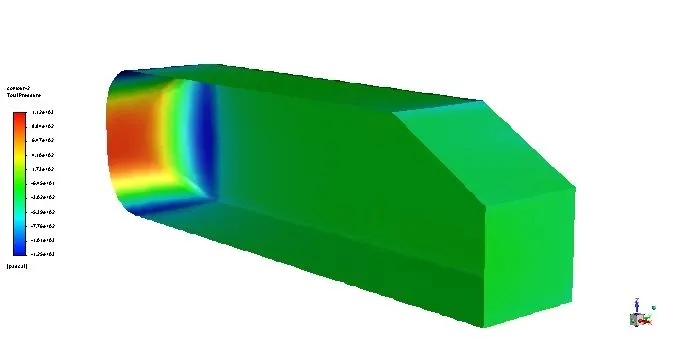
Pressure Contour on Ahmed Body
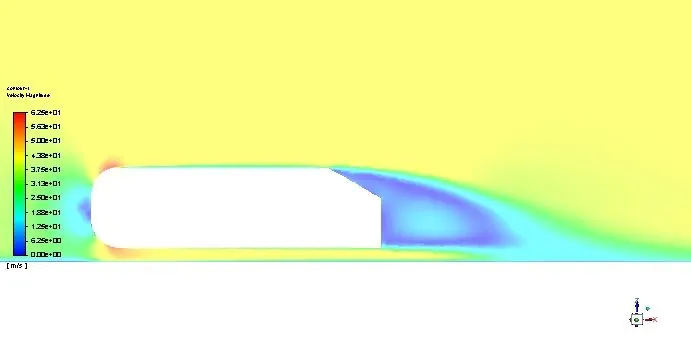
Velocity Contour
Vortices
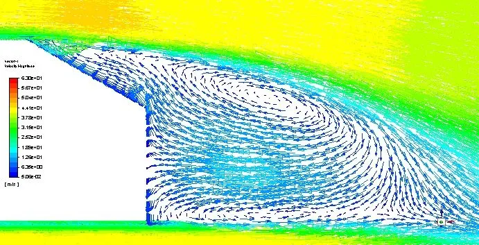
The flow has begun to separate before the slant surface and there are 2 vortices in the low-pressure region adjoining the rear surface and the slant surface.
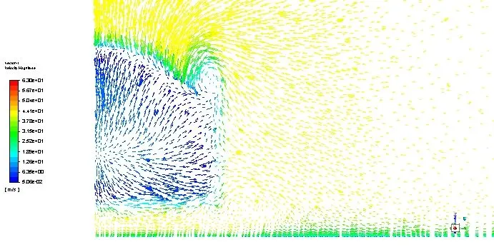
There is a noticeable C-type vortex.
3] Slant inclination = `35^o`
Scaled Residuals
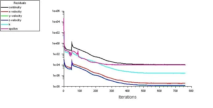
The solution has run up to 760 iterations and seems to have converged after 550 iterations.
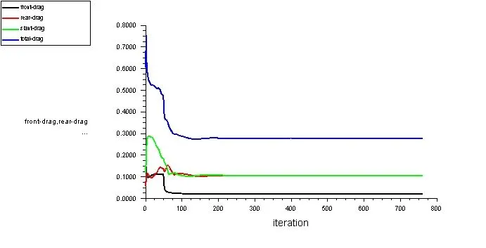
Coefficients of Drag
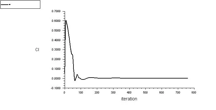
Lift Coefficient
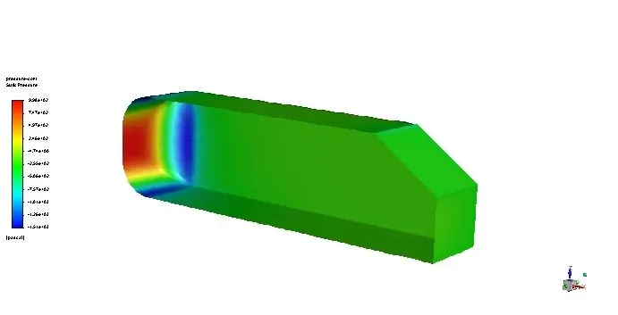
Pressure Contour on Ahmed Body
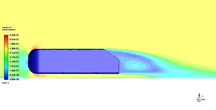
Velocity Contour
Vortices
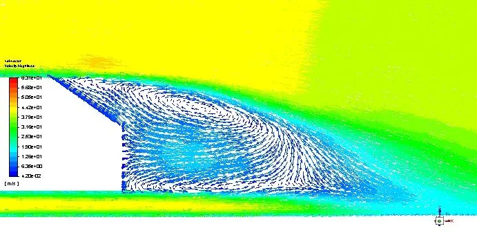
The flow has separated before the slant surface and there are 2 vortices in the low-pressure region adjoining the rear surface and the slant surface.
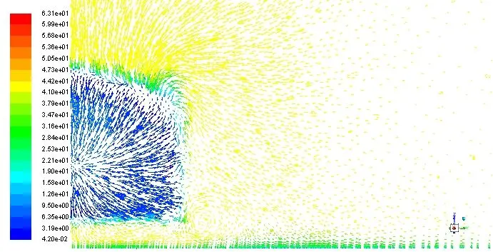
The C-type vortex is not dominant.
Drag and Lift Coefficients
Comparing the numerically obtained and experimental Drag coefficient values.
| Angle of Inclination | Total Coefficient of Drag | Experimental Drag Coefficient | % Error |
| `25^o` | 0.3 | 0.285 | 5 |
Numerically obtained Drag and lift coefficients
| Angle of Inclination | Total Coefficient of Drag | Frontal Coefficient of Drag | Slant Coefficient of drag | Rear Coefficient of Drag | Coefficient of Lift |
| `25^o` |
0.3 |
0.0236 |
0.123 |
0.112 |
0.2239 |
| `30^o` |
0.289 |
0.024 |
0.108 |
0.1162 |
0.056 |
| `35^o` | 0.279 |
0.0232 |
0.109 | 0.1064 |
0.0058 |
Conclusions
- The scaled residuals have converged for `30^o` and `35^o` slant inclinations, but the they are oscillating about a mean value for an inclination of `25^o`.
- The drag and lift coefficients are also oscillating about a mean value for the `25^o` slant inclination, they have converged for `30^o` and `35^o` slant inclinations.
- In the slant inclination of `25^o`, the flow remains attached for some length along the slant surface but then separates. The flow separates at the beginning of the slant surface for `30^o` and `35^o` inclinations.
- The length of the low pressure region in the wake has increased with an increase in the inclination angle.
- Among the two parallel counter rotating vortices in the rear, the distance between them have increased with an increase in the slant inclination angle i.e., the upper vortex has moved upwards due to earlier boundary separation. And the lower vortex has become more flat with an increase in the inclination angle.
- Considering X axis the flow direction, the relative velocity in the Y-Z plane (w.r.t. the flow velocity) has reduced with the increase in the slant inclination angle, This has led to the diminishing C-type vortex with increase in angle.
- There is a 5% error in the numerically obtained compared to experimentally determined value of Drag coefficient for slant angle `25^o`.
- The total Drag coefficient has decreased with increase in the slant angle of inclination. The coefficient of drag of the slant surface has decreased with increase in slant angle.
- The coefficient of lift has decreased noticeably with increase in slant surface angle.