Analysis of flow around a 2-D cylinder
Abstract
External fluid flow analysis of a Bluff body is a classical example in Fluid mechanics. The objective of this simulation is to analyze the characteristics of flow around a 2-D cylinder and study the Von Karman vortex street formation for various Reynolds numbers under transient conditions. The simulation is done for transient condition, Strouhal number is calculated. Once the transient simulation achieves a steady-state, the coefficients of lift and drag are realized over a range of Reynolds numbers.
Introduction
In fluid dynamics, Von Karman vortex street is a periodic pattern of swirling vortices caused by a process known as vortex shedding which is responsible for the unsteady separation of fluid flow around blunt bodies. This phenomenon occurs only for fluid flow over a certain velocity, typically above Reynold’s number of 90. The vortices in the wake region remain uniform for low Reynolds number flow but gradually the wake region becomes turbulent as Reynolds number increases above 105 and subsequently the vortices become chaotic. This phenomenon can be mathematically understood through Computational Fluid Dynamics.
Computational Fluid Dynamics is a branch of fluid dynamics with extensive mathematical modeling of the physical phenomena. This branch is not very accurate but has the capability of modeling fluid flow phenomena better than any other method of analysis. Commercial and opensource software packages are available which can be used to simulate the models. The current analysis is done using one such package called FLUENT.
The equations governing the current analysis are the Navier Stoke's Continuity and Momentum conservation equations for 2-dimensional viscous transient flow.
Continuity equation
`(delrho)/(delt)+rho[(del(u))/(delx)+(del(v))/(dely)]=0`
X Momentum Equation
`(del (rhou))/(del t)+u(del u)/(del x)+v(del u)/(del y)=f_x-1/rho(del p)/(del x)+nu[(del^2u)/(delx^2)+(del^2u)/(dely^2)]`
Y Momentum Equation
`(del (rhov))/(del t)+u(del v)/(del x)+v(del v)/(del y)=f_y-1/rho(del p)/(del y)+nu[(del^2v)/(delx^2)+(del^2v)/(dely^2)]`
In Fluid dynamics, Drag coefficient is a dimensional quantity that is used to quantify the drag or the resistance of an object in a fluid environment. The drag coefficient of any object comprises the effects of two basic contributors to fluid dynamic drag: skin friction and form drag.
Lift coefficient is a dimensional quantity that relates the lift generated to the fluid density, fluid velocity and an associated reference area.
Strouhal number is a dimensionless parameter used to describe oscillating flow mechanisms. For large Strouhal numbers(order of 1), viscosity dominates fluid flow resulting in the collective oscillating movement of the fluid plug. For low Strouhal numbers(order of `10^-4` and less), the high-speed quasi-steady-state portion of the movement dominates oscillation. Oscillation at intermediate Strouhal numbers are characterised by buildup and rapid subsequent shedding of vortices.
Formulae
`L=1/2C_l rho A V_oo^2`
`F=1/2 C_d rho A V_oo^2`
`R_e=(rho*V_oo*D)/mu`
`S_t = (f*d)/V_oo`
L = Lift force, F = Drag force, A = Projected area, `C_d`= Coefficient of drag, `C_l`= Coefficient of lift, `V_oo`= Free stream velocity, `rho`= Fluid density, `R_e`= Reynolds number, `S_t`= Strouhal number, f = frequency of vortex street, D = diameter
Case Set-up
Geometry Creation in Space Claim
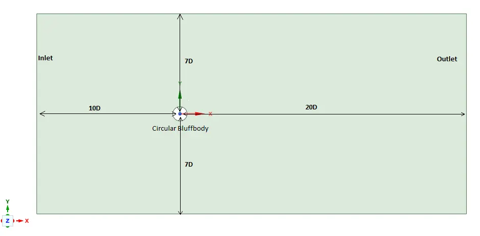
A circle of diameter D=2m is drawn and a virtual rectangular wind tunnel is set up, ranging from 10D in the upstream to 20D in the downstream, 7D above and below the circle. This creates a rectangular surface with a circular hole. This surface denotes the region of fluid flow under study and the circular hole, the wall of the cylinder in a 2-D plane.
Hexa meshing in ICEM CFD
- The created geometry is imported into ICEM CFD, part name creation is done for the geometries, the upstream edge is named INLET, the downstream edge is named OUTLET, the two parallel sides are named SIDE_BOUNDARIES, the circle is named CIRCULAR_BLUFF_BODY. A new part is created to contain all the points.
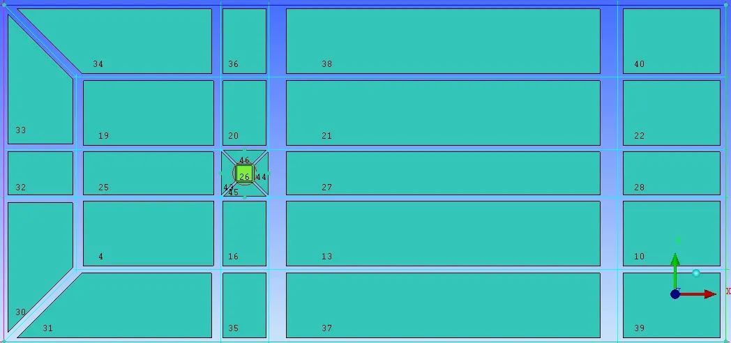
- A 2-D planar block is set up, the vertices and edges are associated with the points and curves respectively, then the block is split at the required places and O-grids are set up.Two O-grids are used for meshing flows with Reynolds numbers 10000 and 100000 and only one is used for the rest.
- The edges of the O-grid around the circle are associated with the circle. Now the block inside the circle is named as a SOLID part and is hidden from the screen.
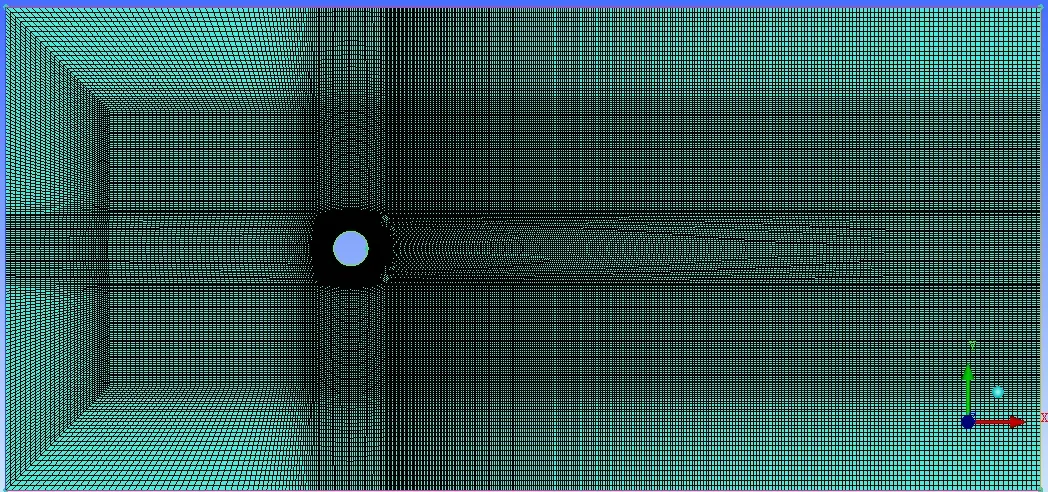
- The pre-mesh parameters near the wall of the circular wall are set by considering the Y+ requirements of the study undertaken and the necessary first cell height is assigned.
- This pre-mesh is converted to an unstructured Hexa-mesh by keeping the SOLID part hidden.
- The boundary conditions are set and the mesh file is saved and exported for processing. The boundary conditions are Velocity Inlet for INLET, Pressure outlet for OUTLET, Symmetry for SIDE_BOUNDARIES, and wall for CIRCULAR_BLUFF_BODY.
Block generation for `R_e`= 100000
Hexa-Mesh for `R_e` = 100000
FLUENT
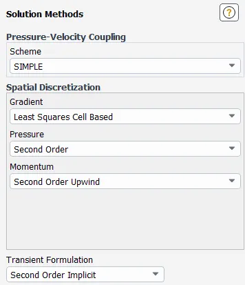
The mesh file is imported into Fluent, flow analysis is done for five different Reynolds numbers i.e., 10,100,1000,10000,100000.
Operating conditions
Atmospheric pressure: 101325 Pa
Outlet Gauge pressure: 0 Pa
Dynamic Viscosity: 1.86 Pa s
Density: 1.125 `kg m^-3`
Diameter: 2m
Flow model: Viscous(laminar)
Case 1: `R_e` = 10
Free stream velocity = 0.00846 m/s
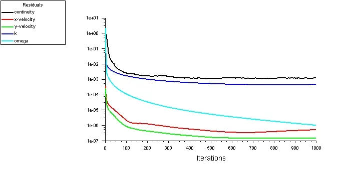
Scaled Residuals
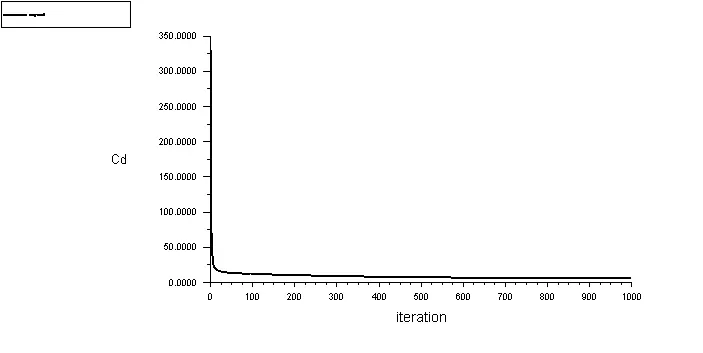
Coefficient of Drag
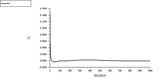
Coefficient of Lift
Velocity Contour
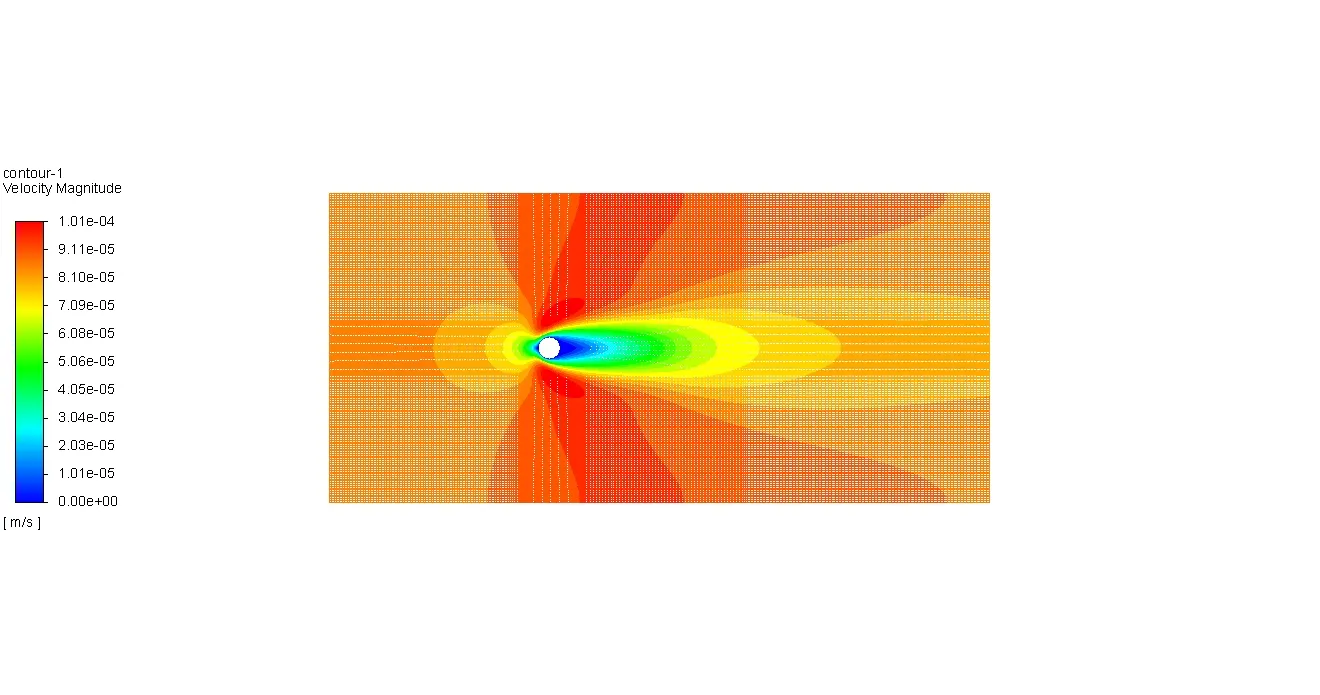
The simulation has attained a steady-state after 700 iterations. The wake region has small vortices immediately next to the cylinder but the flow rejoins as a laminar flow due to the low velocity of the free stream, hence Von Karman street is not formed as vortex shedding does not occur.
Case 2: `R_e` = 100
Free stream velocity = 0.0846 m/s
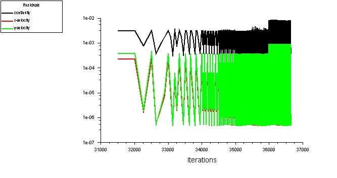
Scaled Residuals
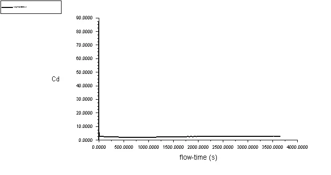
Coefficient of Drag
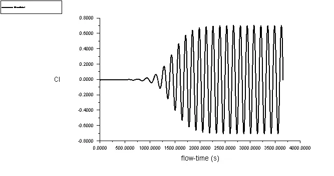
Coefficient of Lift
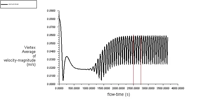
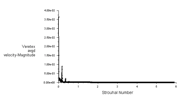
Vertex Averaged Velocity - Magnitude
Strouhal number
Velocity contour
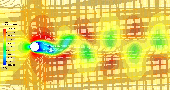
The solution has attained steady-state after 2500 seconds. Vortex shedding has been observed in the wake region, this has formed a Von Karman street. Strouhal number can be calculated and it is observed to be, `S_t` = 0.33.
Click on the link to view the velocity contour animation: https://youtu.be/lzDWxq3f4jM
Case 3: `R_e` = 1000
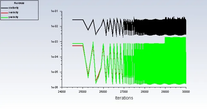
Scaled Residuals
Coefficient of Drag
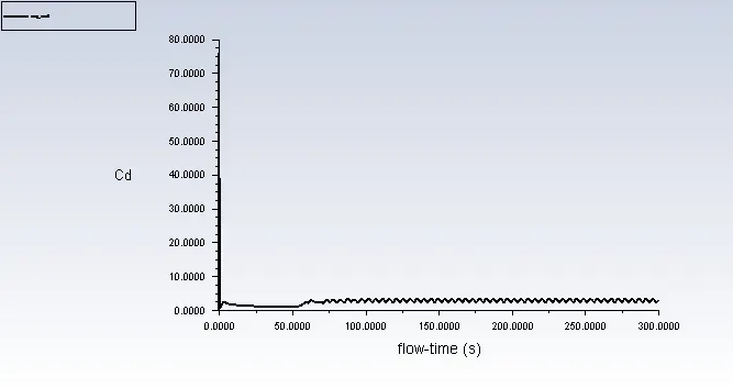
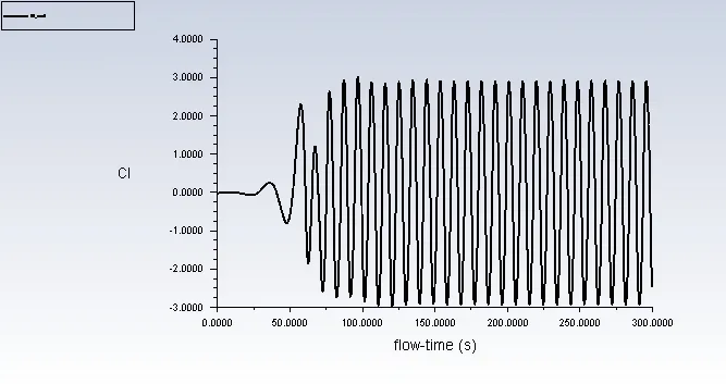
Coefficient of Lift
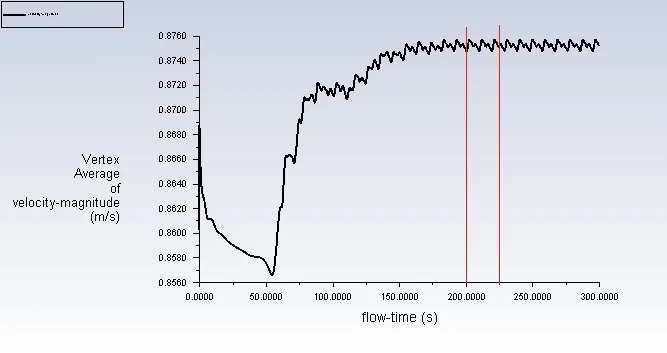
Vertex Averaged Velocity - Magnitude
Strouhal Number
Velocity Contour
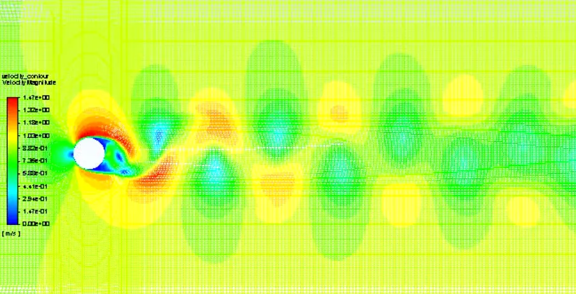
The solution has attained steady-state after 200s. Vortex shedding has been observed which has led to the formation of Von Karman street in the wake region. Strouhal number has been observed to be, `S_t`= 0.2364.
Click on the link to view the velocity contour animation: https://youtu.be/2DYvDoICIVU
Case 4: `R_e` = 10000
Free stream Velocity = 8.46 m/s
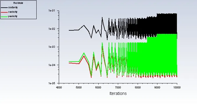
Scaled Residuals
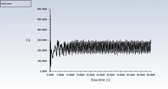
Coefficient of Drag
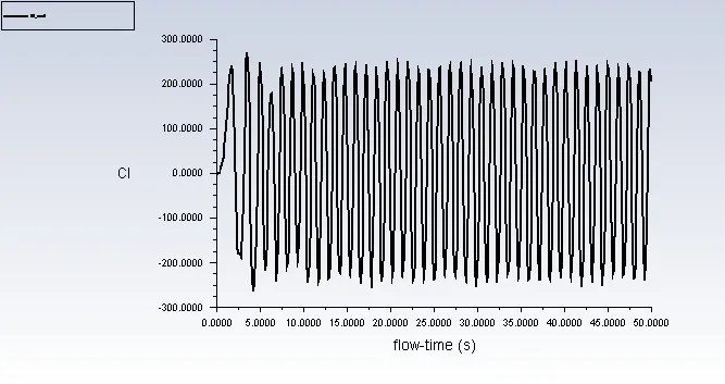
Coefficient of Lift
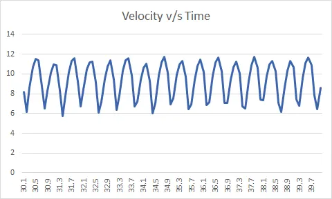
Vertex Averaged Velocity - Magnitude
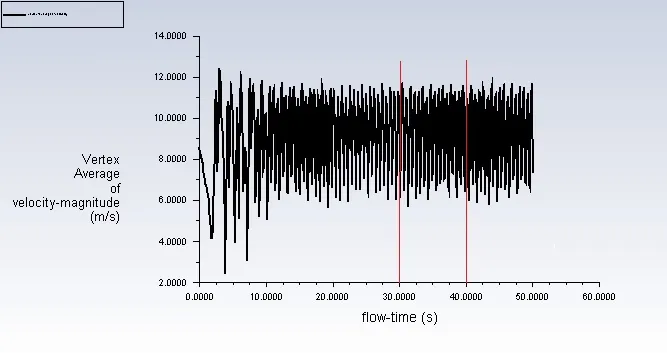
Strouhal Number
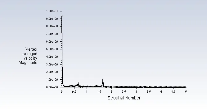
Velocity Contour
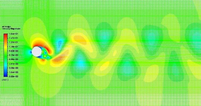
The flow achieves steady state after around 15 seconds of flow. Vortex shedding has been observed which has formed a Von Karman street in the wake region. The Strouhal number is found to be, `S_t` = 0.39
Click on the link to view the velocity contour animation: https://youtu.be/NHvKgeUN9Jc
Case 5: `R_e` = 100000
Free Stream Velocity = 84.6 m/s
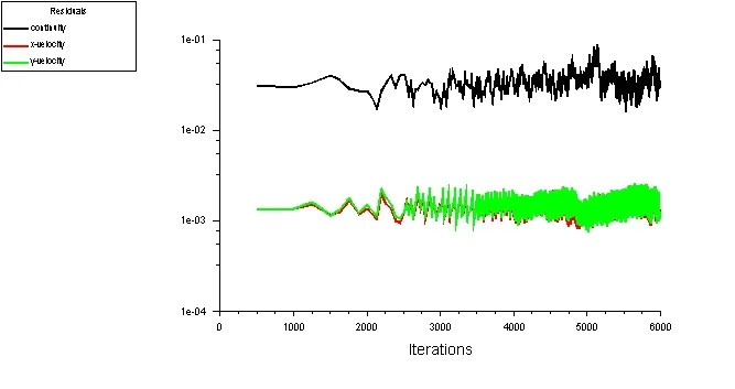
Scaled Residuals
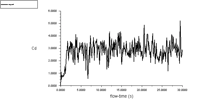
Coefficient of Drag
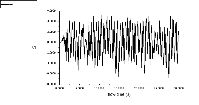
Coefficient of Lift
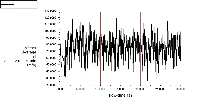
Vertex Averaged Velocity - Magnitude
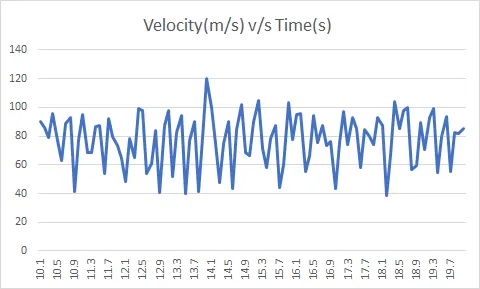
Strouhal Number
Velocity Contour
Velocity Vector
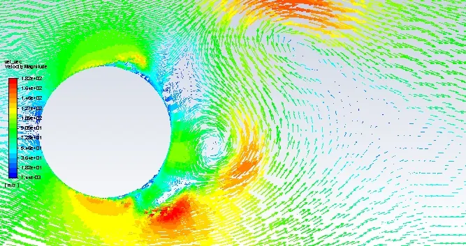
The velocity vector map for `R_e`=100000 shows the low pressure vortices and alternate separation of the Boundary layer from the circular surface.
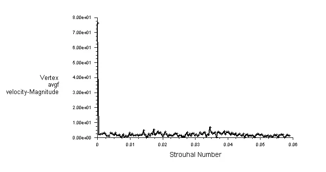
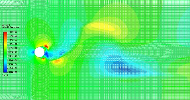
The solution has attained steady-state after 10 seconds. Intense vortex shedding has occurred which has led to the formation of a high frequency Von Karman street in the wake region. The Strouhal number is observed to be, `S_t`= 0.073.
Click on the link to view the velocity contour animation: https://youtu.be/5JrXHhITyMI
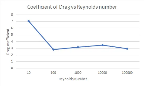
| Reynolds Number, `R_e` | Coefficient of Drag, `C_d` | Coefficient of Lift, `C_l` |
| 10 | 7.1 | 0.000106 |
| 100 | 2.8079 | 0.02615 |
| 1000 | 3.14076 | 0.06516 |
| 10000 | 3.45016 | 0.0273 |
| 100000 | 2.93 | 0.06823 |
Conclusions
- For Reynolds number less than 100 vortex shedding does not occur as the pressure difference between the free stream and the wake region is less. Small vortices are formed in the immediate vicinity of the cylinder but the flow then becomes parallel.
- For Reynolds numbers equal and greater than 100, the pressure in the wake becomes significantly low, hence vortex shedding occurs and forms a Von Karman street but the flow remains laminar in the downstream.
- In flows with high Reynolds number, the pressure difference between the wake and free flow becomes great enough as to suck in the fluid from the free flow to form vortices. This causes the early separation of the boundary layer from the wall surface. Boundary layer separation happens alternatively on opposite sides of the circular bluff body.
- From the drag coefficient vs Reynolds number plot, it has been observed that the coefficient of drag decreases as Reynolds number increases. But an increase in drag coefficient is noticed for `R_e`s 1000 and 10000 but again decreases.