FINAL TEST
Questions based on PFI Engine:
Q1. What is the Compression ratio for the engine ?
Compression ratio of an engine is given by the ratio of maximum air volume inside the cylinder to the minimum air volume inside the cylinder. The maximum volume inside the cylinder will be the volume displaced by the piston and the clearance volume. The minimum volume of the cylinder will be the clearance volume.
Thus the compression ratio can be written as `"displacement volume + clearance volume"/"displacement volume"` = `(V_d + V_c)/V_c` = `V_max/V_min`
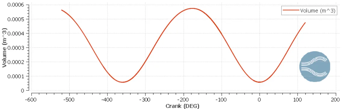
From the above plot between air volume inside the cylinder vs crank angles, the maximum and minimum volumes of the air can be obtained.
`V_max`= `5.742*10^-4``m^3`
`V_min`=`5.702*10^-5``m^3`
Therefore compression ratio = `V_max/V_min` = `(5.742*10^-4)/(5.702*10^-5)` = 10.07
Q2. Modify the compression ratio for this engine to 10.3 without changing geometrical parameters.
The compression ratio of the engine is given by the ratio of maximum air volume inside the cylinder to the minimum air volume inside the cylinder which is `"displacement volume + clearance volume"/"displacement volume"` = `(V_d + V_c)/V_c` = `V_max/V_min`.
As we can see from the above expression for the compression ratio, it depends upon the displacement volume of the piston and the clearance volume. To change the compression ratio of the engine either the displacement volume or the clearance evolume has to be changed.
To change the displacement volume, either the connecting rod length or the dimensions of the cylinder has to be changed. To change the clearance volume, the cylinder head has to be placed at a higher level than before or the cylinder head has to be shfted upwards. So, the compression ratio cannot be modified without changing the geometrical parameters.
So, modifying the compression ratio to 10.3 by changing the geometric parameters.
i) By changing the displacement volume while keeping the clearance volume constant.
Clearance volume = minumum volume = `5.702*10^-5``m^3`
Modified compression ratio = `(V_d + V_c)/V_c`
10.3= `(V_d + 5.702*10^-5)/5.702*10^-5 `
Therefore `V_d` = 0.0005303 `m^3`
ii) By changing the clearance volume while keeping the displacement volume constant.
Displacement volume = `V_d`=`V_max - V_min` = `5.742*10^-4``m^3`- `5.702*10^-5``m^3`
= 0.00051718 `m^3`
Modified compression ratio = `(V_d + V_c)/V_c`
10.3 = `(0.00051718 + V_c)/V_c`
`V_c`= `0.00051718/9.3`
= `5.56*10^-5`
Q3. Calculate Volumetric Efficiency for this engine
The volumetric efficiency of an IC engine is given by the ratio of the volume of the air drawn into the cylinder during the suction stroke to the volume displaced by the piston.
Thus it can be expressed as volumetric efficiency = `V_a/V_d`
The displacement volume is `V_d`=`V_max - V_min` = `5.742*10^-4``m^3`- `5.702*10^-5``m^3`
= 0.00051718 `m^3`
The air inside the cylinder is considered as an ideal gas. Now, the ideal gas equation can be used to calculate the volume of air drawn inside the cylinder during the suction stroke.
Ideal gas equation for air is `P_a*V_a = m_a*R_a*T_a``
The pressure of the air during the suction is atmospheric pressure = `P_a` = 101325.0 Pa.
The temperature of air is atmospheric = `T_a` = 300 k.
The gas constant for air is `R_a` = 287 `J/(kg.k)`.
Mass of the air from the below plot of mass of air vs crank angle is given by `m_a` = 0.0005342 kg.
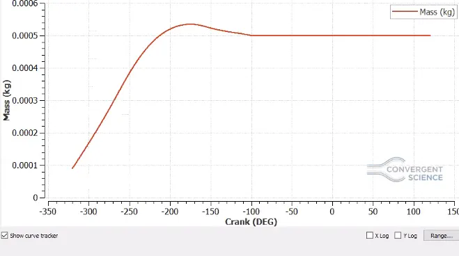
Therefore `V_a` = `(m_a*R_a*T_a)/P_a`
= `(0.0005342*287*300)/101325.0 `
= 0.00045392 `m^3`
Now, Volumetric efficiency = `V_a/V_d` = `0.00045392/0.00051718`
= 0.877682 = 87.7682 %
Q4. Measure the air mass flow rate for this engine in kg/s
Mass of the air from the below plot of mass of air vs crank angle is given by = 0.0005342 kg. This mass is flowing in side the engine for one cycle.
Therefore we have mass flow per cycle = 0.0005342 `"kg"/"cycle"`
The rpm of this engine is 3000
Number of revolutions in 1 cycle= 2
Therefore number of cycles per minute is 1500
Number of cycles per second is `1500/60` = 25
Therefore mass flow per second = mass flow per cycle x number of cycles per second
= 0.0005342 x 25
= 0.013355 `"kg"/s`
Q5.Why is the cell count varying during the simulation ?
The cell count varies primarily due to the compression and expansion strokes. It also varies due to adaptive mesh refinement and fixed embedding. The adaptive mesh refinement refines the cells where there is a difference in between the quantities being measured among the adjacent cells the difference being dependent on the sub-grid scale criterion. If the difference is more than the sub-grid scale criterion, then the cells get refined. Fixed embedding refines the cells in particular specified parts of the geometry where the data is required to be captured accurately. This embedding may be permanent or cyclic.
Q6. In a real engine, valves are in contact with the cylinder head but while running simulation, there is a small gap
a)Why?
A small gap is maintained between the cylinder head and the valves during the simulation because to create and remove the disconnect triangles for events which are the opening and closing of the valves during the different strokes.
b)What happens if this gap is big ?
If the gap is big then the air flow inside the cylinder during the suction stroke will be suddenly more as the disconnect triangle will suddenly allow the air to enter the cylinder. This leads to a deviation from the real engine where the air injected inside the cylinder is not aburpt but depends upon the opening of the vinlet valve. Thus to make the simulation more realistic, the gap is kept small.
Q7. How many seconds does combustion last in this case ?
The duration of combustion in one cycle is 240 degree crank angles. This can be obtained from the engine performance calculator.
So, converting the duration of combustion from degrees to seconds.
The rpm of engine is 3000.
In one revolution the degrees of the rotation of the engine per minute is 3000 x 360 = 1080000 degrees.
Therefore, the degrees of rotaion per second of the engine is `1080000/60` = 18000 degrees.
Therefore, time for which the combustion lasts = `"degree of crank angles of combustion"/ "degree of rotation per second of the engine"` = 240/18000 = 0.0133 seconds.
Questions based on DIESEL Engine:
Q1. What is an advantage of SECTOR Simulation ?
The sector simulation is a simulation which is run by using a sector of the actual geomentry of the engine. This reduces the time of the simulation as smaller geometry is involved which reduces the number of cells for computation. In the diesel engine simulaton, the cylinder head and the valves and the ports of the IC engine are not present so that the compression stroke and the expansion stroke can be simulated thoroughly. Thus if the geometry is symmetric the sector simulation helps to reduce the time of simulation.
Q2. When will the sector approach not work ?
The sector approach does not work when the geometry is not symmetric. This is because the unsymmetric geometries cannot create a part which can represent the geometry when the identical sectors are joined together to form the geometry again. It also does not work when the geometry has an inlet and outlet. If the geometry has an inlet and an outlet. The geometry if it has an inlet and an outlet, a sector cannot represent the geometry as some of the properties cannot be obtained correctly.
Q3. How to choose Start Crank Angle (SCA) and End Crank Angle (ECA) for a sector simulation ?
In a sector simulation the strokes which are simulated are compression and expansion stroke. So, the Start Crank Angle (SCA) can be choosen as the start of the compression stroke and the End Crank Angle (ECA) can be choosen as the end of the expansion stroke. If the start of the suction stroke is taken as 0 degree crank angle, then the start of the compression stroke becomes 180 degree crank angle and the end of the expansion stroke becomes 540 degree crank angles. So, the the Start Crank Angle (SCA) is 180 degree crank angle and the End Crank Angle (ECA) is 540 degree crank angle.
Q4. Can we convert the PFI case into a SECTOR case? Explain your answer ?
No, the PFI case cannot be convereted into a sector case because it has intake and exhaust ports and the injectfion point is at the intake port which cannot be divided into a sector element which can represent the entire PFI geometry. The PFI case has an inlet and outlet which cannot allow a sector simulation as the sector simulation is suited for closed and symmentric geometry. In this case, all the four strokes are to be performed which requires the PFI case to remain open with valves and ports.