FINAL TEST
Questions based on PFI Engine:
Q1. What is the Compression ratio for the engine?
The compression ratio is the ratio between the volume of the cylinder and combustion chamber in an internal combustion engine at their maximum and minimum values. A fundamental specification for such engines, it is measured two ways: the static compression ratio, calculated based on the relative volumes of the combustion chamber and the cylinder when the piston is at the bottom of its stroke, and the volume of the combustion chamber when the piston is at the top of its stroke. The dynamic compression ratio is a more advanced calculation which also takes into account gasses entering and exiting the cylinder during the compression phase. A high compression ratio is desirable because it allows an engine to extract more mechanical energy from a given mass of air–fuel mixture due to its higher thermal efficiency. This occurs because internal combustion engines are heat engines, and higher compression ratios permit the same combustion temperature to be reached with less fuel, while giving a longer expansion cycle, creating more mechanical power output and lowering the exhaust temperature. In a piston engine, the static compression ratio(CR) is the ratio between the volume of the cylinder and combustion chamber when the piston is at the bottom of its stroke, and the volume of the combustion chamber when the piston is at the top of its stroke. It is therefore calculated by the formula

Where:
 = displacement volume. This is the volume inside the cylinder displaced by the piston from the beginning of the compression stroke to the end of the stroke.
 = clearance volume. This is the volume of the space in the cylinder left at the end of the compression stroke.
We can also find the Compression using the Volume plot of the simulated results.
Compression ratio = Max. Volume/ Min. Volume
Compression ratio = 0.000572195/5.7029e-5
Compression ratio = 10.033
Q2. Modify the compression ratio for this engine to 10.3 without changing geometrical parameters.
- Current CR = 10.033

- b = 0.086m
- s = 0.09m
- Vd = 5.2279e-4; CR = 10.33
- Vc*Cr = Vd +Vc; Vc = Vd/(CR-1)
- Vc = 5.603e-5
To modify the compression ratio without changng the geometrical parameters, Two methods can be adapted, either by changing the value of Vd or Vc:
CRn = 10.3(CR value needed to modify)
By Changing Clearance Volum(Vc)
- CRn = 10.3
- Vd = 5.2279e-4m^3
- Vc = Vd/(CRn-1)
- Vc = 5.6213e-5m^3
By Changing Displacement Volume(Vd)
- CRn = 10.3
- Vc = 5.603e-5m^3
- Vd = (CRn*Vc)-Vc
- Vd = 5.209e-4m^3
Q3. Calculate Volumetric Efficiency for this engine
The volumetric efficiency ηv [-] is defined as the ratio between the actual (measured) volume of intake air Va [m3] drawn into the cylinder/engine and the theoretical volume of the engine/cylinder Vd [m3], during the intake engine cycle.
- Volumetric Efficiency(ηv)=Va/Vd
- Vd = 5.2279e-4 m^3
- Va = Actual volume
- Va = (m*R*T)/P
- Mass into engine(m) = 0.00050051Kg
- Universal gas contant(R) = 8.3144598 J/k
- Temperature(T) = 293K
- Pressure(P)= 101325pa
- Va = 4.1538e-4 m^3
- Volumetric Efficiency = 4.1538e-4/5.2279e-4
- Volumetric Efficiency = 0.7945 ==> 79.45%
Q4. Measure the air mass flow rate for this engine in kg/s
- Mass of air into engine = 0.00050051627
- Engine Speed = 3000RPM = 50 RPS
- Mass flow Rate = 0.02502Kg/s
Q5.Why is the cell count varying during the simulation?
Total cell coout varies during the simulation. This is because of the application of Advanced Mesh Refinement(AMR) and Fixed embedding. In numerical analysis, adaptive mesh refinement (AMR) is a method of adapting the accuracy of a solution within certain sensitive or turbulent regions of simulation, dynamically and during the time the solution is being calculated. When solutions are calculated numerically, they are often limited to pre-determined quantified grids as in the Cartesian plane which constitute the computational grid, or 'mesh'.In this simulation, We chose AMR with respect to temperature and Velocity. Thus the tmeperature and velocity gradients controls the mesh in the governing region to scale with level provided. The other thing that controls the mesh is fixed embedding over the region, injectors and shapes. IF the fixed embedding is permanant there wont be change in cell count during simulation but cyclic type fixed embedding with affect the cell count during the simulation.
Q6. In a real engine, valves are in contact with the cylinder head but while running simulation, there is a small gap
- WHY?
- What happens if this gap is big?
In a real engine, valves are in contact with the cylinder head but while running simulation, there is a small gap because it allows the converge to create disconnect triangle covering the gaps. These disconnect triangles are controled be events which open and close the flow through the valve whereas in real engines the valves are opened and closed using spring through cam motion. By this the combustion occurs inside the chamber stays inside with respect to the events.
If this gap is big,the accuracy of the results is affected. If the too big, the valve will stay high affecting the volume of combustion area which is diiferent than the original volume and accuracy in calculation is affected.
Q7. How many seconds does combustion last in this case?
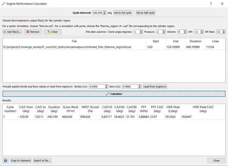
From the engine perfomance calculator:
- Combustion duration is 240.199 deg.
- Crank speed = 3000RPM = 50 RPS
- No. degree per second = 18000
- Time for 1 deg = 5.55e-5
- Time for combustion = 5.55e-5 * 240.199 = 0.0133s
Questions based on DIESEL Engine:
Q1. What is an advantage of SECTOR Simulation?
The major advantage of Sector simulation it the computation efficiecy in simulation time and energy. This is because we are dividing the the whole geometry into sector and simulate where we neglect the Valves and port. Thus in this case the number of cells needed is reduced drastically which eventually reduce the computational time. this simulation also reduces the complexity in boundary condition, region,events, valves and ports. This leads the simulation to higher efficiency.
Q2. When will the sector approach not work?
The sector approch does not work when there is a need for open cycle simulation. In an open cycle simulation, the intake and exhaust ports needs model and the positon does not support the the symetric nature of sector to accomodate them. Thus any geometric design in chamber that doesnot allow you to create a symetric sector does not work in sector approach.
Q3. How to choose Start Crank Angle (SCA) and End Crank Angle (ECA) for a sector simulation?
For a sector simulation, the Start Crank angle is the beginning of the simulation and the End Crank angle is the end of the simulation. Thus the Start Crank Angle must be the beginning of Compression stroke and the End Crank Angle must be end of expansion stroke.
Q4. Can we convert the PFI case into a SECTOR case? Explain your answer?
The PFI case cannot be coverted into a sector because its ia an open cycle simulation. Sector model will be ineffective when we use for open cycle engine simulation. In an open cycle simulation, the intake and exhaust processes needs to be modeled and in a sector we cannot accomodate the ports. Sector case simulation are simulation of a small portion of axisymetric combustio region best suited for the computational calculation of efficiency of cumbustion. Whereas in PFI case we study everything fro fluid flow to ignition to exhuast which is not possible in sector case.