Final Project: Electric Rickshaw modelling
Aim : Design of an Electric Rickshaw using MATLAB Simulink.
General detail of E-Rickshaw i.e Basic
- Battery Type Lithium Ion 330 V
- 75Ah
- Vehicle kerb weight 260 kgs
- Load capacity 340 kgs
- Vehicle speed 7 kmph
- Driving range 140 km (160 Ah)
- No of wheels per axel 2
- Frontal Area 91m
- Drag coefficient 5
- Wheel radius 306m
- Vertical load 3000 N
- Nominal Voltage 330 V
- Rated Capacity 75 Ah
- Initial SOC % 100
- Internal Resistance 5 ohm
*Vehicle Body Subsystem Model
Motor will produce the rotational output which will give to the vehicle body and transmission system. Rotational output is taken by the gear system here to maintain the constant speed throughout the transmission without any loss in speed from the motor to tires.
*Vehicle Body Parameters
Vehicle body mass, Centre of gravity distance values and aerodynamic drag variables are modified.
Pitch dynamics are kept ON with other variable values as default values.
Photos uploaded in PDF
Connection A is the mechanical rotational conserving port for the wheel axle. Connection H is the mechanical translational conserving port for the wheel hub through which the thrust developed by the tire is applied to the vehicle. Connection N is a physical signal input port that applies the normal force acting on the tire. The force is considered positive if it acts downwards.
Connection S is a physical signal output port that reports the tire slip. Optionally expose physical signal port M by setting Parameterize by to Physical signal Magic Formula coefficients. Physical signal port M accepts a four element vector corresponding to the B, C, D, and E Magic Formula coefficients.
*Vehicle body
This block basically represents a two-axle vehicle body in longitudinal motion. The block accounts for - body mass, aerodynamic drag, road incline, weight distribution between axles due to acceleration road profile.
Here, the connection H is the mechanical translational conserving port hub. NF & NR correspond to the output ports for nomral reaction forces on front axle and rear axle wheels respectively.
Connection V represents the actual output translational velocity of the vehicle. beta is the road inclination angle & W corresponds to the headwind speed (headwind - direction opposite to that of vehicle). The gross weight is given to be 600 kg.
*DC motor ⚙️
TheMotor controller will get input from the longitudinal driver. Its tasks are to control the speed of the motor and drive according to the input of the driver. Majorly motor controlled we designed had two main parts named PWM voltage generator and H-Bridge.
Input 1 is getting from the accelmd of a longitudinal driver and it is given to a controlled voltage source block where it is input to the controlled PWM voltage. Controlled PWM voltage will generate a PWM signal in such a way that H-bridge will generate the required voltage to operate the DC motor for the given driver input.
and will operate only two at a time respectively to the input of the signal from the PWM block.
When deceleration occur this Hbridge will give an output from the positive and negative terminals of it. These negative & positive terminals are later connected to the DC motor and battery. All these components are the simscape electrical components so they need a connection to the solver configuration block which helps to solve the simulation.
*Temperature sensor 🌡️
This block measures temperature in a thermal network. There is no heat flow through the sensor. The physical signal port T reports the temperature difference across the sensor.
The measurement is positive when the temperature at port A is greater than the temperature at port B.
🔋 Battery
The battery is required to power the controller and motor. The controller uses the battery power according to produce the input given by the motor to obtain maximum speed. The battery is also used to power every electrical component in the vehicle.
The Battery block implements a generic dynamic model that represents most popular types of rechargeable batteries.
*Battery State of Charge
State of charge is the percentage or level of battery presents after certain travel or consumption of battery charge by the vehicle.
In the designed vehicle battery charge or state of charge is calculated by the giving it to the rate transition and then to gain where 1/(nominal battery capacity) then to a discrete-time integrator and it will get minus from the 1 as it is considered a 100% of battery and it is multiplied with 100 to get percentage of battery.
The majority of blocks are simscape blocks where physical to simulink converter is used to convert the physical signal from simscape block to simulink signal.
*Controlled Current Source
The Controlled Current Source block converts the Simulink input signal into an equivalent current source. The generated current is driven by the input signal of the block. The positive current direction is as shown by the arrow in the block icon.
We can initialize the Controlled Current Source block with a specific AC or DC current. If we want to start the simulation in steady state, the block input must be connected to a signal starting as a sinusoidal or DC waveform corresponding to the initial values.
Double click controlled current source and from drop down menu of measurement select current.
Signal output will connect with scope by adding current signal to it.
*BUS Selector
The Bus Selector block outputs the signals you select from the input bus. The block can output the selected elements separately or in a new virtual bus.
Here just we have mange the output and connect with different Scope Block.
*PowerGUI
The powergui block allows us to choose one of these methods to solve your circuit.
Continuous, which uses a variable-step solver from Simulink
Discretization of the electrical system for a solution at fixed time steps.
*The Simulink Model of Electric Rickshaw
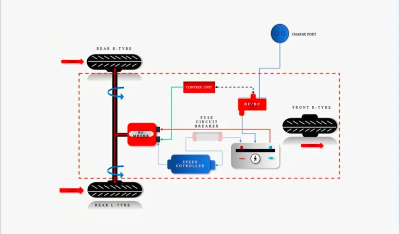
A current flows to DC Motor from the battery through the DC-DC power converter to drive the motor. The required voltage will be controlled in the controller. The Controller will follow the given drive cycle reference and run the motor in the required rotation per minute.
Then the motor power is transmitted to the wheels of a vehicle through the gear box. and the controller will take the vehicle speed and compare and control.
*Conclusion
Here I have compromised with the temperature of Motor and controller to achieve vehicle speed is near to reference speeds. Since I haven’t used any cooling system in the model. In the real time application, the motor temperature is less than 100 C.
In the real time application, the motor, battery & controller temperature is controlled by air cooling. Hence, the temperature of this components is not increased to this extent.
Hence, Created a Matlab model of an Electric Rickshaw by using Li-ion battery, PM Brushed DC Motor.
Battery powered Rickshaw will be the most popular mode of transport in the future.
Waveform and diagrams are uploaded in PDF.
Model