Final Project: Electric Rickshaw modelling
So in the question it was given to,
Create a detailed MATLAB model of an electric rickshaw (three wheel passenger vehicle) as per details below:
Rear wheels driven by PM brushed type motor
Assume efficiency points of motor controller and motor
Make an excel sheet of all input and assumed data
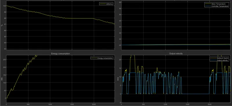
Results: For any three standard driving cycles show energy consumption, temperature rise of motor and controller for 100 km constant speed driving at 45 kmph.
So in this answer section we are going to discuss about the
- Software used
- Block Diagram Study
- Design Approach
- Parameter and Subsystem Study
- Result and conclusion.
1. Software used - The software used to develop this model is MATLAB R2020b (SIMULINK). MATLAB is such a flexible tool to develop the physical systems and applications and to simulate them.
2. Block Diagram Study-
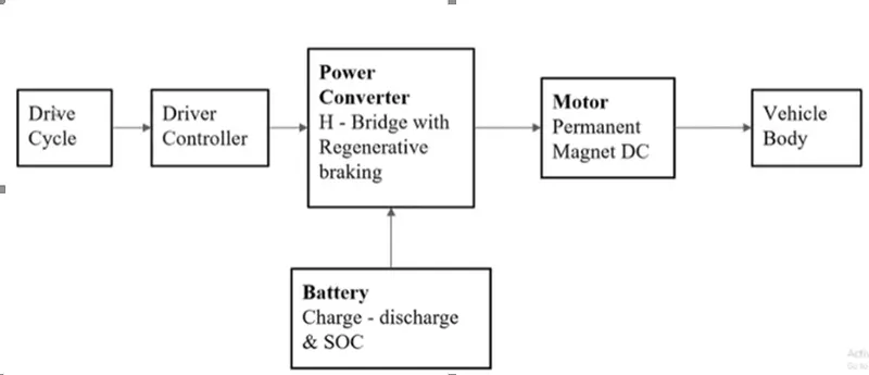
- DRIVE CYCLE- It is nothing but the driver's input to the vehicle. Generally it is a Speed vs Time Graph. There are already some default drive cycles available in the 'drive cycle' block of the SIMULINK. And there are some standard cycles such as FTP75, Artemis driveway 150 and 130, WOT (Wide Open Throttle) which are mostly used as the testing Drivecycles by many of the companies. Customised drive cycles can also be given through the Excel Spreadsheet
- Drive Controller- A parametric longitudinal speed tracking controller is used for generating normalized acceleration and braking commands based on reference and feedback velocities.The controller uses the battery power according to produce the input given by the motor to obtain maximum speed.
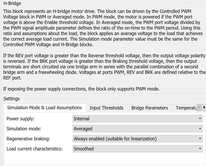
- Power Converter (H-Bridge)- It is used as a DC-DC Converter. This H-Bridge circuits are often used in robotics and other applications such as in EV's etc.
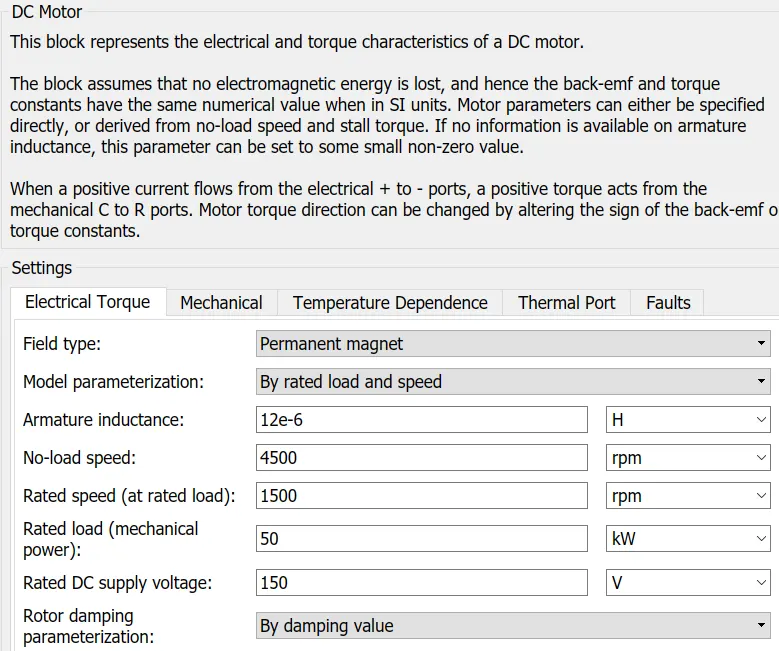
- Motor (PM brushed DC motor)- This block represents the electrical and torque characteristics of a DC motor includes Thermal port to sence the temperature of Motor. Motor parameters can either be specified directly or derived from no-load speed and stall torque. Other types of motors can be used such as Brushless DC Motor etc.
- Battery- The battery is required to power the controller and motor. The controller uses the battery power according to produce the input given by the motor to obtain maximum speed. The battery is also used to power every electrical component in the vehicle.
- Vehicle Body- Nothing but the chassis on Wheels. Vehicle Body block is available in SIMULINK. It is available in Simscape / Driveline / Tires & Vehicles.
3. Design Approach- The approach should always start from the chassis and then tires and selection of the motor and this is because we can get to know about the loading conditions and according to that the selection of the tires, the motor and the battery can be done.
Chassis >> Tyres >> Gearbox>> Motor >> Battery >> controller.
4. Parameter and the subsystem study-
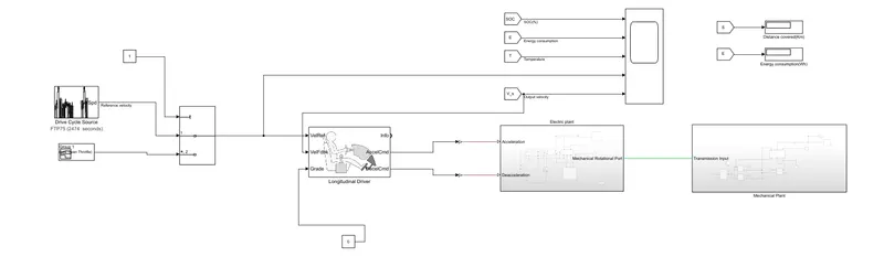
here the blocks built and taken are
- Drive cycle
- Longitudinal Driver controller
- Electric Plant
- Mechanical Plant
These are the main blocks considered now let us get into each of them and discuss the subsystem much in detail.
- Mechanical Plant-
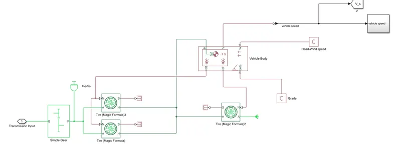
If we look at the port configurtion of each and every block used,
Vehicle Body
- beta: Physical signal input port of road inclination angle
- W: Physical signal input port of headwind speed
- H: Mechanical translational conserving port associated with the honzontal motion of the vehicle body
- NF: Physical signal output port of Front normal wheel force
- NR: Physical signal output port of Rear normal wheel force
- V: Physical signal output port of vehicle velocity
Tire
- N: Physical signal input port that applies the Normal force acting on the Tire
- A: Mechanical rotational conserving port for the wheel Axle
- H: Mechanical translational conserving port for the wheel Hub
- S: Physical signal output port that reports the tire Slip
Simple Gear
- F: Follower
- B: Base
The gear output is given to axels of Rear tires, in the circuit it is shown that gear is connected to Rear wheels (as in the question, it is clearly given that it is rear driven) and front tire is free to rotational motion, thus vehicle moves forward. N is the normal force caused by the tires and it is given to the vehicle body normal force port. The vehicle body has an H-Hub, S- Tire slip, N- Normal force, A- axel connection, wind velocity, inclination angle of the surface.
The tires hub is connected as a common node to the vehicle body. The vehicle body wind velocity is connected to a constant block and the beta-inclination angle is connected to another constant block where we can assign wind velocity and inclination angle as per requirement. Velocity is the output port where we can get at which speed the vehicle is moving. The velocity is taken out to the get the distance travelled and state of charge.
The parameters given to the vehicle body,
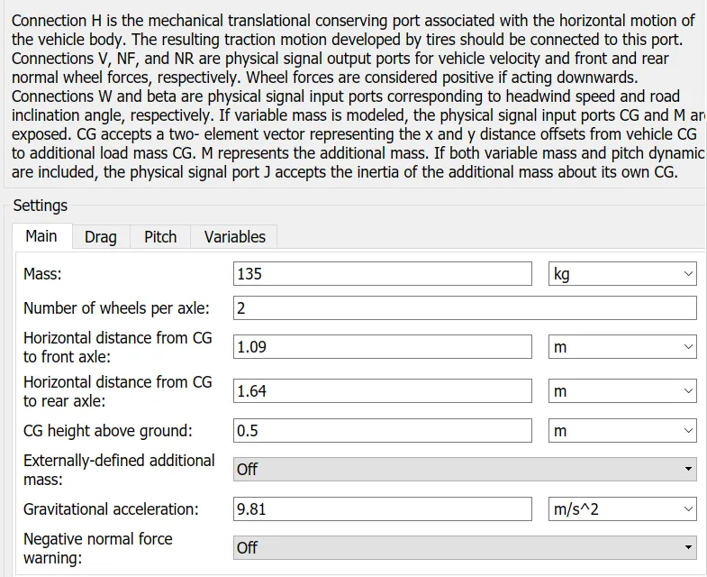
the drag and the pitch values call be given according the aerodynamic resistance and the frictional losses calculations.
And for the tire and the Gear Box
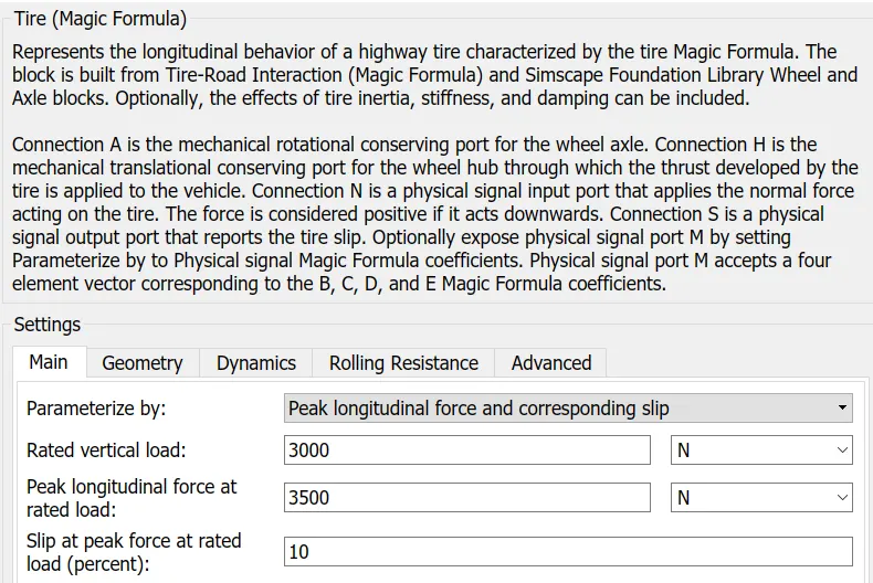
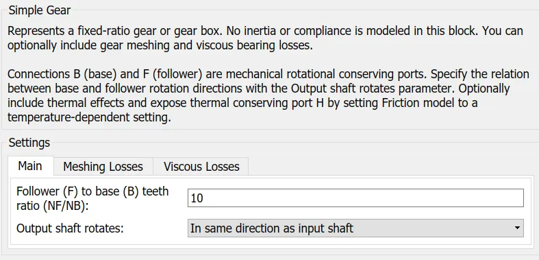
- Electric Plant-
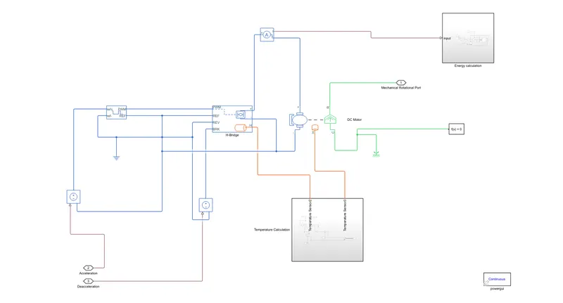
- Motor Parameters-
- H-Bridge-
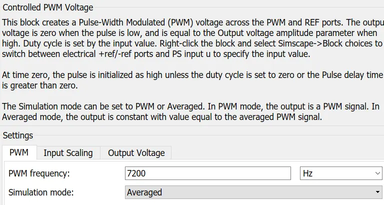
- Controlled PWM Voltage Block-
- Temperature Sensor-
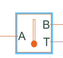
This block measures temperature in a thermal network. There is no heat flow through the sensor. The physical signal port T reports the temperature difference across the sensor. The measurement is positive when the temperature at port A is greater than the temperature at port B.
- Battery, SOC and Energy Consumption-
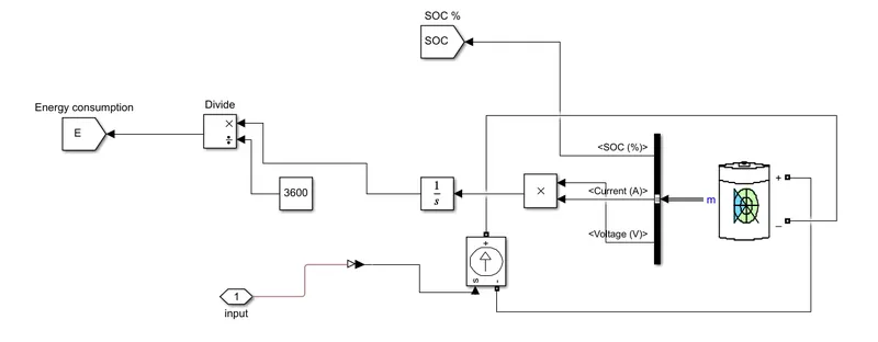
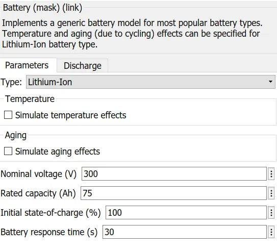
Battery Parameters are -
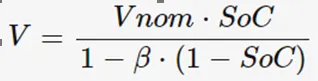
State of Charge - (SoC)-
SoC is the percentage or level of battery presents after certain travel or consumption of battery charge by the vehicle. In the designed vehicle battery charge or SOC is calculated by the giving it to the rate transition and then to gain where 1/(nominal battery capacity) then to a discrete-time integrator and it will get minus from the 1 as it is considered a 100% of battery and it is multiplied with 100 to get percentage of battery.
Energy Consumption-
It is given by the Power integrated with time and It as it is given in kWhr the time should be considered as 3600 seconds.
- Controller parameters-
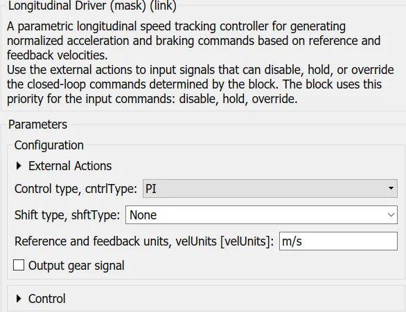
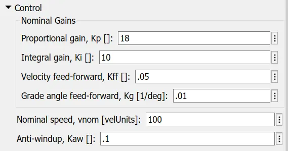
The same as the PI Controller.
5. RESULTS-
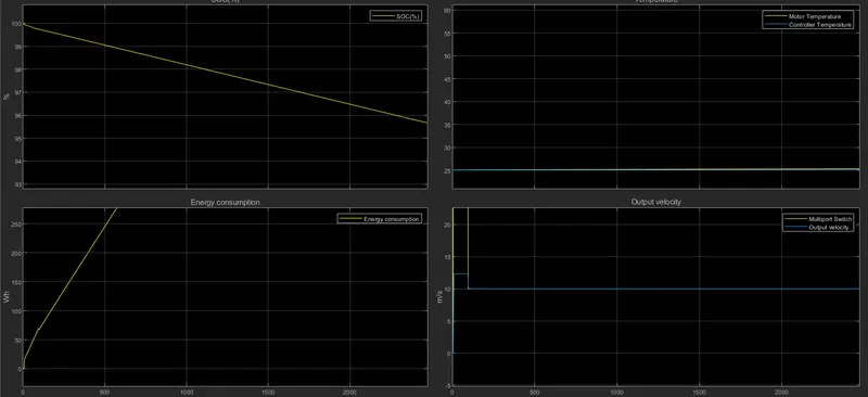
Used three different CYCLES
1. FTP75
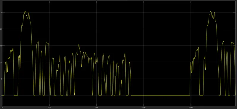
Sample time is 2474 Seconds
2. WOT