Final Project: Electric Rickshaw modelling
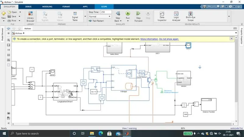
- To create a matlab model of electric vehicle we need to work out from mechanical part and then to electrical part. In mechanical parts, I have used for tires with magic formula for these tires they have 4 connections 1inputs and two outputs. These are from simcape driveline not from powertrain blockset.
- The inputs are normal force and magic formula coefficient the output is slip which is a physical signal, other one is axle. A set of two tires are connected using the axle. The hub port of all the wheels are connected to a block called vehicle body.
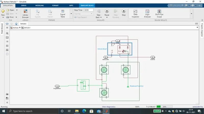
- Earlier we have connected two wheels with an axle let us consider a set of one wheel as front wheel fpr rikshaw and the next set as rear wheels. Front set of wheels are connected to NF and the rear set of wheels are connected to NR off vehicle body block. For this vehicle body block we can give wind velocity, road gradient also as inputs but for time being we are not considering any wind velocity or gradient. All other vehicle body parameters are kept same.
- Now we have considered our vehicle as a front wheel drive show I have connected the drive system to the front wheels to gearbox I haven’t adjusted the gearbox ratio by default it is 5. I have considered this whole as a subsystem so that our rest of the model can be seen clearly.
- Now the input shaft of gearbox he is connected to a DC motor The DC motor we have choosen is a permanent magnet self excited . The motor parameters are given by rated load and speed here we have chosen a 80 kilowatt motor with a rated voltage of 300 volts. No load speed is 16000 rpm and full load speed 15000 rpm. The motor is also give a thermal port
- This motor is driven by a H bridge driver with our supply parameters selected as internal simulation mode is changed from pwm to averaged because to decrease the simulation time in order to take regenerated breaking into picture we have enabled it This H bridge power connections are connected to motor through a current sensor. This H bridge has four control signals which are pwm, reference reverse and brake. we are not using reverse application in this model so we have connected it to electrical reference. H bridge driver thermal port is also activated.
- Controlled pwm voltage generator block is used to generate pwm signal. This pwm block output is connected to H bridge. The input for this pwm block is given from longitudinal driver block.
- A longitudinal driver block (from powertrain block set) is a blog that replicate actual driver it has three inputs and three outputs and control mode is set as PI. The output of this blog are acceleration and deceleration commands & these commands are given to a controlled voltage source which in turn triggers pwm for acceleration commands and for deceleration commands directly the break input of H bridge. The inputs for this block are vehicle reference and feedback. This blocks runs as per reference speed Vs time plot or drive cycle and continuously checks with the feedback received from vehicle body block. Then it gives the output as acceleration commands and deceleration commands to the extent upto to a level that error obtained is minimal.
- Drive cycle block is used to give vehicle reference to our longitudinal driver block and you can select different drive cycles from this block .In order to check weather vehicle is following even drive cycle or not, vehicle feedback input is also taken. This feedback is provided by vehicle body blog. Both vehicle reference and vehicle feedback are connected to a scope to check weather the given drive cycle please followed by vehicle or not.
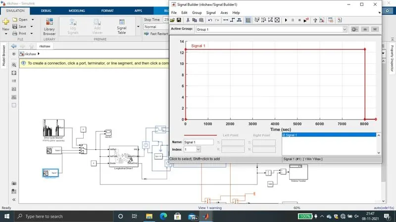
- A signal builder block is used for other 2 inputs as requested.
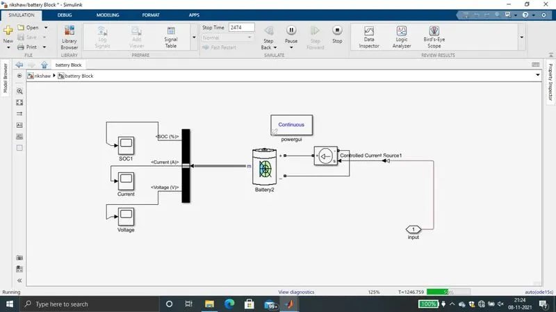
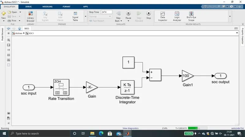
- Since we have using internal power supply in H bridge for calculating the state of charge a replica of internal power supply is built. This consists of a battery along with a controlled current source. the battery parameters add set asper our requirements like voltage and AH. Controlled current source input here is given from the current sensor we have described earlier (connected to measure current drawn by motor). We are using a state of charge block to determine amount of charging drained.
- here the lithium ion battery choosen also has inbuilt SOC indicator. That one can also be choosen to indicate battery charge percentage.
Results:
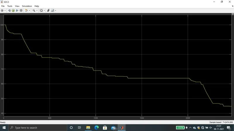
I have run the model using drive cycle FTP 75 war 2474 seconds in the results window it can be clearly seen that the vehicle is almost following the given drive cycle in battery state of charge scope also we can see the battery level. in this graph we can also observe that battery is charged during regenerative breaking. screenshots of the output and the model or attached.
Detailed Explaination:
- Here for this model the results can be viewed in two ways. First by comparing the given drive cycle with the actual output. That is we have connected the input drive cycle to the scope and the actual speed of the vehicle (this is obtained from vehicle body block).
- As you can see from the scope screenshot our model is following the input drive cycle to the most of the time. Perfect match can also be obtained by adjusting PI controller and motor gearbox ratio etc. Our vehicle deceleration time is more, this is the reason our vehicle is catching next speed before actually becoming zero, it is catching he drive cycle input at different speeds. This also so can be adjusted by changing the entire vehicle inertia.
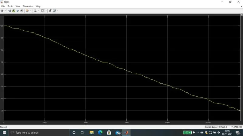
- The second one that can be evaluated is scope that is connected to state of charge of the battery. From this we can observe the amount of power consumed by the vehicle for the entire drive cycle.
- Here in this model we have considered a multi port switch on the input side. By this switch we can select vehicle ref speed vs time inputs. Here I have given three vehicle ref speed vs time options and either one can be selected. Model attached.
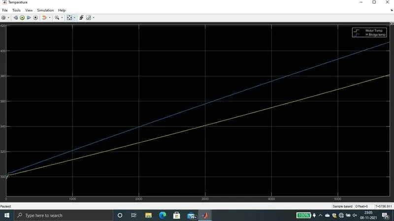
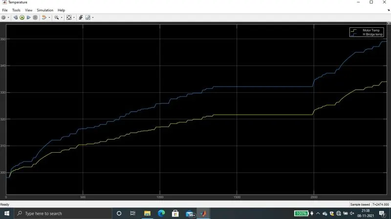
- H bridge controller and motor temperatures are also measured and they becaume constant at 350K
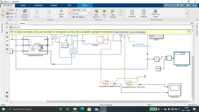
Run the model for 2nd drive ccle created using signal builder block for 200 sec and screen shots of results attached
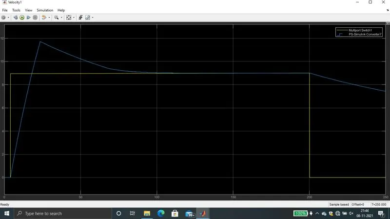
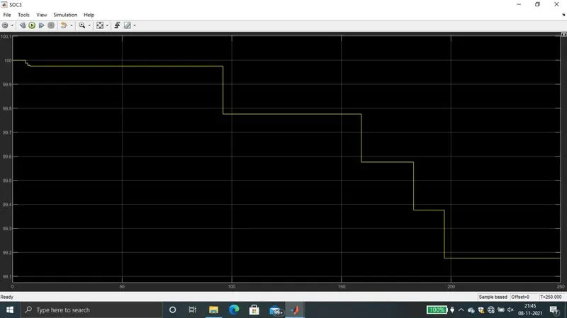
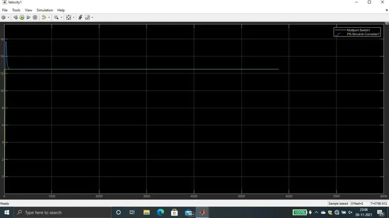
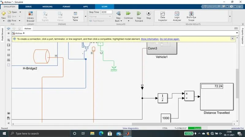
Run the model for 3rd drive cycle created using signal builder block which is 45kmph(12.5m/s for 8000 sec of simulation will give 100km travel.
As simulation is taking more time it is paused at 72% and screen sghots attached