Final Project: Design of an Electric Vehicle
AIM :-
Create a MATLAB model of electric car which uses a battery and a DC motor. Choose suitable blocks from Powertrain block set. Prepare a report about your model including following:
Objectives:
1. System level configurations
2. Model parameters
3. Results
4. Conclusion
Electrical vehicle :-
electric vehicle (EV) is a vehicle that uses one or more electric motors or traction motors for propulsion. An electric vehicle may be powered through a collector system by electricity from off-vehicle sources, or may be self-contained with a battery, solar panels, fuel cells or an electric generator to convert fuel to electricity.EVs include, but are not limited to, road and rail vehicles, surface and underwater vessels, electric aircraft and electric spacecraft.
EVs first came into existence in the mid-19th century, when electricity was among the preferred methods for motor vehicle propulsion, providing a level of comfort and ease of operation that could not be achieved by the gasoline cars of the time. Modern internal combustion engines have been the dominant propulsion method for motor vehicles for almost 100 years, but electric power has remained commonplace in other vehicle types, such as trains and smaller vehicles of all types.
Commonly, the term EV is used to refer to an electric car. In the 21st century, EVs have seen a resurgence due to technological developments, and an increased focus on renewable energy and the potential reduction of transportation's impact on climate change and other environmental issues. Project Drawdown describes electric vehicles as one of the 100 best contemporary solutions for addressing climate change.
Government incentives to increase adoption were first introduced in the late 2000s, including in the United States and the European Union, leading to a growing market for the vehicles in the 2010s.Increasing public interest and awareness and structural incentives, such as those being built into the green recovery from the COVID-19 pandemic, is expected to greatly increase the electric vehicle market. A pre-COVID 2019 analysis projected that Electric vehicles are expected to increase from 2% of global share in 2016 to 22% in 2030. Much of this market growth is expected in markets like North America and Europe; a 2020 literature review suggested that growth in use of electric vehicles, especially electric personal vehicles, currently appears economically unlikely in developing economies.
Electric Motor :-
The power of a vehicle's electric motor, as in other vehicles, is measured in kilowatts (kW). 100 kW is roughly equal to 134 horsepower, but electric motors can deliver their maximum torque over a wide RPM range. This means that the performance of a vehicle with a 100 kW electric motor exceeds that of a vehicle with a 100 kW internal combustion engine, which can only deliver its maximum torque within a limited range of engine speed.
Energy is lost during the process of converting the electrical energy to mechanical energy. Approximately 90% of the energy from the battery is converted to mechanical energy, the losses being in the motor and drivetrain.
Usually, direct current (DC) electricity is fed into a DC/AC inverter where it is converted to alternating current (AC) electricity and this AC electricity is connected to a 3-phase AC motor.
For electric trains, forklift trucks, and some electric cars, DC motors are often used. In some cases, universal motors are used, and then AC or DC may be employed. In recent production vehicles, various motor types have been implemented; for instance, induction motors within Tesla Motor vehicles and permanent magnet machines in the Nissan Leaf and Chevrolet Bolt.
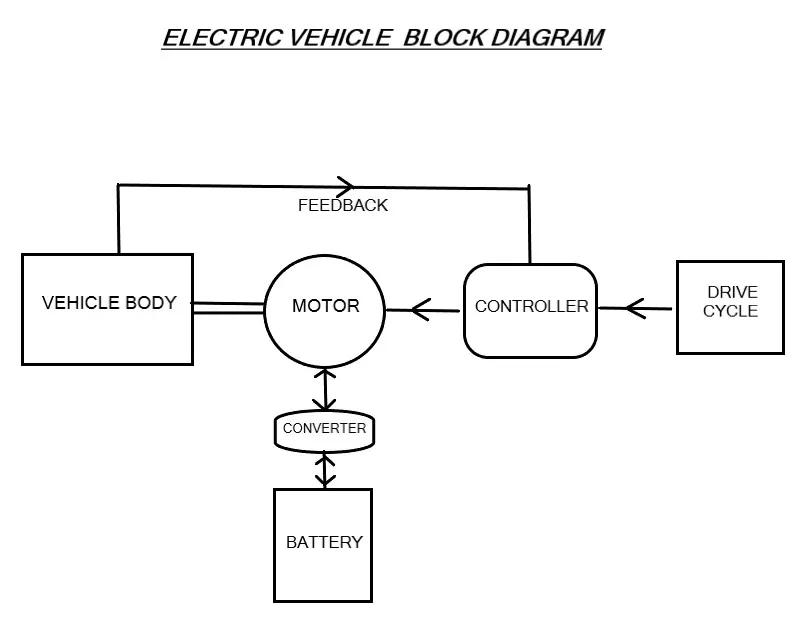
Block Diagram for design a model :-
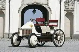
In 1880 Trouvé improved the efficiency of a small electric motor developed by Siemens (from a design purchased from Johann Kravogl [de] in 1867) and using the recently developed rechargeable battery, fitted it to an English James Starley tricycle, so inventing the world's first electric vehicle
Objectives :-
Develope simple electric vehicle model by usign dc motor and battery and observe system level configuration and model parameters
Model parameter :-
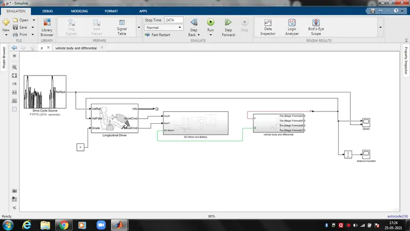
I develope simple model of electric vehicle model and i explain step by step below about model
SubSystems :-
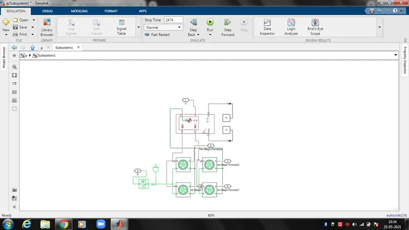
1. first we need to fix the vehicle body block first its represents vehicle dynamics
2. then used tire(magnetic formula) block and simple gear block to create base of our model, the tire block create four tyre for front and rear position
3. intertia block represents an ideal mechanical rotational inertia.The block has one mechanical rotational conserving port. The block positive direction is from its port to the reference point. This means that the inertia torque is positive if the inertia is accelerated in the positive direction
4. Here we observe various parameters in tyre,vehicle body,gear and inertia we can edit depends upon requirements
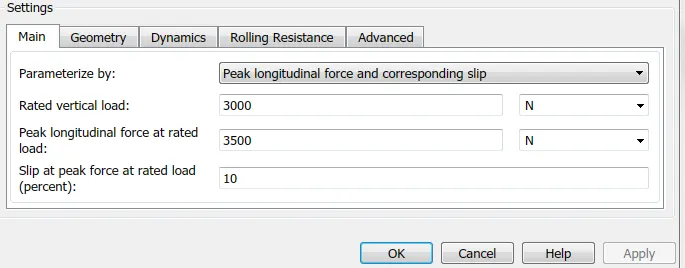
5.Ports of tire are connected with each other, A represents axile of vehicle, the rear and front axile wheel ports are connected each other
6. H is the hub is the mechanical translational conserving port associated with the horizontal motion of the vehicle body. The resulting traction motion developed by tires should be connected to this port, all h ports are connected each other.
7.port N is a physical signal input port that applies the normal force acting on the tire. The force is considered positive if it acts downwards, port S is a physical signal output port that reports the tire slip.
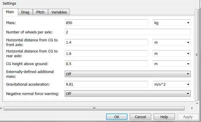
8.Port of vehicle body V, NF, and NR are physical signal output ports for vehicle velocity and front and rear normal wheel forces, respectively. Wheel forces are considered positive if acting downwards.
9.Port W and beta are physical signal input ports corresponding to headwind speed and road inclination angle, respectively.
10.If variable mass is modeled, the physical signal input ports CG and M are exposed,If both variable mass and pitch dynamics are included, the physical signal port J accepts the inertia of the additional mass about its own CG.
11.ports of gear ratio S and O are mechanical rotational conserving ports associated with the box input and output shaft, respectively. The gear ratio is determined as the ratio of the input shaft angular velocity to that of the output shaft.
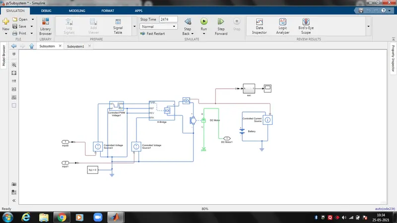
12.Simple battery is used for operation, connected with controlled current source.
13. DC motor block When a positive current flows from the electrical + to - ports, a positive torque acts from the mechanical C to R ports.
14. the output port of R is connected as input for gear box
15.Motor torque direction can be changed by altering the sign of the back-emf or torque constants, the positive and negative ports are connected to H bridge
16. To create PVM signal for H-block use Control PVM voltage block, the block generates the PVM signal which are generated according to the variable voltages.
17. The PVM and REF blocks are connected to PVM and REF of the h-bridge block, The ref port of PVM and H bridge is connected to electrical reference block
18. The control voltage source block represents an ideal voltage source that is powerful enough to maintain the specified voltage at its output regardless of the current passing through it.
19. The output voltage is V = Vs, where Vs is the numerical value presented at the physical signal port,
20. the input port of 0 and 1 is connected with control voltage source for accleration and de accleration.
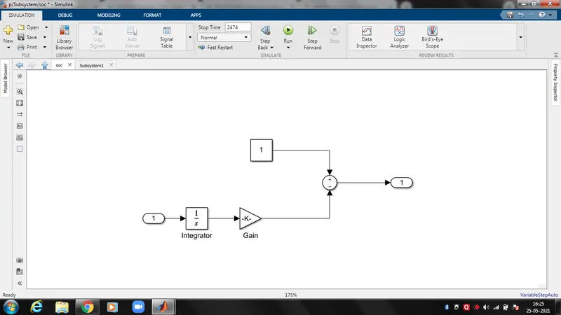
21. For calulate SOC we have generate another sub system,
22. The subsystem we can see that current from the controlled current source and current sensor is taken as input and connected to that, the gain block is order to update the voltage and time for one hour to solve
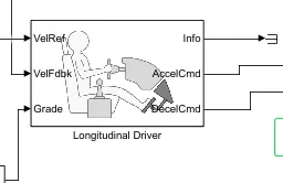
23. The longitudinal driver block is connected to standard drive cycle block for calclulate FTP75 drive cycle
24. parametric longitudinal speed tracking controller for generating normalized acceleration and braking commands based on reference and feedback velocities.
25. Use the external actions to input signals that can disable, hold, or override the closed-loop commands determined by the block. The block uses this priority for the input commands: disable, hold, override.
26. The velocity reference port is connected to the drive cycle and velocity feed back is connected to the scope
27. the grade port we fix the constant block as 0 and teminator is used to terminate the output signals
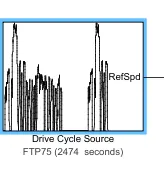
28. Drive cycle Generates a standard or user-specified longitudinal drive cycle. The block output is the vehicle longitudinal speed.
29. Use the fault tracking parameters to identify drive cycle faults within specified speed and time tolerances
30. We fix the output velocity units as m/s in drive cycle block and follow the same as all unit ports and blocks.
Result :-
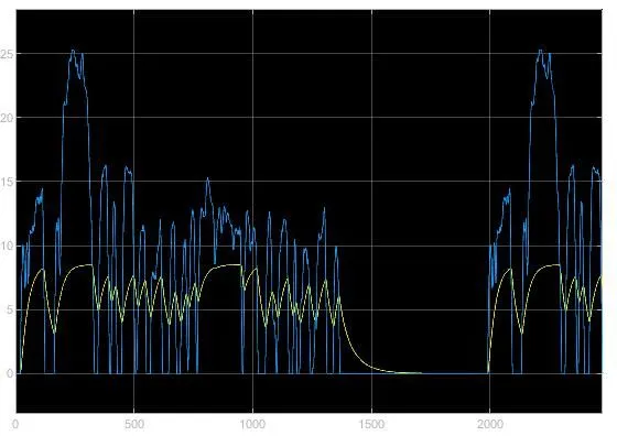
From above graph we oberve that vehicle speed is smilar to the drive cycle speed
Now need to the change the model parameter to get speed range is close to drive cycle range
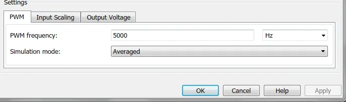
change DC motor parameter 50KW to 500KW and Pulse width modulator frequency changes to 1000 to 5000hz
then the result is
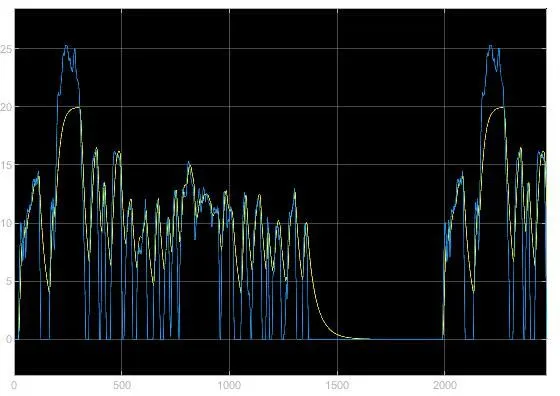
This graph shows the velocity is near to the drive cycle speed and so the electric vehicle meets the necessary speed
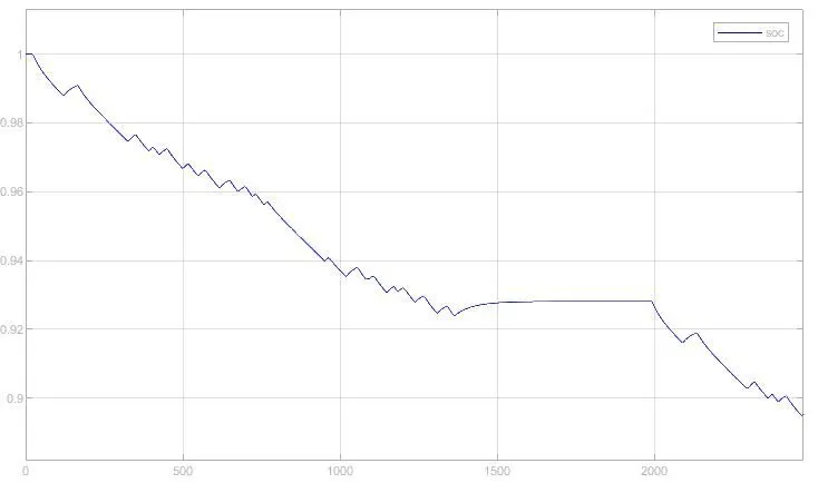
SOC graph shows the battery is less compared to the start at the drive end it shows the power of the battery is used so its need to charge but charging is less then the rate of discharging
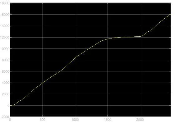
Above graph shows the distance is increasing that represents the vehicle is moving in positive direction
Conclusion :-
1.Electric vehicle model was modelled sucessfully
2.Further improvise the parameter to get better results
3.Plot the graph and compare the results of drive cyle speed and velocity speed
4.Google drive link for the model :-https://drive.google.com/file/d/1ePo5dT7HSo9dlIjGhiVq7GUH8O7IC6LW/view?usp=sharing