Final Project: Design of an Electric Vehicle
The modelling of an electric vehicle with a DC motor and battery system using the SIMULINK software is as shown below. The components in the model are the existing blocks in the SIMULINK block library. This EV model gives the result for the drive cycle given as the input to the model and measure the velocity characteristics and the current and SOC characteristics of its battery system.
The simulink EV model is as follows:
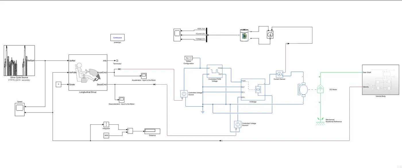
The detailed analysis of the model created is as follows:
To create a model of electric car which uses a battery and a DC motor requires the following major components.
Vehicle body:
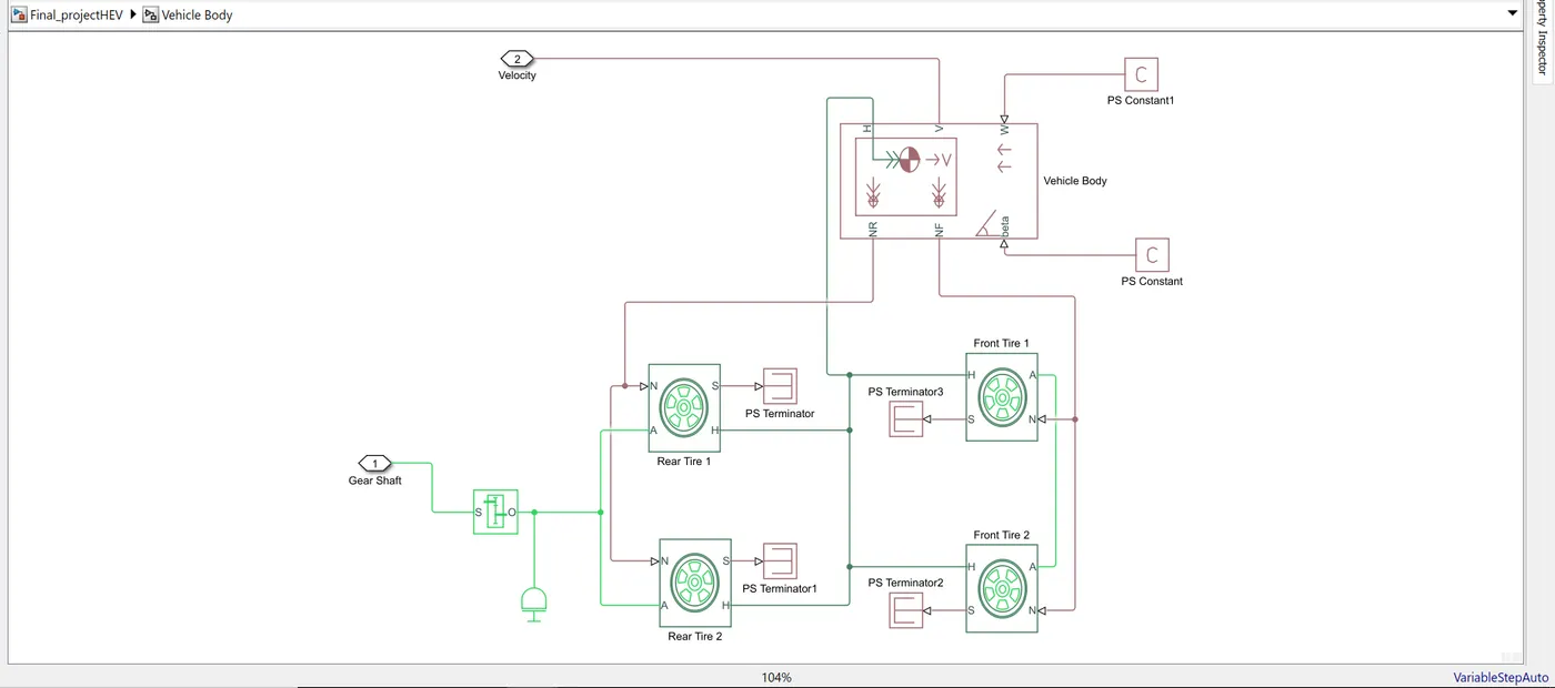
The Vehicle Body block represents a two-axle vehicle body in longitudinal motion. The vehicle can have the same or a different number of wheels on each axle. The block consists of body mass, aerodynamic drag, road incline, and weight distribution between axles due to acceleration and road profile. In optionally we can include pitch and suspension dynamics.
The block has an option to include an externally-defined mass and externally-defined inertia. The mass, inertia, and centre of gravity of the vehicle body can vary over the course of simulation in response to system changes.
In a given block
- NR: It is a physical signal output which is connected to the rear wheel axel. For this model, it is connected with a normal force of rear tire.
- NF: It is a physical signal output which is connected to front-wheel axel and for this particular model it is connected with the normal force acting on a front-wheel tire.
- Beta: Beta is basically a road incline angle. Here we can define a constant value for road angle inclination.
- H: This port is a horizontal motion of the vehicle body. This connection will be connected with all four Hub of the wheel for finding the thrust generated by the tire.
- V: This port is the vehicle longitudinal velocity.
- W: It is a headwind speed. Basically, we will define a particular wind speed by adding constant block.
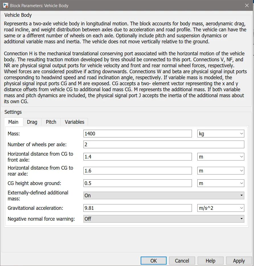
The vehicle body block parameters considered is as follows:
The Tire (Magic Formula) block models the tire as a rigid wheel-tire combination in contact with the road and subject to slip. When torque is applied to the wheel axle, the tire pushes on the ground (while subject to contact friction) and transfers the resulting reaction as a force back on the wheel. This action pushes the wheel forward or backwards. As shown in the below simulink the rear and front tires are connected where
- N: Normal force acting on the tire and connected with NR of the vehicle body.
- S: Slip between the tire and road and connected with PS terminator block.
- H: Hub and it is used to find the thrust created by the tire and it is connected with H input of vehicle body also including all four Hub of the wheel.
- A: Axel and rear axle are connected with the (Simple Gear) final drive system and the front axle is connected with the left and right wheel.
Inertia block generally represents the mechanical rotational element.
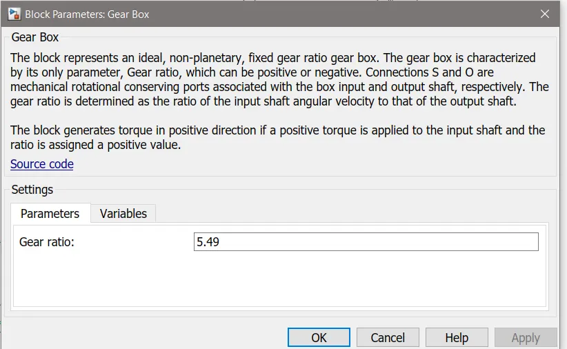
Gear Box is connected to the DC motor(R).
DC Motor:
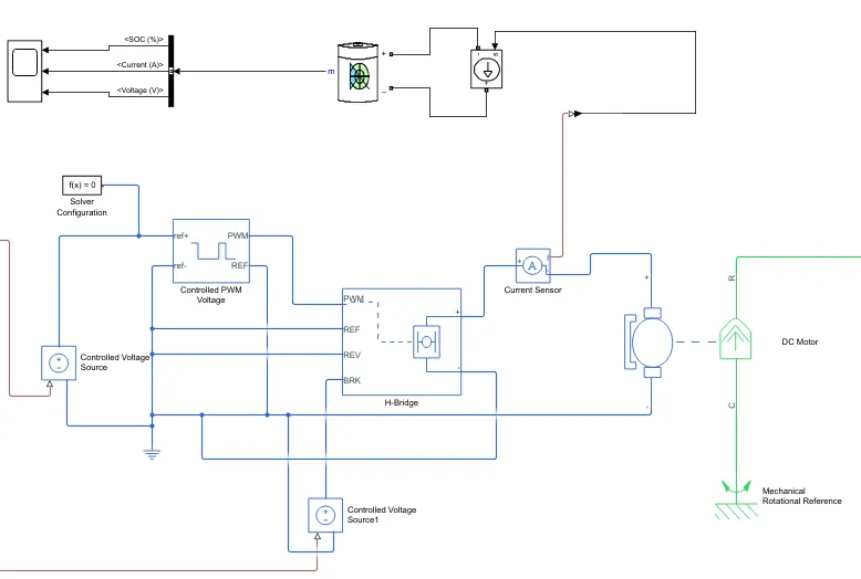
The DC Motor block represents the electrical and torque characteristics of a DC motor. Here in this system, the positive terminal is connected with the current sensor negative terminal and negative terminal is connected with the negative terminal of H-Bridge.
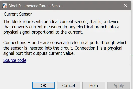
The current sensor block represents an ideal current sensor and is used to convert the current measured in an electrical circuit to a physical signal that is proportional to the current. This block is used to measure the current between the battery circuit (controlled current source) and the DC motor.
R is DC motor rotor which connected with mechanical rotational port i.e. simple gear whereas C is DC motor case and it is connected with mechanical rotational reference.
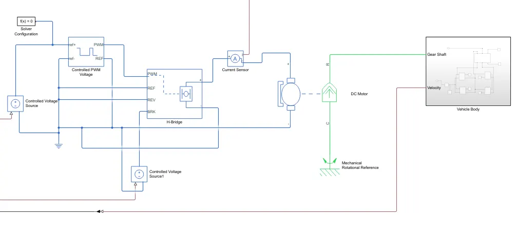
As we can see, there are 2 sides to the block: the mechanical side on the right and the electrical side on the left. The mechanical side has 2 ports, C and R. The C refers to the casing and the R for the rotation of the rotor which produces a torque. The electrical side has a positive and a negative terminal for the voltages to be applied. If a positive voltage is applied to the DC motor block from the positive to the negative terminal, a positive torque will act from the C port to the R port. The direction of the torque produced by the DC motor can be changed by changing the sign of the back emf or the torque constant. The C port of the mechanical side needs to be connected to a mechanical rotational reference because it will be stationary. The R port will be connected to the open connection of the simple gear from the vehicle body block. The positive terminal on the electrical side is connected to the positive terminal of H- bridge power converter.
A basic configuration of the DC motor is as follows:
H- Bridge:
The power converter is needed to provide power of the correct form and magnitude from one component to another. In the case of EVs, a power converter is needed to provide a DC voltage from the battery of the EV to the DC motor so that it can operate properly with the required parameters. The H-Bridge motor drive is used as the power converter. Its block is shown below:
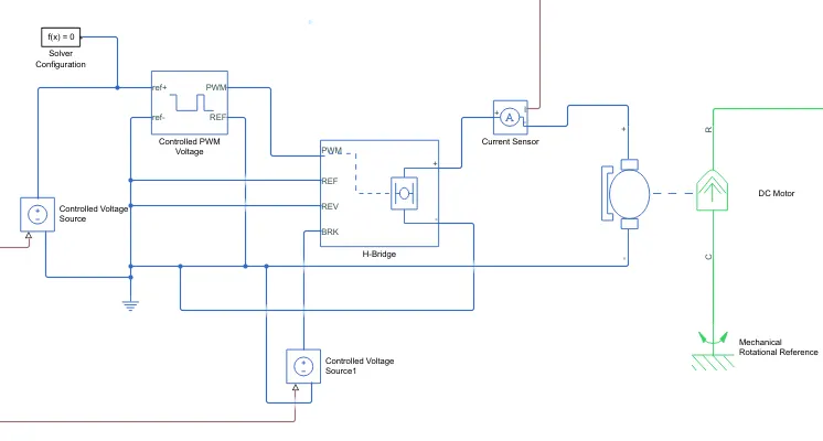
The H Bridge has 2 sides to it: the left side is for the controlling of the voltage signals and the right side is for the terminals to provide the controlled voltage to the DC motor. The left side ports of the H-Bridge block are:
- PWM - This stands for Pulse Width Modulation which will provide the voltage pulses to the H-Bridge either in the PWM or average mode.
- REF - This stands for Reference.
- REV - This stands for Reverse.
- BRK - This stands for Brake.
The H-bridge parameters considered is as follows:
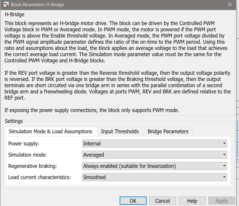
The H-Bridge to run on an internal power supply with an averaged simulation mode instead of the PWM mode is selected. This is because using the PWM mode will result in significantly longer simulation times compared to using the averaged mode.
Controlled PWM voltage:
Controlled PWM Voltage block is used to provide a controlled pulse width modulated voltage to the H-Bridge block. The block will output the PWM voltage through its 'PWM' and 'REF' ports which will feed in to the same ports found on the H-Bridge block. If the pulse is low the output voltage is considered 0V whereas if the pulse is high, the output voltage will be equal to the output voltage amplitude. The pulses of voltage created by this block are dependent on the duty cycle which is the ratio of the time that the switch is ON to the time taken for 1 cycle (which is the time for which the switch is ON and OFF). The duty cycle is set by the input of the controlled PWM voltage block.
The Controlled Voltage Source block represents an ideal voltage source that is powerful enough to maintain the specified voltage at its output regardless of the current flowing through the source. The block has one physical signal input port and two electrical conserving ports associated with its electrical terminals.
Solver configuration is used to begin the simulation and it is needed to solve the Simulink model. Here it is connected with controlled PWM voltage and H-Bridge negative connection by combination with electrical reference i.e ground signal.The configuration parameters is as follows:
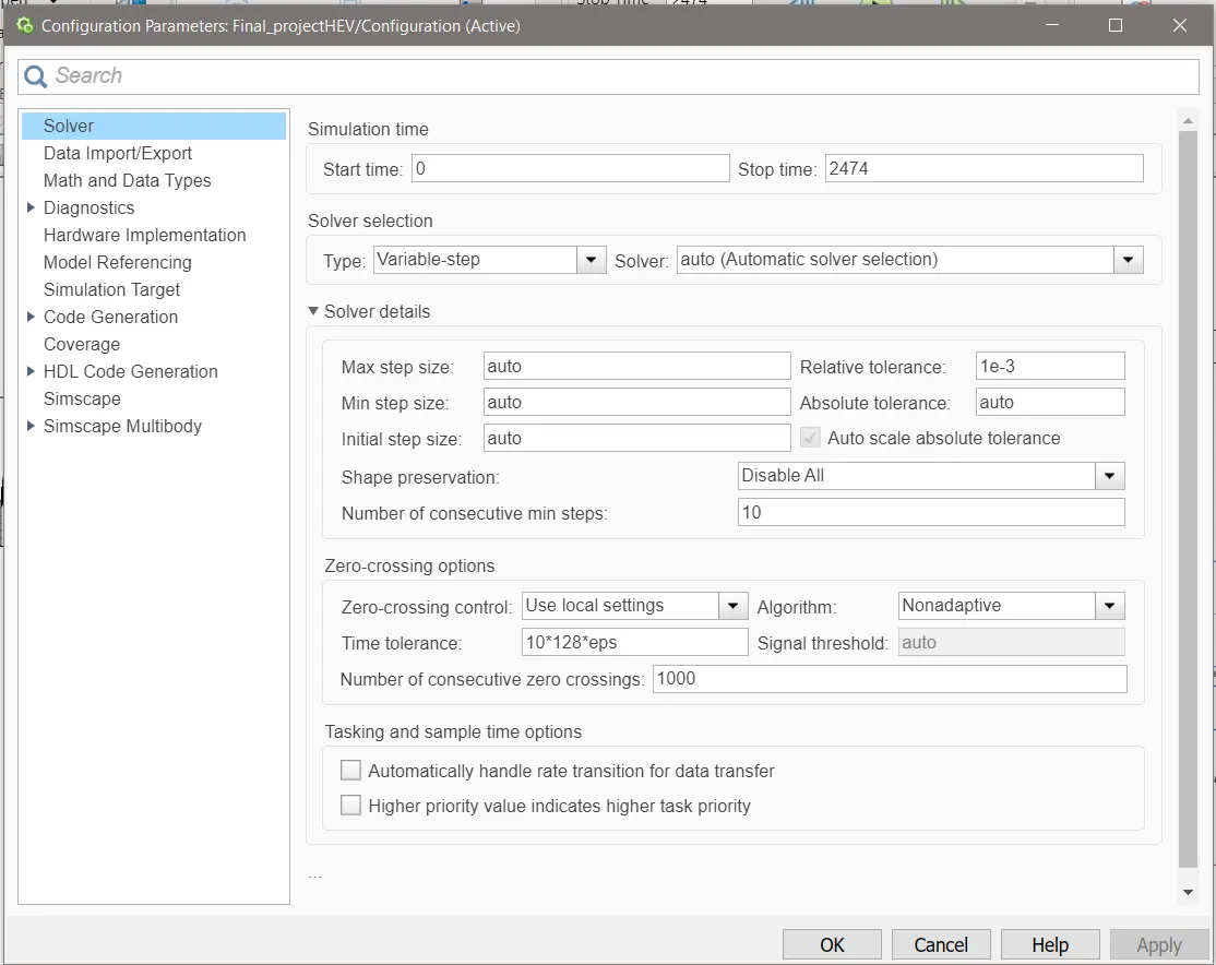
The electrical reference block is used to create a grounding effect for electrical circuits. Any model that uses electrical or electronics components will need to have at least one electrical reference block in it. In this EV model, the electrical reference is used to create an electrical ground between the controlled voltage source, controlled PWM voltage and the H-Bridge blocks
Battery system:
The battery will be the energy store of the EV and will contain the electrical energy in DC form and provide this energy to the DC motor for it to operate. The battery block used is a simple one and considers only the basic parameters. The battery block is shown below:
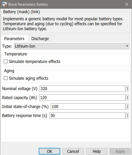
The lithium - ion battery parameters considered is as follows:
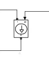
The Controlled Current Source block represents an ideal current source that is powerful enough to maintain the specified current through it regardless of the voltage across the source. In this particular block, the two-port is connected with battery and one electrical conversing port is connected with PS-Simulink converter to the rate transition block and Scope block.
The PS-Simulink Converter block converts a physical signal into a Simulink output signal. This block is used to connect outputs of a Physical Network diagram to Simulink scopes or other Simulink blocks.
Longitudinal Driver:
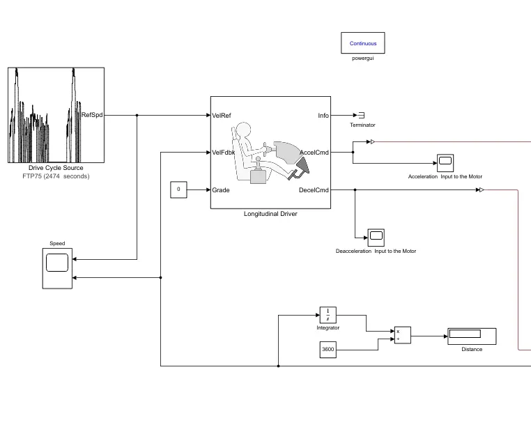
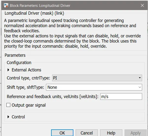
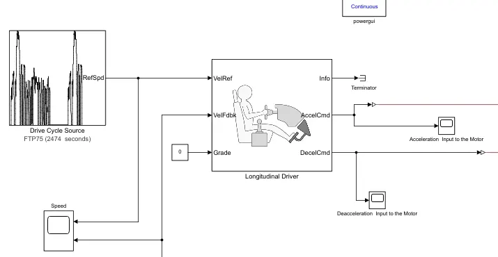
The Longitudinal Driver block implements a longitudinal speed-tracking controller as shown below. The control used here is PI which is a Proportional-integral (PI) control with tracking windup and feed-forward gains.
The block parameters are as follows:
The longitudinal driver block has the following ports:
- VelRef - This stands for the reference velocity and it is the velocity data provided from a drive cycle source.
- VelFdbk - This stands for the feedback velocity and it is the velocity data provided from the vehicle body's velocity port which outputs the velocity data.
- Grade - This port provides a grade or inclination angle for the surface on which the vehicle is travelling in degrees.
- Info - This port is for the bus signals which consist of block calculations e.g. acceleration/deceleration command, difference between reference and vehicle speed.
- AccelCmd - This port provides the acceleration command to a controlled voltage source.
- DecelCmd - This port provides the deceleration command to another controlled voltage source.
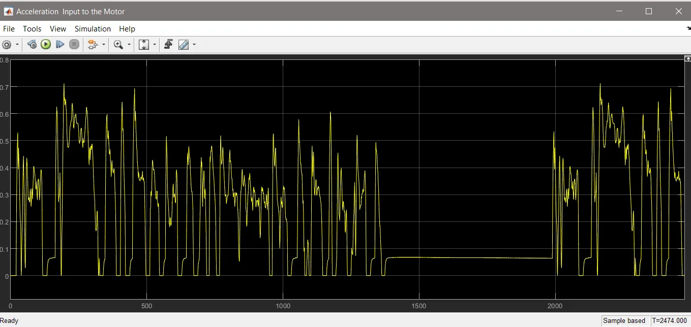
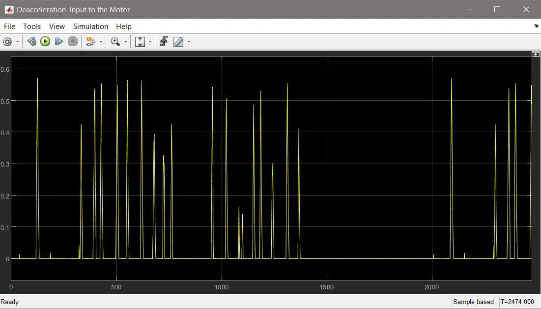
The working of the longitudinal driver block is simple. The reference velocity data coming from a drive cycle source is compared to the feedback velocity data coming from the vehicle body block. If the reference velocity is greater than the feedback velocity, an acceleration command will be given as an output to the controlled voltage source. If the reference velocity is lesser than the feedback velocity, a deceleration command is given as the output to another controlled voltage source instead. For the acceleration and deceleration commands to be given as output signals, the Simulink - PS converter block is used. This block is needed whenever we wish to connect a Simulink input signal to a physical signal. In this case, the input signal is velocity data and this is logic data which we want to convert to a physical signal i.e.. voltages to the controlled voltage source.
The grade port of the longitudinal driver block is connected to a constant block with a constant value of 0. This is so that no road inclination is modelled for the simulation.
Drive cycle :
A drive cycle is a data set that contains velocity and time data for the purpose of modelling the motion of a vehicle. The drive cycle will be a plot of the velocity against the time and it is made to resemble typical driving conditions that a consumer may experience themselves in. For instance, they can model highway driving situations, driving in urban areas, or driving with full power etc. Drive cycles are used by automotive companies for various testing procedures such as mileage, pollution tests, and acceleration and top speed tests. There are various different drive cycles that are industry standard e.g. Urban Dynamometer Driving Schedule (UDDS), FTP 75.
In this EV model, a drive cycle is used as the reference velocity data for the longitudinal driver block to send acceleration or deceleration commands according to the drive cycle. By default, the drive cycle block is set to the FTP75 drive cycle as shown below:
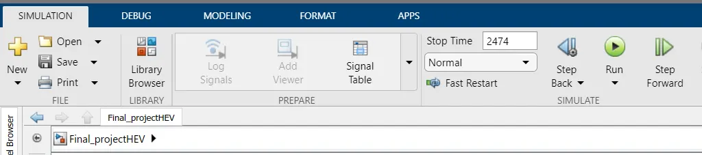
According to the drive cycle time the simulation time is updated as shown below:
Distance calculation:
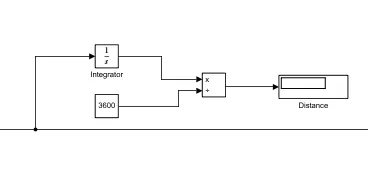
Here the main block is an integrator, Divide, time block and for the result we have to use display block that will display the distance.
Integrator : The output port of the vehicle body is connected with the integrator block.
Divide : The output of the integrator block is connected with divide where it will be divided by time to get the final output.
Time : The output of time block is connected with the divide block. Here time is taken as 3600 secs.
RESULT :
All the plots in x axis have time in seconds.
Speed of the vehicle and the drive cycle:
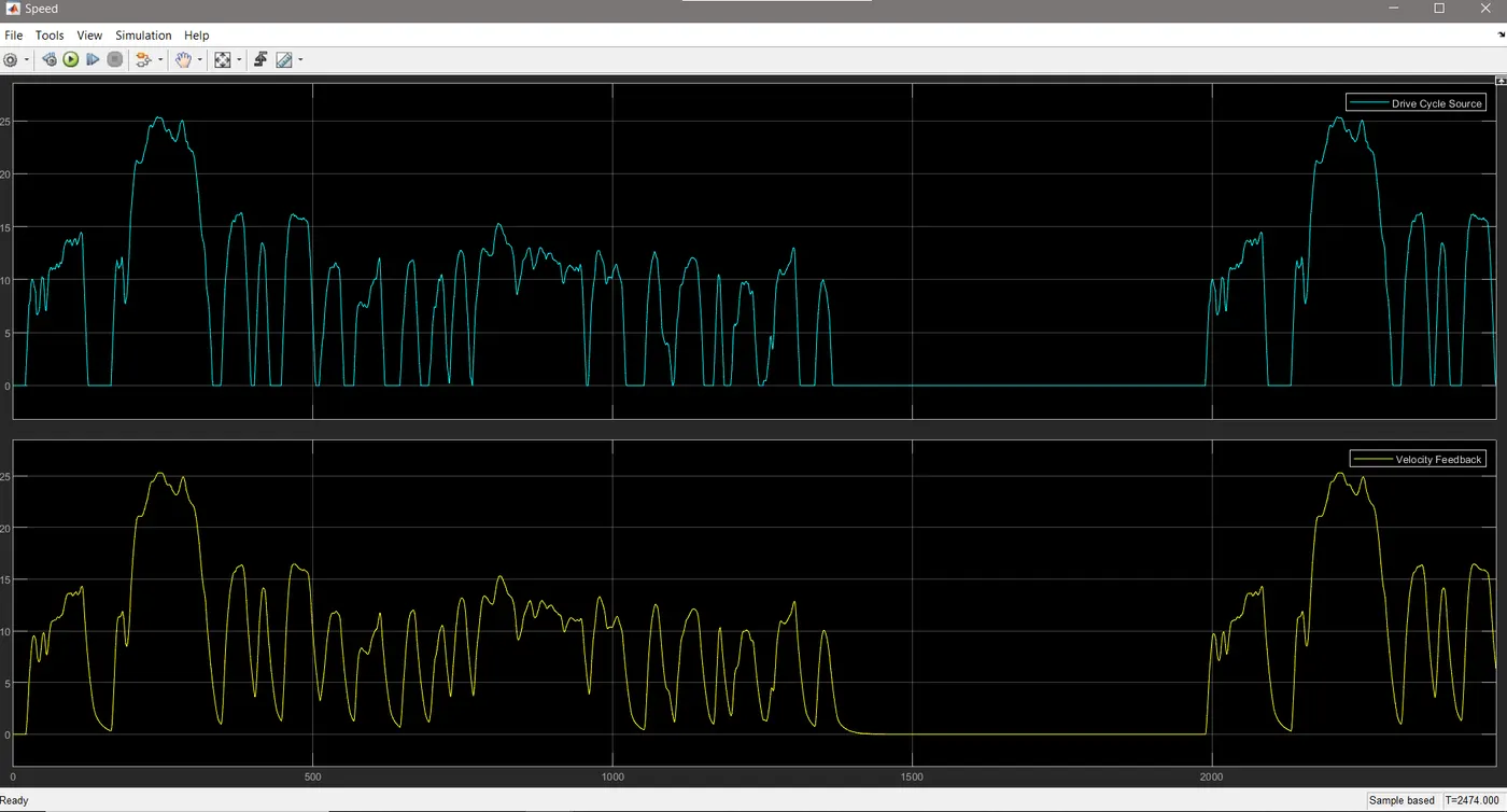
The blue signal represents the reference signal which originates from the drive cycle data whereas the yellow signal shows the actual velocity of the vehicle. The vehicle velocity has accelerated and decelerated as the drive cycle commanded.
Accelaration & Decelaration input to the motor:
Battery parameters:
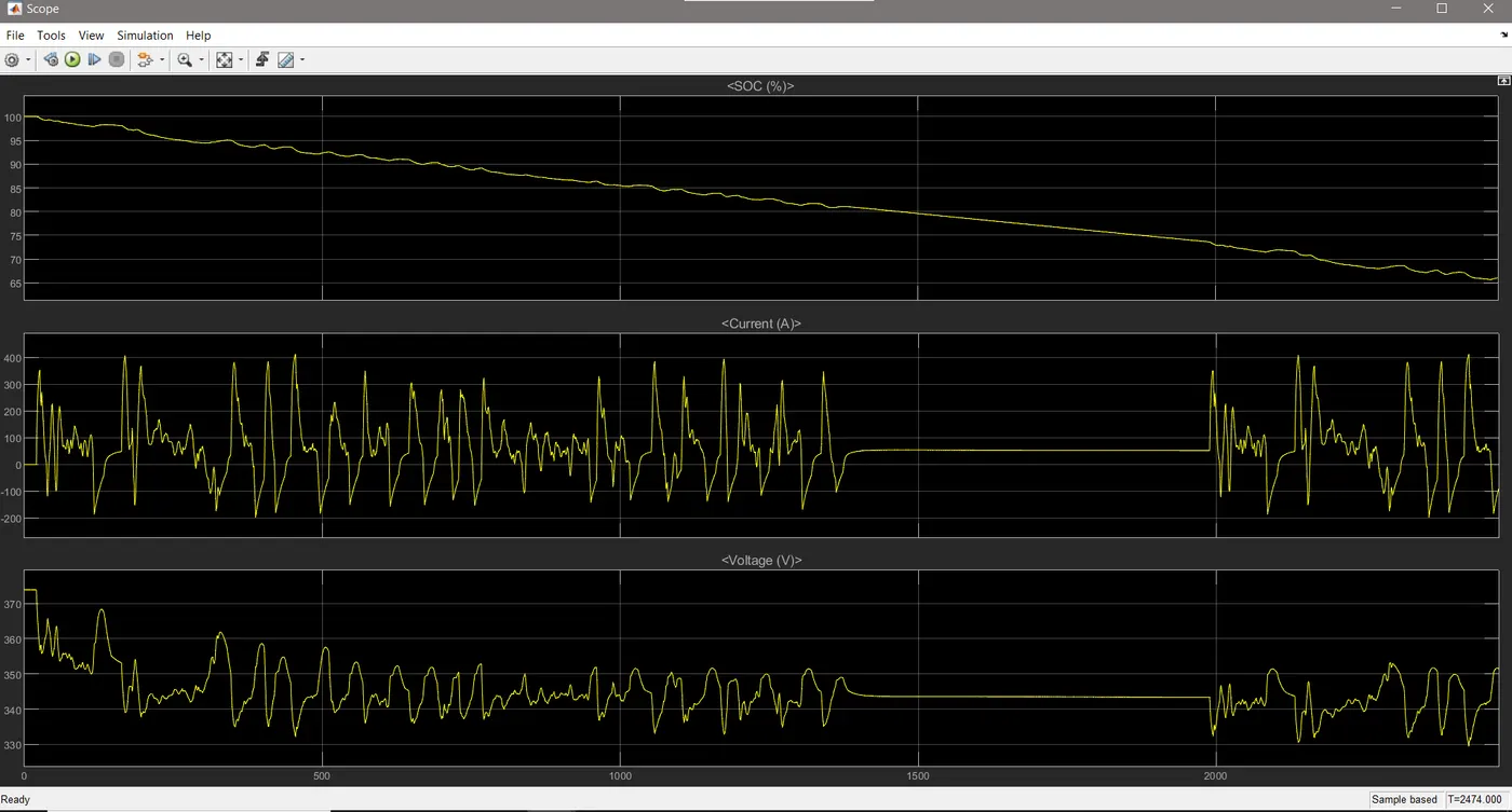
Conclusion:
The total distance travel by vehicle is 5.323 m/s depending upon the FTP75 drive cycle and the total time for simulation was 2474 sec.
The battery is having 320 V which is a nominal voltage and the battery ampere per hour rating is 120 by which we calculated the SOC (state of charge) of battery.
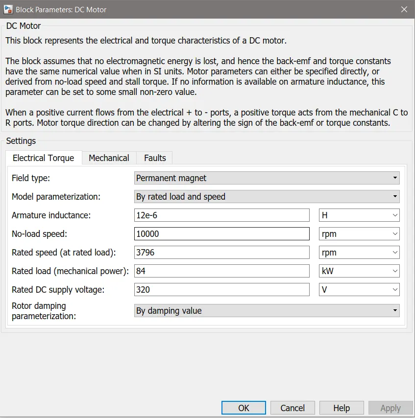
The DC motor is used to run the Rear axel of the vehicle and when the car is with no load condition then the motor operating RPM is 10000 and when the car is running at some load or we can say that some rated speed then the motor RPM is taken as 3796. The voltage supply to DC motor is 320 V.