Final Project: Design of an Electric Vehicle
AIM : To create a MATLAB model of electric car which uses a DC motor by choosing suitable blocks from Powertrain block set.
OBJECTIVES : To prepare a technical report about the EV model including -
- System level configurations
- Model parameters
- Results
- Conclusion
THEORY :
An Electric Vehicle (EV) is a vehicle that uses one or more electric motors or traction motors for propulsion. An electric vehicle may be powered through a collector system by electricity from off-vehicle sources, or may be self-contained with a battery, solar panels, fuel cells or an electric generator to convert fuel to electricity. EVs include, but are not limited to, road and rail vehicles, surface and underwater vessels, electric aircraft and electric spacecraft.
Components
The main components of modelling an EV are:
- Vehicle body
- Motor & motor controllers
- Power converters
- Batteries
- Drive cycle
- EVs have no need for the fuel engine and gear transmission, the two of the most crucial components for internal combustion vehicles.
- An electric powered car has three primary components - Battery, motor controller, and the electric motor.
(A) Battery : The battery of an electric car can be charged through the use of ordinary grid electricity at a specialized power station. But aside from the conventional lithium-ion battery technologies, there are also other major battery technologies which can be used for electric cars.
- Lithium-Ion Batteries : This battery technology gives extra performance and range. However, it also carries the highest price tag. Lithium-ion batteries are lighter than Lead acid and Nickel metal. These are also the batteries used in digital cameras and smartphones.
- Lead Acid Batteries : This battery technology is the most popular. It is also the cheapest among the battery technologies. What’s good about it is it’s 97% recyclable.
- Nickel Metal Hydride Batteries : This battery technology provides higher output and better performance but it costs much more than lead-acid batteries.
(B) Motor Controller : The motor controller of an electric car administers its complete operation and the distribution of its power at any given moment. It acts as a floodgate between the motor and batteries. It helps monitor and regulates all key performance indications such as the vehicle’s operator, motor, battery, and accelerator pedal. It has a microprocessor which can limit or redirect current. It is used to either improve the mechanical performance of the car or suit the operator’s driving style. There are also more refined controllers which are capable of greater accuracy and thus, higher efficiency.
(C) Electric Motor : Unlike a gasoline engine with lots of moving parts, a motor only has one moving part. This makes it a very reliable source of motive power. Choosing an electric motor depends on the car’s system voltage. They can be structured to use either AC or DC current. AC motors are less expensive and lighter compared to DC motors. They are also more common and they tend to suffer from less mechanical wear and tear. However, AC technology requires a more refined or sophisticated motor controller.
- System level configurations
The proposed configuration also suggests fast switching between the motoring and regenerative modes by enabling or disabling the gate pulses to the inverter or DC/DC boost converter. This removes the need for a separate switch in the power circuit, hence increasing reliability and reducing cost.
2. Model parameters-
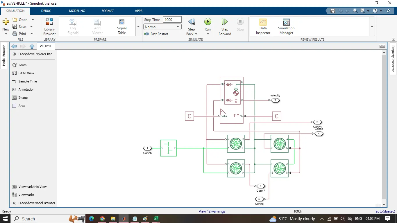
subsystem
parameter taken for vehicle body-
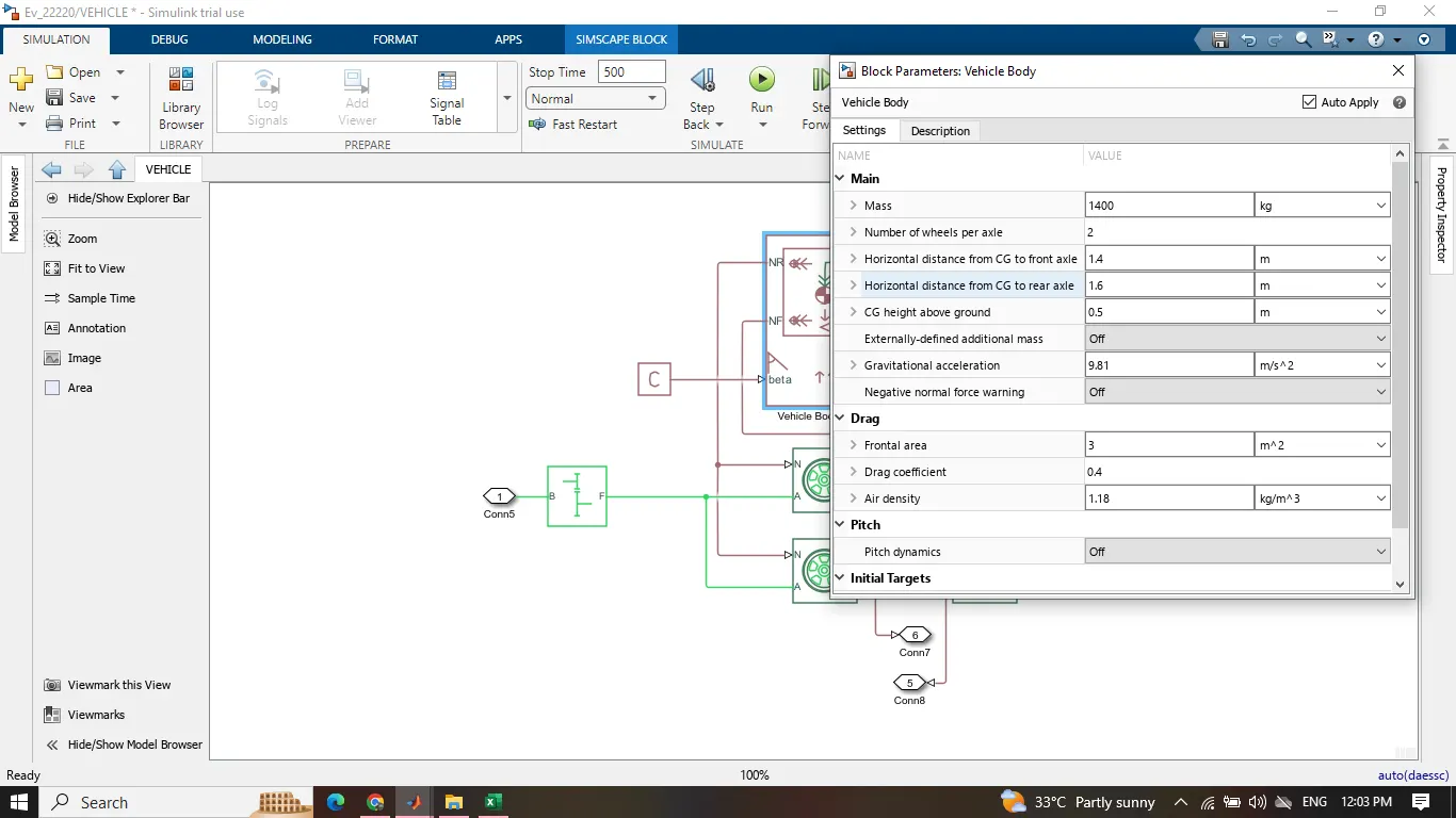
PROCESS -
1st a vehicle block has taken, there are six ports on a vehicle body named as NR,NF,beta,W,V,H, respectively. Connection H is the mechanical translational conserving port associated with the horizontal motion of the vehicle body. The resulting traction motion developed by tires should be connected to this port. Connections V, NF, and NR are physical signal output ports for vehicle velocity and front and rear normal wheel forces, respectively. Wheel forces are considered positive if acting downwards. Connections W and beta are physical signal input ports corresponding to headwind speed and road inclination angle, respectively.
Then taken 4 tires to make it four wheeler there are four ports in a tire i.e A,N,H,S, Connection A is the mechanical rotational conserving port for the wheel axle. further connected with the gear box of the vehicle.Connection H is the mechanical translational conserving port for the wheel hub through which the thrust developed by the tire is applied to the vehicle. Connection N is a physical signal input port that applies the normal force acting on the tire. The force is considered positive if it acts downwards. Connection S is a physical signal output port that reports the tire slip.
combine tires and vehicle body and a gear system makes a subsystem named as VEHICLE BODY,
and a DC motor connected along the vehicle body, DC motor parameter shown in the fig, below. there are 4 ports i.e +,-,C,R When a positive current flows from the electrical + to - ports, a positive torque acts from the mechanical C to R ports. Motor torque direction can be changed by altering the sign of the back-emf or torque constants.
The gear box terminal B is connected with the DC motor terminal R,and the C port connected with the mechanical reference. 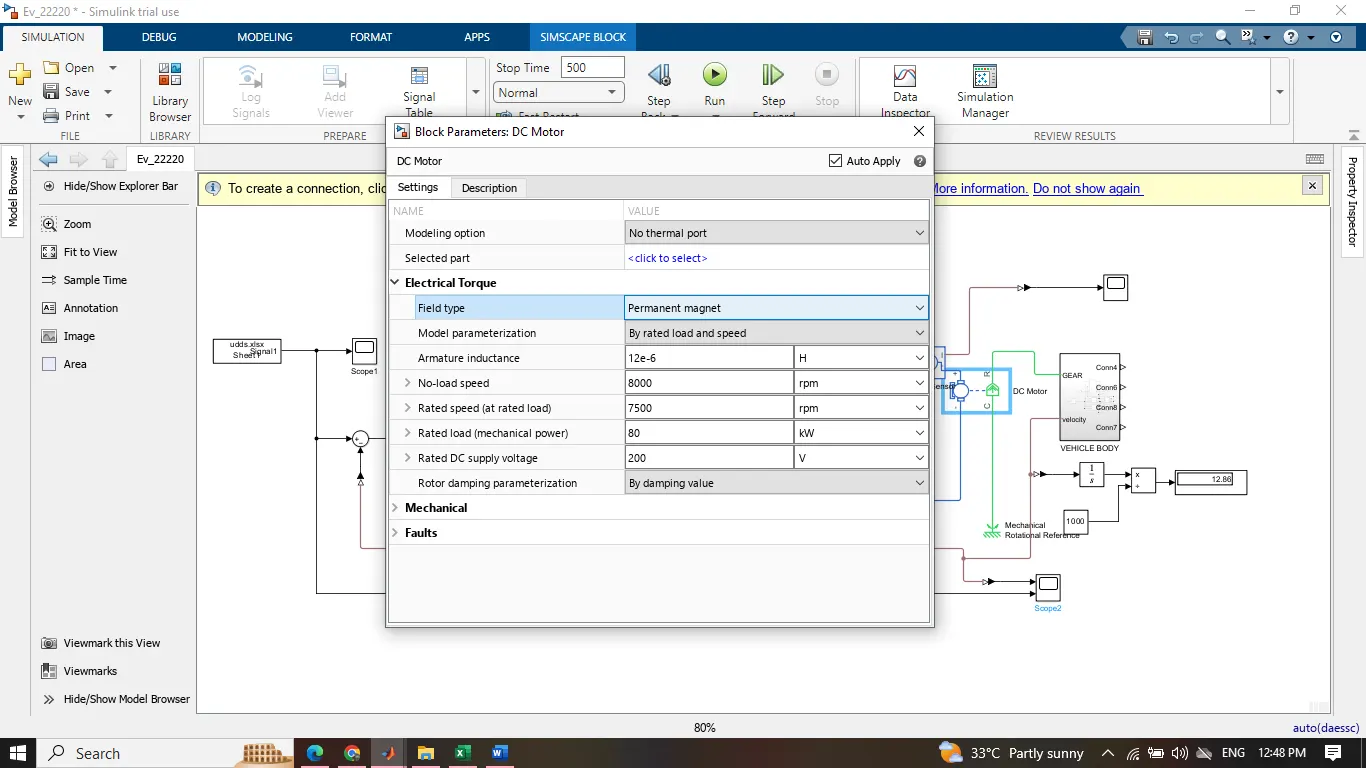
positive port of our dc motor connected with the negative port of the current sensor.
The next is the current sensor The block represents an ideal current sensor, that is, a device that converts current measured in any electrical branch into a physical signal proportional to the current. Connections + and - are conserving electrical ports through which the sensor is inserted into the circuit. Connection I is a physical signal port that outputs current value. the I port is connected further with the S port of the controlled current source.
Then taken a H-BRIDGE block This block represents an H-bridge motor drive. The block can be driven by the Controlled PWM Voltage block in PWM or Averaged mode. In PWM mode, the motor is powered if the PWM port voltage is above the Enable threshold voltage. In Averaged mode, the PWM port voltage divided by the PWM signal amplitude parameter defines the ratio of the on-time to the PWM period. Using this ratio and assumptions about the load, the block applies an average voltage to the load that achieves the correct average load current. The Simulation mode parameter value must be the same for the Controlled PWM Voltage and H-Bridge blocks.
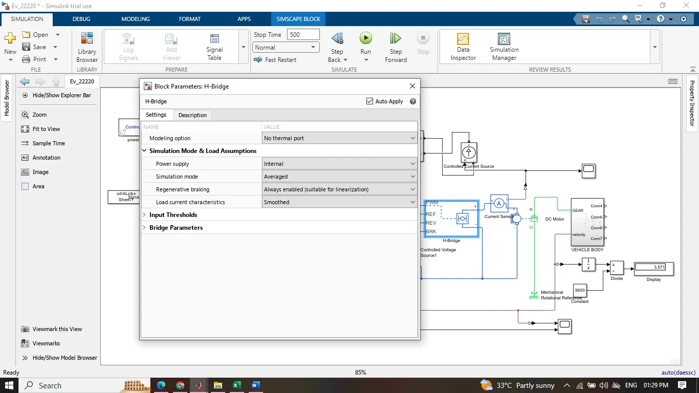 aand taken a controlled PWM voltage source to connect with the H-bridge.that block takes input from a controlled voltage source and that controlled voltage source block taken inputs from the PID controller which i used instead of the longitudenal driver . along with some saturation block or transfer function block PID block This block implements continuous- and discrete-time PID control algorithms and includes advanced features such as anti-windup, external reset, and signal tracking. You can tune the PID gains automatically using the 'Tune...' button (requires Simulink Control Design).
one controlled voltage block connect with the controlled pwm voltage source and one connect with the braking terminal of the h-bridge .and all the physical model - port are connected with a commen point as elelctrical refrence block.
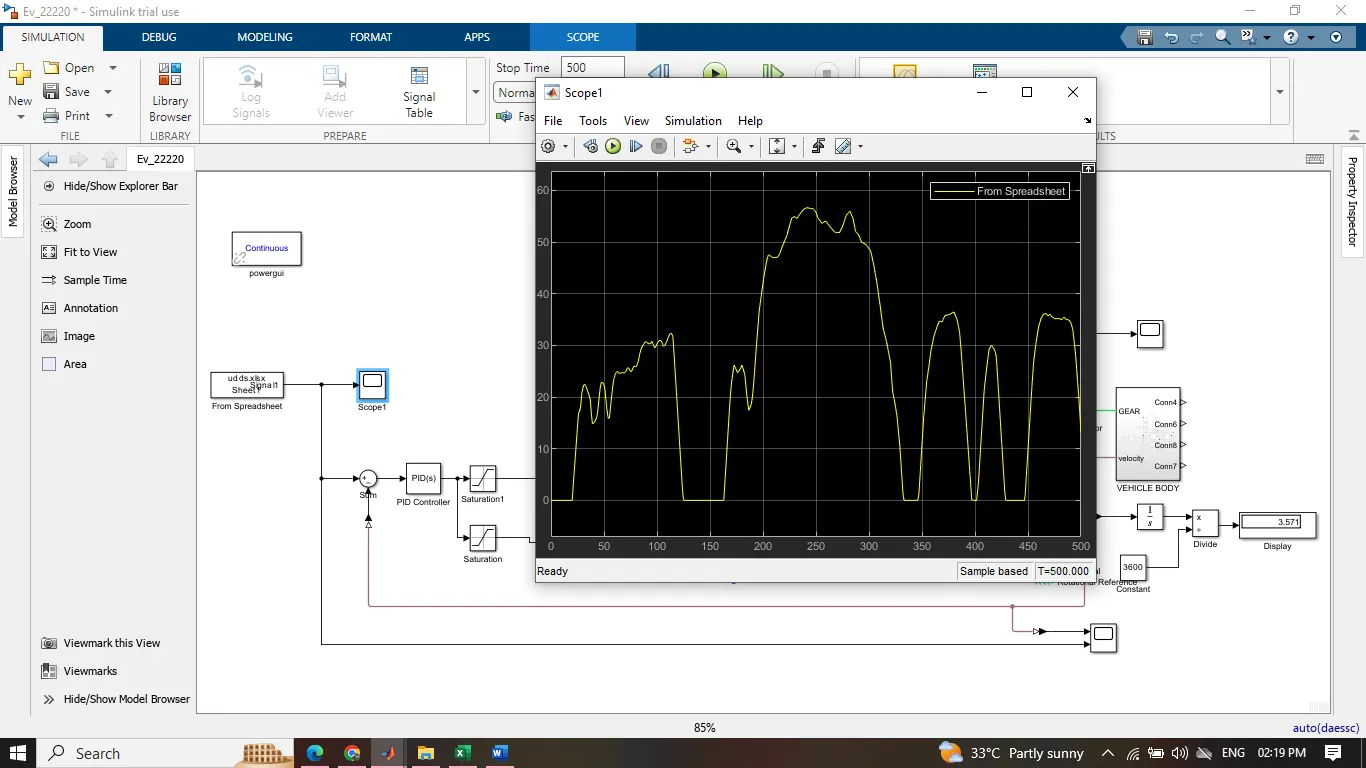
from the spread sheet i have choosen the UDDS driving cycle data for the model i.e The EPA Urban Dynamometer Driving Schedule (UDDS) is commonly called the "LA4" or "the city test" and represents city driving conditions. It is used for light duty vehicle testing. The UN/ECE Regulation 53 refers to the EPA UDDS as the "Test Equivalent to the Type 1 Test (verifying emissions after a cold start).
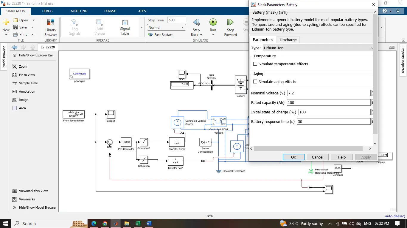
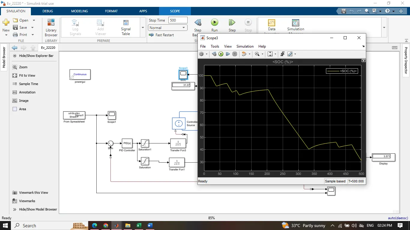
and a battery taken for the power supply a controlled current source connected with the batterry . and a bus bar is connected with the M terminal of the battery to check the soc at different different time duration.
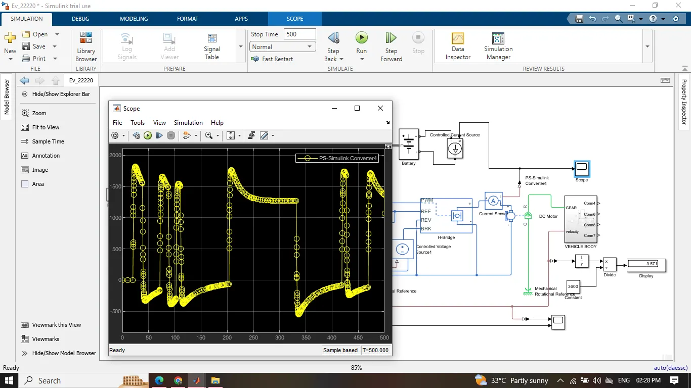 and use a sum block to take input from the spread sheet and the negative port taken the feedback i.e the velocity of the vehicle. and further scope and displays are taken for visulizing the performance.
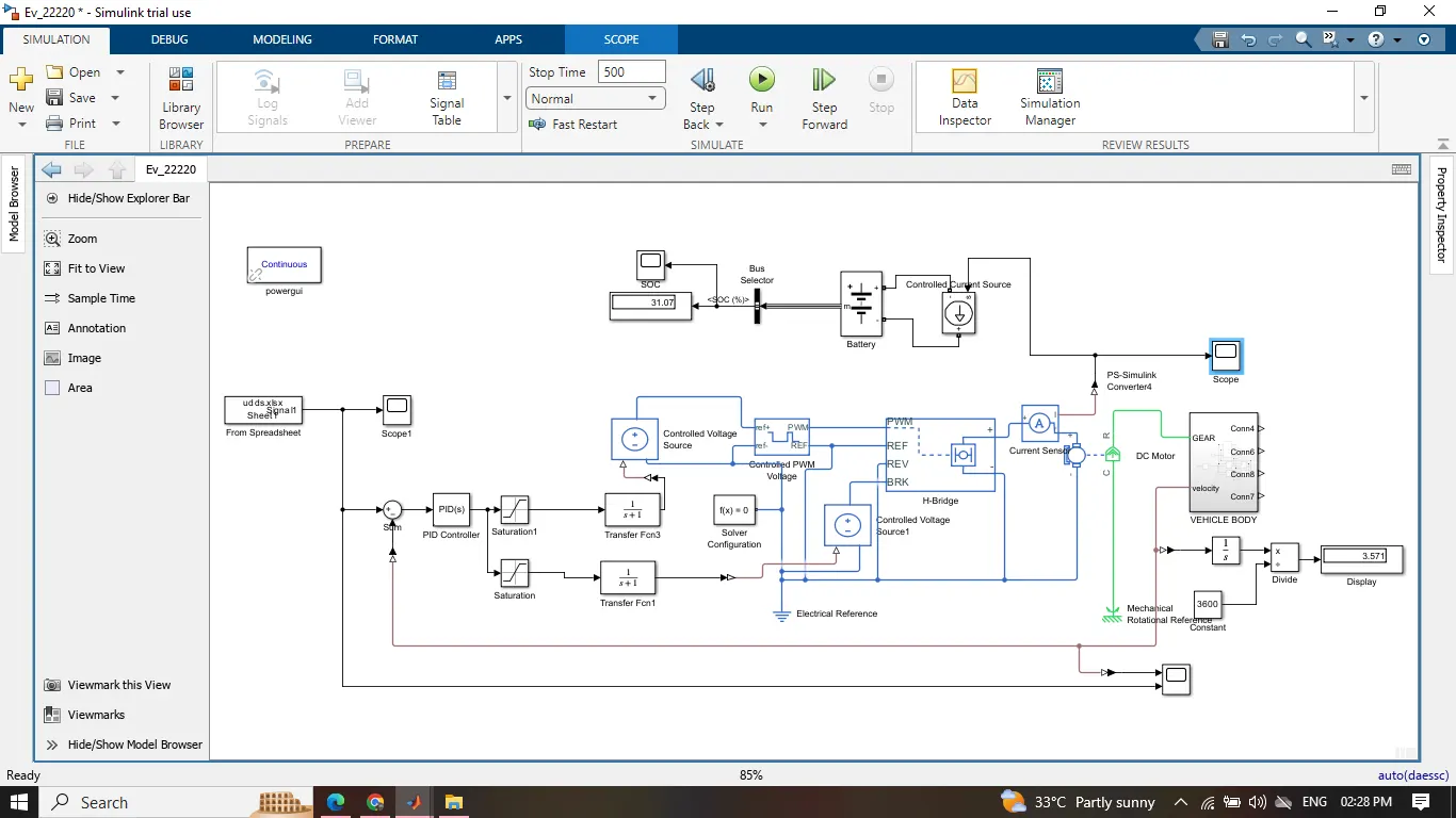
MODEL OF THE EV
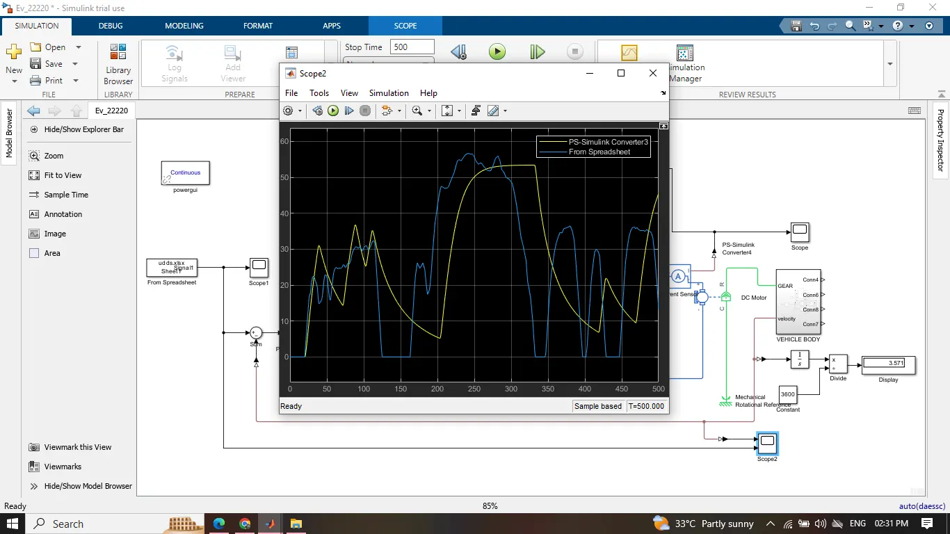
following driving cycle data and the model file inclosed with the answer body.