Final Project: Design of an Electric Vehicle
INTRODUCTION
Electric E-Rickshaw also known as electric tuk-tuk e-rickshaws and autos are going popular after 2018 in the Indian market. This E- Rikshaw is the best alternative to petrol/CNG auto rikshaw and human or horse-pulled rickshaws because of their low fuel cost, zero-emission, and less human effort.
The electrical system used in the Indian version is 48VDC can run9-0- km/full charge, top speed km/h, and this electric motor power range from 650-1400 Watts; the battery takes -8-10 hrs to become fully charged. Basic seating capacity is driver plus 4 passenger total of 5 person
Here basically, the E rikshaw is designed in MATLAB -SIMULINK Inthe designed electric rickshaw's main blocks are the battery, drive cycle, controlled, dc motor, vehicle body, and transmission system. drive cycle is the input of human effort that how he is going to drive his actual cycle, then we can use drive cycle like FTP75,WOT, or by using Excel.
THEORY
An electric Vehicle is a vehicle that use s or more eectric motors or traction motors for ropulsion.An electric vehicle may be powerd through a collector system by electricity from off- vehicle sources or may be self-contained with battery, solar panels,fuel cells or an electric generator to coonvert fuel to electricty.EVs include,but are not limited to road and rail vehicle surface and underwater vessels, electric aircraft and electric space craft.
COMPONENTS OF EV
EV engine have no need for the fuel engine and gear transmission the two of the most crucial component for internal combustion vehicle
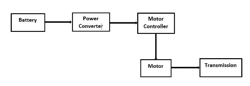
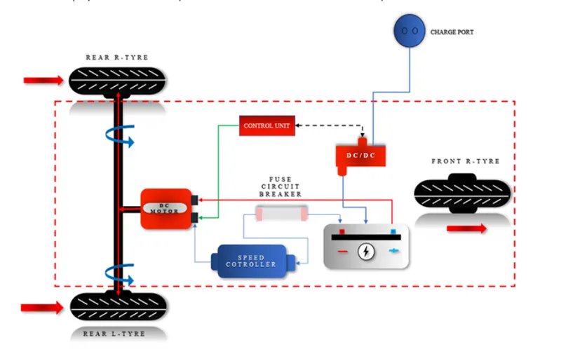
An electric powerd trycycle has three primary components- Battery,motor controller, and the electric motor
General detail of E- Rickshaw
| Battery-type Lithium ion |
60.8v,160Ah |
| Vehicle kerb weight | 260kgs |
| Load Capacity |
340kg |
| Vehicle speed | 70Kmph |
| Driving range | 140km(160Ah) |
| no of wheels per axel | 2 |
| Frontal area | 91m2 |
| Drag coefficient | 5 |
| wheel radius | 306m |
| Vertical load | 3000N |
- Electric Motor: PM brushed DC Motor type 650- 1400W & 48V (Input) motor is used. It is controlled via an electronic controller.
- Electronic Motor Controller: The controller includes a manual or automatic switch turning the motor on/off, selecting forward or reverse motion, selecting and regulating speed, regulating or limiting torque and protecting against overloads. It is connected to a battery pack and the controller feeds the input to the motor, lamp, AC/DC converter and Speedometer/ Indicator.
- Battery: A set of four 12V deep cycles /Li-ion batteries is used since the required voltage is 48V. These batteries are connected in series to the controller unit.
- Front Shock Absorbers: Helical Springs with dampeners with hydraulic telescopic shock absorbers are used.
- Rear Suspension: Leaf spring carriage spring with a rear shocker
- Brakes: Drum brakes, actuated internally, expanding shoe type are used. Brakes are mounted on the chassis (Pedal brakes), so on pressing the pedal, the brakes will engage stopping the rear wheels.
- Speedometer/Indicator: Speedometers generally used have analogue dials. The one on the left side indicates vehicle speed and the one on the right side indicates battery charge level. It is connected to the controller unit.
- Steering: Handlebar-type steering is used.
- Miscellaneous Spare parts: Centre locking, Alloy wheel, Rear light, Front glass, Front Indicator, Headlight, Ignition switch, Charger, Converter, left-right switch, Tyre, Wirings, Throttle set etc.
MODELING OF VEHICLE BODY SYSTEM
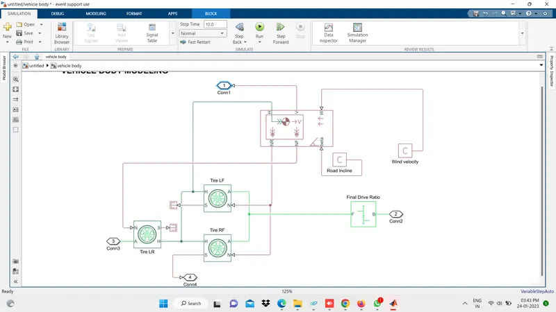
The above block consists of the body mass,aerodynamic drag, road incline, and weight distribution between axles due to the acceleration road profile.
In a given block
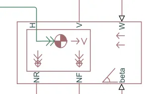
1.NR:it is physical signal output which is connected to the rear wheel axel and for this model, it is connected with a normal force of rear tire.
2.NF:it is a physical signal output which is connected to front wheel axeles and for this particulr model it is connected with the normal force acting on a front wheel tire
3.Beta: Beta is basically road inclined angle , here we can defined a constant value for road angle inclination
4.H: This part is a horizontal motion of a vehicle body.this connection will conected with all four hub of wheel for finding the thrust generated by the tire.
5.V: This port is the vehce longitudinal velocity.
6.W:it is a Head wind speed basicalu , we will define particular winf speed by adding consant block
vehicle body parameter
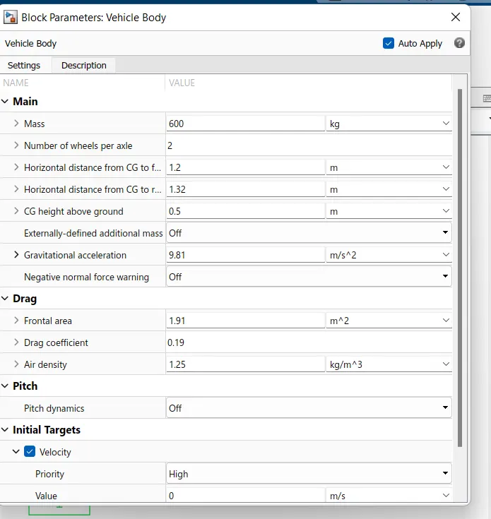
Details input of vehicle body
Main settings
1.Mass:600 kg
2.Number of wheels per axle;2
3.The horizondal distance from CG to front axle 1.2m
4.The horizandal distance from CG to the rear axle :1.32m
5. CG height above ground :0.5 m
6.Externally-defined additional mass:OFF
7.Gravitational acceleration:9.81m/s^2
negative normal force warning :OFF
- Frontal area: 1.91 m^2
- Drag coefficient: 0.19
- Air density: 1.25 kg/m^3
Pitch Setting
- Pitch dynamics: OFF
Variable Settings
- Beginning Value of Velocity: 0 m/s
Other connected detail
- Wind Velocity: 2.22222 m/s
- Road Incline: 0
TIRE
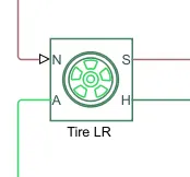
Tire parameter
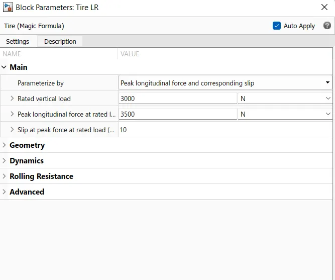
Rated vertical load=3000 N
Peak longitudinal force at rated load=3500N
Slip at peak force at rated load=10
Dc motor
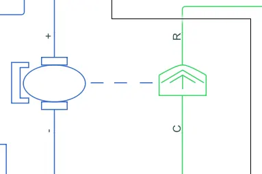
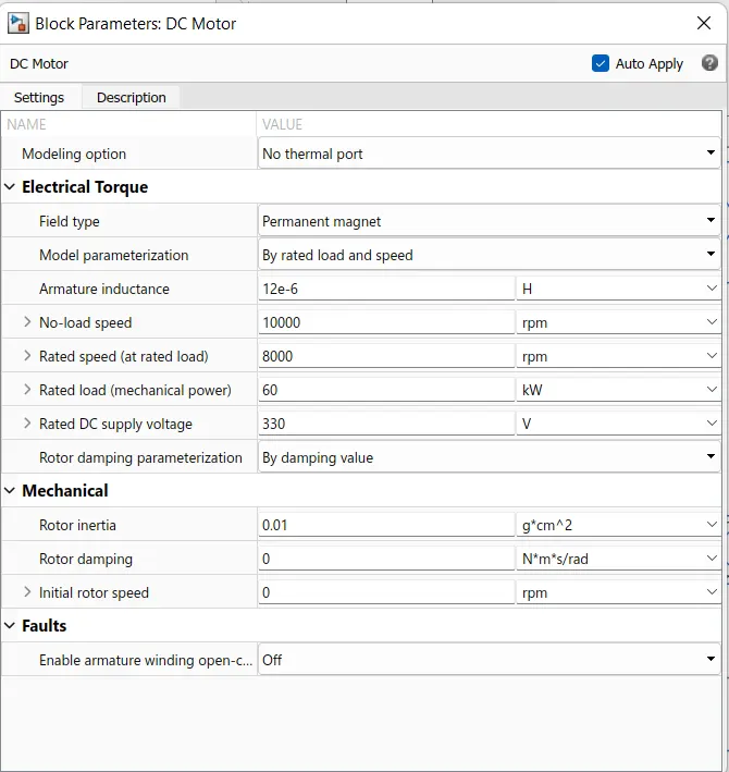
The motor field type is permenet magnet type dc motor
no load speed is 10000rpm
rated speed 8000rpm
rated load is 60kw
rated dc suply voltage 330v
rotor inertia 0.01
Here the blue colour corresponds the electrical side of the motor and the green colour corresponds to te mechanica side
The connection are represent the rotor of the motor and that is connected to the gear of the vehicle system ( input of the vehicle system ) .
The C port is connected o the mechanical rotational reference.
The + and - terminal of the motor is connected to the motor controller
If these terminals are directly connected to a battery, the required DC motor will run on the rated capacity of the battery. This will eventually result into no control over the DC motor and the vehicle will run at top speed throughout the simulation.
Thus, a motor controller is very much needed.
motor controller
H bridge circuit:
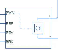
- This block represents an H-bridge motor drive. The block can be driven by the Controlled PWM Voltage block in PWM or Averaged mode.
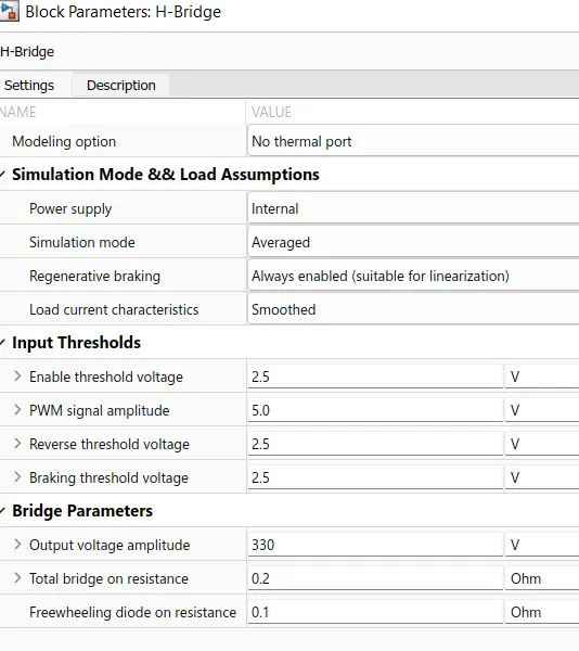
- In PWM mode, the motor is powered if the PWM port voltage is above the enabled threshold voltage.
- In Averaged mode, the PWM port voltage divided by the PWM signal amplitude parameter defines the ratio of the on-time to the PWM period.
- Connection REF is for the reference input. This combined with the PWM connected will form the pulse input for the H-Bridge.
Here, the REF input is connected to the Electrical Reference (ground). - Connection REV corresponds to the reverse motion of the motor which essentially means, the backward motion of the vehicle.
Here, the backward motion of the vehicle is not accounted for and so, the port is connected to the electrical reference. - Connection BRK is for the braking of the vehicle.
- Since, the PWM mode results in a huge amount of simulation time, Averaged mode is selected for this simulation.
- Load current characteristics are considered to be smoothed here.
- Also, the regenerative braking is anabled for the simulation. This means, when the vehicle starts decelerating, corresponding amount of charge will be fed back to the battery.
Accordingly, the BRK input is connected to a Controlled Voltage Source. This will generate emf corresponding to the intensity of brakes applied and fed the power back to the battery.
CONTROLLED PWM VOLTAGE
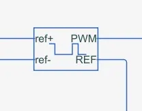
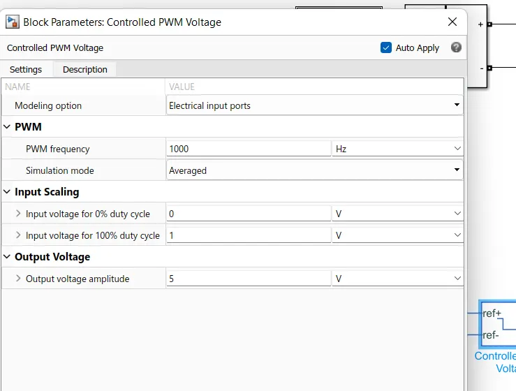
The PWM &REF connections are for the corresponding port on the H-Bridge circuit the 2 reference input correspond to the throttle input given by the driver . The block generates corresponding pulse width as per the acceleration and brakes aplied by the driver himself
Here the PWM frequency is 1000hz Also , the simulation mode is averaged as that inthe H-Bridge circuit
LONGITUDINAL DRIVER
Longitudinal Driver is an inbuilt block provided by the powertrain blockset