Final Project: Design of an Electric Vehicle
Electric Vehicle,
Electric vehicles have low running costs as they have less moving parts for maintaining and also very environmentally friendly as they use little or no fossil fuels (petrol or diesel). While some EVs used lead acid or nickel metal hydride batteries, the standard for modern battery electric vehicles is now considered to be lithium ion batteries as they have greater longevity and are excellent at retaining energy. In order to address the issue of rising pollution, global warming, depleting natural resources. Though the concept of electric vehicles has been around for a long time
Operation of Electric Vehicle,
1. The Electric Cars look the same as any regular fuel generated Cars, however the Plug in Cars don’t have the Tail Pipe or the Gas Tank. The source of the power of the Electric Car is the batteries which act as Gas Tank, supplying the Electric Motors the energy to run the vehicle. The battery’s Electrical energy gets converted in to Kinetic energy by the Motor of an Electric Car.
2. The user/driver turns on the car or powers the car. Selects “Forward” or “Reverse” option and steps on the accelerator pedal. Electric motor has only a single rotating element called the Potentiometer. The motion from the motor is transmitted to the car wheels through Controller. The power is controlled by Controller which helps determine which parts or accessories require more power and thereby helps in distribution of the battery energy.
3. If the Car has to move “Reverse” then the flow of electricity through the motor is reversed which changes the rotation of the Motor. This makes the wheels to rotate in the opposite direction. The Electric Cars have a Regenerative braking system along with conventional friction braking.
4. In Regenerative Braking System, when the User/Driver releases the accelerator pedal and pushes the brakes, the motor acts as a generator and converts Car’s kinetic energy to electrical energy which helps in recharging batteries. This process reduces the speed of the Car. The User can also apply the conventional Friction braking system for stopping the car immediately. The rest of the components like the Air Bags and Air Conditioning is the same as the fuel powered cars.
Objectives,
1. To make the most simple and low run-time vehicle model using individual components models.
2. To check the performance of Vehicle speed, Battery state of charge with various drive cycle i.e (Speed vs Time) inputs.
3. The main important inputs are motor power, and vehicle body (Rolling resistance, Air drag, mass).
4. To know Matlab models and their configuration to match with actual vehicle.
BLOCK DIAGRAM OF ELECTRIC VEHICLE:
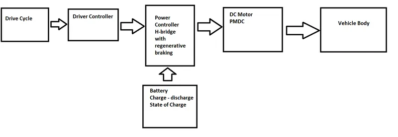
The Main Components of Electric Vehicle are,
1. Battery
2. Electric Motor
3. Gearbox
4. Wheels
5. Power Electronics Converter
6. Driver Controller
7. Vehicle body
Modeling in Simulink,
Subsystem Block Diagram
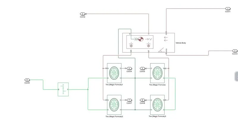
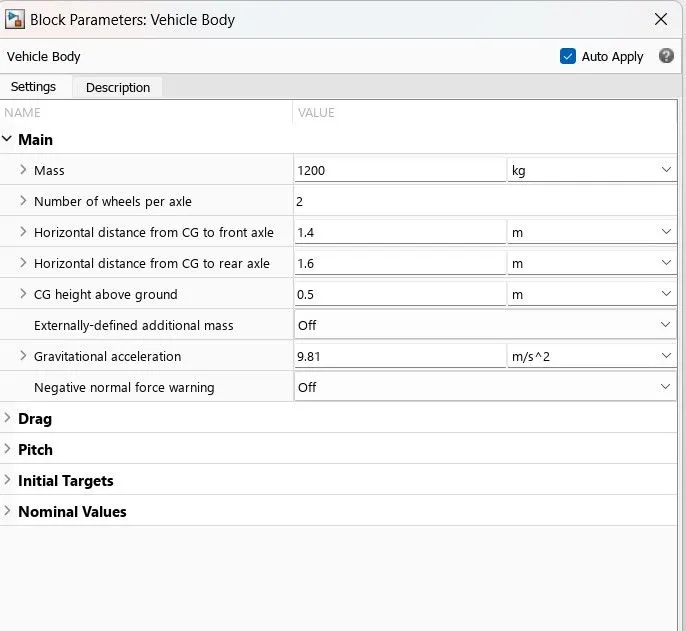
Vechile Body is a subsystem of Wheels, Vehcile Body, Gearbox
This block contain 6 ports which can be used to model various aspects of the vehicle body. The ports are mentioned below;
wheels, (Block - Tyre magic formula)
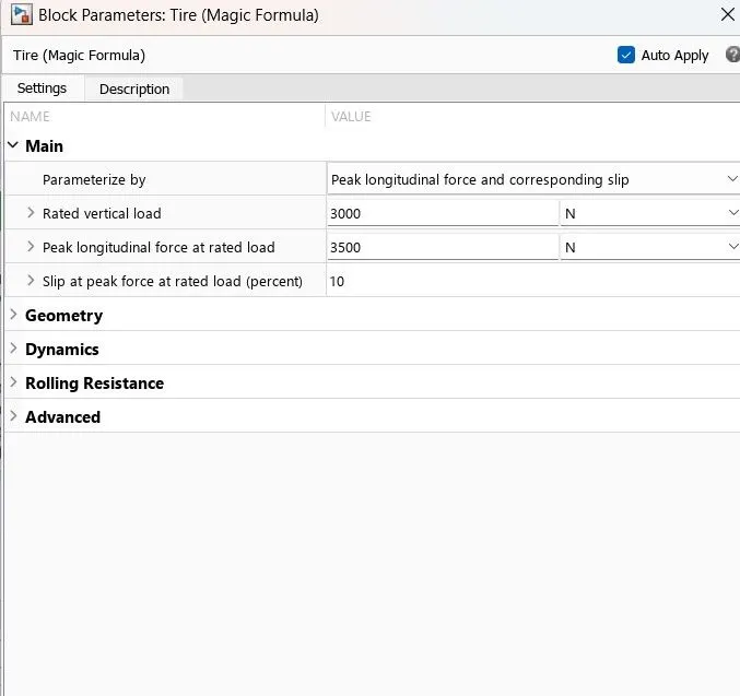
Four Terminals,
H - Hub
S - Tyre
N - Normal force
A - Axial connection
Vehicle Body,
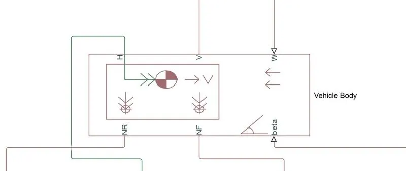
1. H- H Stand for hub it is used to connect the hub of wheels to the main body of the vehicle
2. V- Physical signal output port of velocity is used the velocity output of the vehicle
3. W- Physical input port used to wind velocity acts against the vehicle
4. NR- Physical signal output port used to connect the rare wheels
5. NS-Physical signal output port used to connect the front wheels
6. physical signal input port which allows the vehicle to undergo an inclination of hill-climbing force.
Gearbox,
 x
x
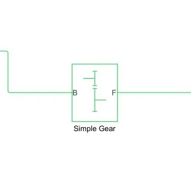
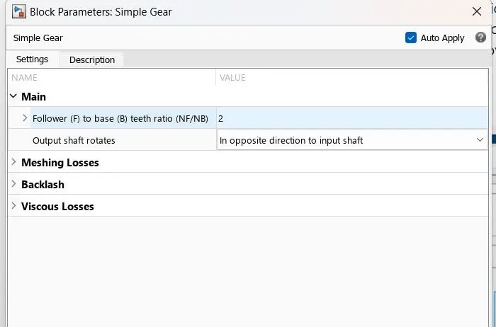
Gear Box is coupled to axel of wheels,
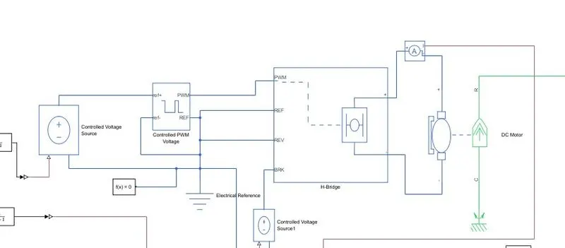
Motor and Controller system,
H - Bridge Block,
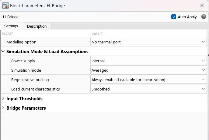
This is the Power Converter which needed to provide power and magnitude from one component to other, In EV System power converter is needed to provide a DC voltage from the battery of the EV to the DC motor, so that it can function properly at the required parameters. Here i have used an H-bridge motor drive as my power converter.
Terminals,
PWM - Pluse width modulation
Ref - Reference
Rev - Reverse
Brk - Brake
Controlled PWM Voltage,
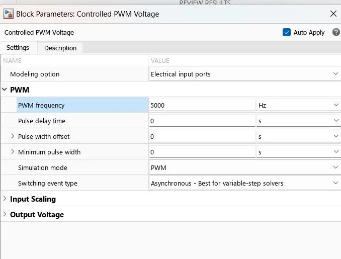
This block provides the necessary voltage that is powerfull enough to maintaion the voltage at the output regardless of the current that passes through it.In this subsystem control voltage blocks have been used. One block is used for acceleration and other to provide the voltage for deacceleration.
Electrical Reference Block,
Electrical reference block is used to create grounding effect for electrical circuits.
Solver Configuration,
A solver configuration block is used to solve any necessary equations in a model.
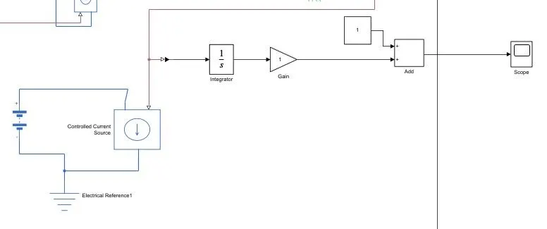
The Battery will be the energy store of the EV and will contain the electrical energy in DC form and provide this energy to operate.
SOC - State of Charge,
1. This SOC is to measure the state of charge of the battery, a sub-system was created of various blocks. The first block is integrator block used to integrate the value of the current signal with respect to time and
2. The Gain block is used in order to multiply the signal coming from the integrator block. This block will divide the current signal with the ampere rating of the battery which is Ah*3600(secs in hour).
3. Assuming the battery is always fully charged I have added the constant block with a value of 1 representing 100%.Next a sum block is used to perform addition operations into a subsystem called SOC estimate.
Distance Measurement Subsystem Block,
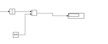
Distance measurement,
To measure the distance traveled by the vehicle. First, we had to add the integrator block to integrate the velocity signal that is output from the velocity sub-system. Divide block along with constant block having a value of 3600 is used to divide the integrated speed. This will give us the distance traveled in kilometers in displace block.
Signal Builder (Drive Cycle),
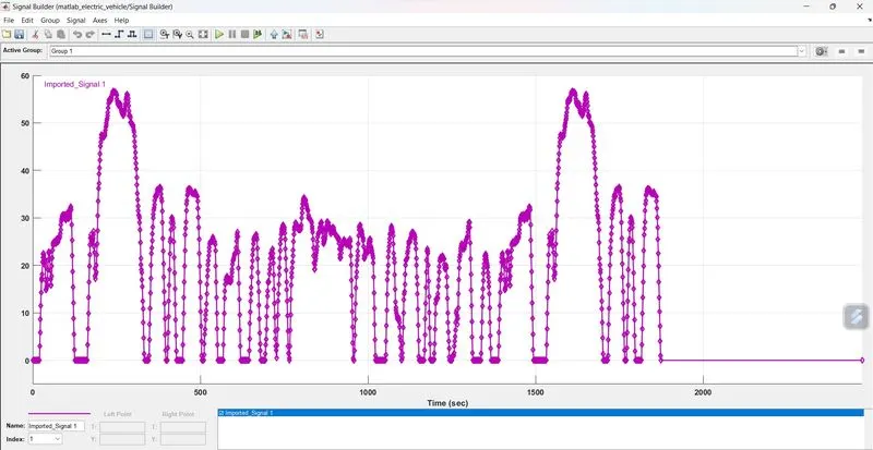
Excel File is Imported into the simulation of Signal Builder as per the above-plotted data, (Excel File Attached)
Multiport Switch,
This block is used to connect one or more inputs to perform the operation.
Driver Block (PID Controller),
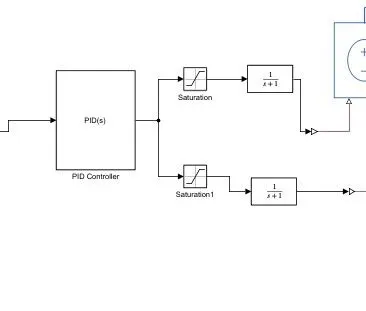
This block implements continuous- and discrete-time PID control algorithms and includes advanced features such as anti-windup, external reset, and signal tracking. You can tune the PID gains automatically using the Tune button.