Final Project: Design of an Electric Vehicle
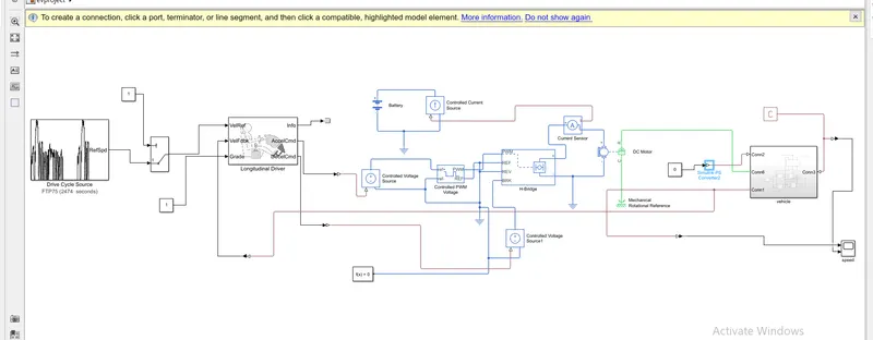
below screenshot represents the matlab model of EV which uses DC motor and the battery
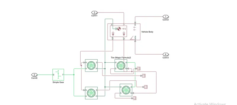
below screenshot represents blocks inside the vehicle subsystem
vehicle body block
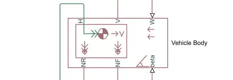
*this block contain 6 ports which can be used to model various aspects of the vehicle body
*H- This stands for hub and is used to connect the hubs of the wheels to the main body of the vehicle
*V-Physical signal output port which stands for 'velocity' and is used the output the velocity of the vehicle
*W- Physical signal input port and allows us to model a wind velocity that acts aginst the vehicle
*NR- Physical signal output port to connect to connect the rear wheels
*NF- Physical signal output port to connect the front wheels of the vehicle
*Beta- Physicall signall input port which allows the vehicle to undergo an inclination of hill climbing force
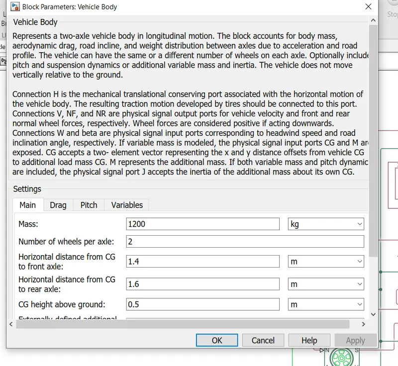
model parameters are used to set up mass, frontal area and others
tire(magic formula)
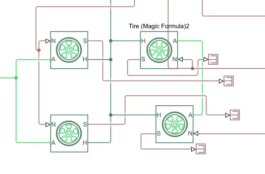
*this block represents the longitudinal behavior of a tire of a highway
*connection A is the mechanical rotational port for the wheel axle. Connection H is the mechanical translational port for the wheel hub through which the thrust developed by the tire is applied to the vehicle
*connection N is a physical signal input port that applies the normal force acting on the tire. The force is considered positive if it acts downwards. Connection S is a physical signal output port that reports the tire slip
*fxour tires are connected, where the right two tires are the rear wheels and the remaining two are the front wheels . they are interconnected to the hub of the vehicle body block. and their respective axles are connected accordingly. We here have connected the rear axle with the gear as we want the model to be a rear wheel drive vehicle
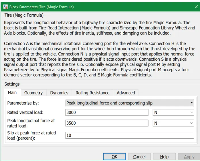
in this parameter we can change the geometry , dynamics, rolling resistance other characteristics
simple gear
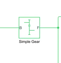
this block represents a fixed-ratio gear or gear box. Connections B (base) and F (follower) are mechanical rotational conserving ports. The base is the input port and the follower is the output port
motor and controller system
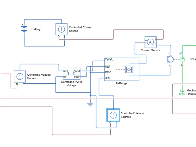
blocks used in this system are
*DC Motor
*H-bridge
*Controlled PWM voltage
*Controlled voltage source
DC motor
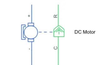
* there are two sides of the block , the mechanical side is on the right and the electrical side is on the left. mechanical side has tow ports C and R, C stands for casing and is the stable part and R is the rotor which produces a torque
*the electrical side has a positive and negetive side for the voltages to be applied. if positive voltage is applied to the motor block from the positive to the negetive terminal then a positive torque will act from C to R port
*the direction of the torque can be cahnged by changing the sign of the back emf or the torque constant. Here i have connected the c port to the mechanical rotational reference because it will be stationary. the R port is connected to the gear in the vehicle body block
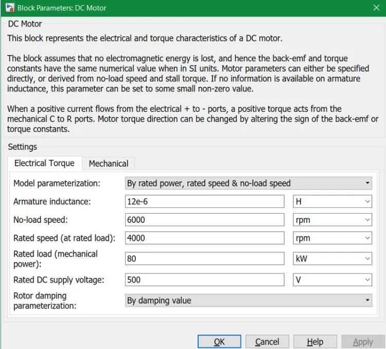
for the simulation the rated load and speed parameterization option is selected where the no-load speed, rated speed, rated load and DC supply voltage are set. the rated power must be changed from V (default) to kW
H bridge
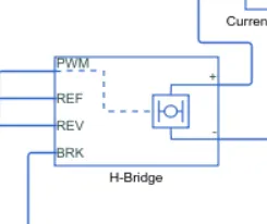
*PWM (Phase Width Modulation) where the H-Bridge block output is a controlled voltage that depends on the input signal at the PWM port and Averaged which consists of two load current characteristics being smoothed and unsmooth or discontinuous
*the first port (PWM) is the input port, the second port (REF) is to connect the electrical reference block. The third port (REV) controls the reverse polarity of the block and the fourth port (BRK) controls the short circuit of the block
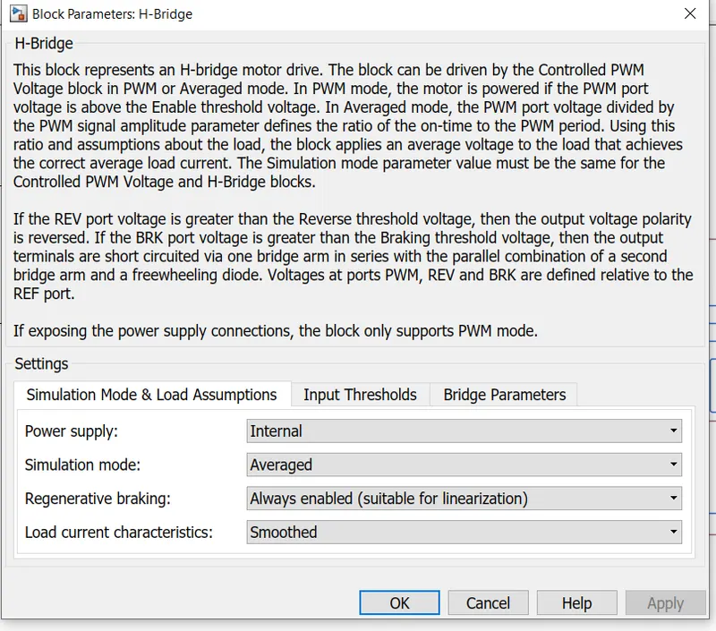
for the simulation, the averaged mode is taken into consideration, the regenerative braking parameter is enabled and the smoothed load current characteristics is defined
controlled pwm voltage
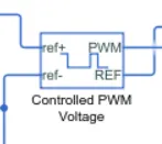
*this block creates a Pulse-Width Modulated (PWM) voltage across the PWM and REF ports
* the output voltage is zero when the pulse is low, and is equal to the Output voltage amplitude parameter when high. Duty cycle is set by the input value
The PWM and REF ports are connected to the ports of the same in the H-bridge block
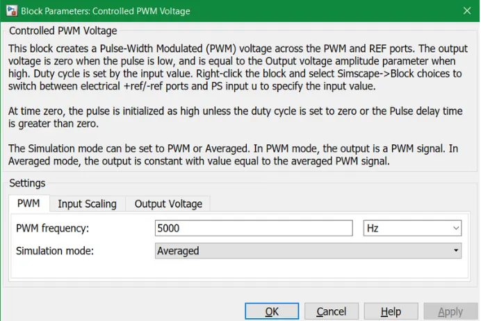
here all the parameters are set to their default values
controlled voltage source
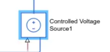
*two voltage source blocks are used for the simulation,one to control acceleration which is connected to the ref+ port of the PWM block and the second for regenerative braking which is connected to the BRK port of the H-bridge block
battery block
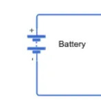
battery will be the energy store of the EV and will contain the electrical energy in DC form and provide this energy to operate
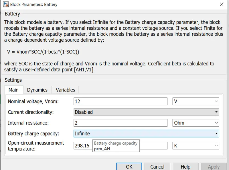
all the parameters are set to be default
controlled current source
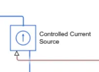
this block represents an ideal current source that is powerful enough to maintain the specified current through it regardless of the voltage across it.the output current is I = Is, where Is is the numerical value presented at the physical signal port
*it is connected to the positive and negative terminals of the battery
current sensor block
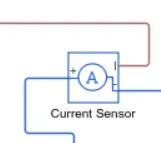
*this block represents an ideal current sensor, that is, a device that converts current measured in any electrical branch into a physical signal proportional to the current
*connections + and - are conserving electrical ports through which the sensor is inserted into the circuit. connection I is a physical signal port that outputs current value
* terminals of the current sensor are connected between the H bridge block and the DC motor
drive cycle block
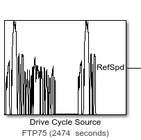
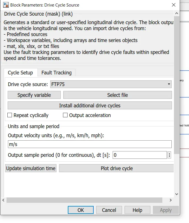
this block is used for the input which represents a drive cycle. the drive cycle used for this simulation is the FTP75 which stands for Federal Test Procedure. all the parameters are set to default
longitudinal driver block
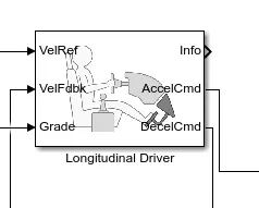
*block that is used as a controller for driver based inputs which are acceleration and braking
*the output port (RefSpd) of the drive cycle block is connected to the VelRef port which calculates the input parameters
*the VelFdbk port is connected to the velocity port (V) of the vehicle body block from the subsytem and also the scope in order to plot the input data
*the Grade port is set to 1 by using a constant block
*the AccelCmd and DecelCmd ports which are the outputs for acceleration and braking respectively are connected to the respective controlled voltage source blocks responsible for acceleration and regenerative braking
result
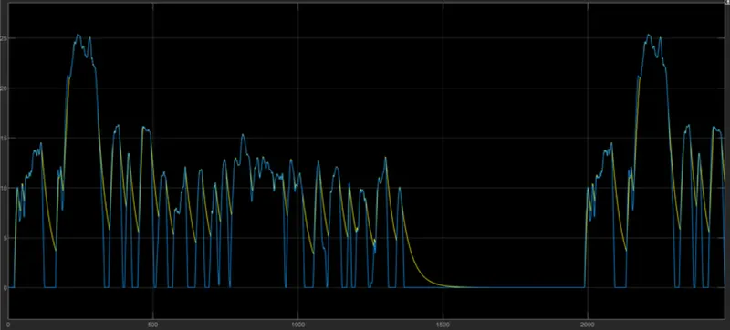
*scope is used to plot the speed of the electric vehicle which compares the actual drive cycle to the input drive cycle
*simulation is run for 2474 seconds which is the standard time of the FTP75 drive cycle
*the blue line represents the input speed and the yellow line represents the output or actual speed
*it can be observed that the vehicle follows the same pattern of acceleration and coasting as the input drive cycle which can be noted from the overlapping lines
*the gradual curves of the yellow line which do not overlap with the input indicates the regenerative braking of the electric vehicle in effect
conclusion
using simulink a matlab model of an electric vehicle has been created with the blocks used explained and the impact of the driving cycle on the vehicle's speed is analysed