Final Project: Design of an Electric Vehicle
Electric Vehicle (EV)
An electric vehicle (EV) is a vehicle that uses one or more electric motors or traction motors for propulsion. An electric vehicle may be powered through a collector system by electricity from off-vehicle sources or may be self-contained with a battery, solar panels, fuel cells or an electric generator to convert fuel to electricity. EVs include, but are not limited to, road and rail vehicles, surface and underwater vessels, electric aircraft and electric spacecraft.
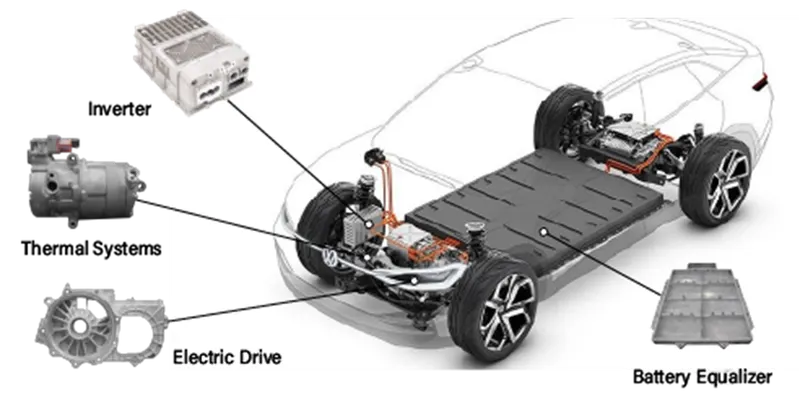
EVs first came into existence in the mid-19th century, when electricity was among the preferred methods for motor vehicle propulsion, providing a level of comfort and ease of operation that could not be achieved by the gasoline cars of the time. Internal combustion engines were the dominant propulsion method for cars and trucks for about 100 years, but electric power remained commonplace in other vehicle types, such as trains and smaller vehicles of all types.
Commonly, the term EV is used to refer to an electric car. In the 21st century, EVs have seen a resurgence due to technological developments, and an increased focus on renewable energy and the potential reduction of transportation's impact on climate change and other environmental issues. Project Drawdown describes electric vehicles as one of the 100 best contemporary solutions for addressing climate change.
component of the electrical vehicle :
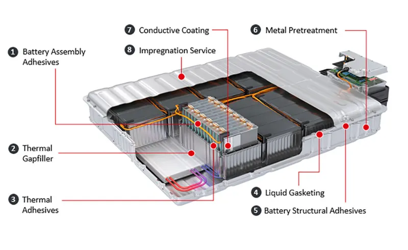
Battery:-
- Most electric vehicles use lithium-ion batteries (Li-Ions or LIBs). Lithium-ion batteries have a higher energy density, longer life span and higher power density than most other practical batteries. Complicating factors include safety, durability, thermal breakdown and cost. Li-ion batteries should be used within the safe temperature and voltage ranges in order to operate safely and efficiently.
- Increasing the battery's lifespan decreases effective costs. One technique is to operate a subset of the battery cells at a time and switching these subsets.
- In the past, nickel-metal hydride battery batteries were used in some electric cars, such as those made by General Motors. These battery types are considered outdated due to their tendencies to self-discharge in the heat. Furthermore, a patent for this type of battery was held by Chevron, which created a problem for their widespread development. These factors, coupled with their high cost, have led to lithium-ion batteries leading as the predominant battery for EVs.
- The prices of lithium-ion batteries are constantly decreasing, contributing to a reduction in the price of electric vehicles.
Electrical Motor:-
- The power of a vehicle's electric motor, as in other machines, is measured in kilowatts (kW). Electric motors can deliver their maximum torque over a wide RPM range.
- This means that the performance of a vehicle with a 100 kW electric motor exceeds that of a vehicle with a 100 kW internal combustion engine, which can only deliver its maximum torque within a limited range of engine speed.
- The efficiency of charging varies considerably depending on the type of charger, and energy is lost during the process of converting the electrical energy to mechanical energy.
- Usually, direct current (DC) electricity is fed into a DC/AC inverter where it is converted to alternating current (AC) electricity and this AC electricity is connected to a 3-phase AC motor.
- For electric trains, forklift trucks, and some electric cars, DC motors are often used. In some cases, universal motors are used, and then AC or DC may be employed. In recent production vehicles, various motor types have been implemented; for instance, induction motors within Tesla Motor vehicles and permanent magnet machines in the Nissan Leaf and Chevrolet Bolt
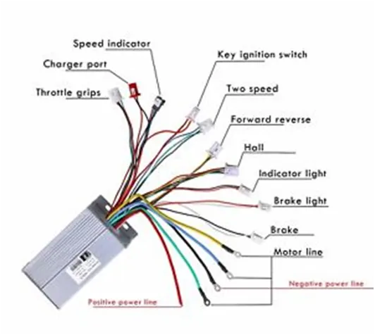
Motor Controller:
-
The motor controller of an electric car administers its complete operation and the distribution of its power at any given moment. It acts as a floodgate between the motor and batteries.
-
It helps monitor and regulates all key performance indications such as the vehicle's operator, motor, battery, and accelerator pedal. It has a microprocessor that can limit or redirect current.
-
It is used to either improve the mechanical performance of the car or suit the operator's driving style. There are also more refined controllers which are capable of greater accuracy and thus, higher efficiency.
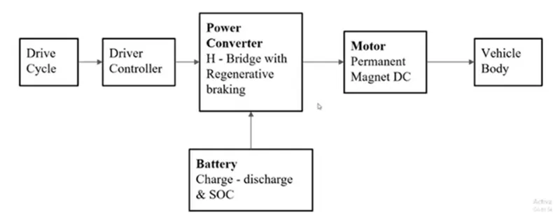
Drive cycle: A driving cycle is a series of data points representing the speed of a vehicle versus time. Driving cycles are produced by different countries and organizations to assess the performance of vehicles in various ways, as for instance fuel consumption, electric vehicle autonomy and polluting emissions.
Driver controller: The controller transforms the battery's direct current into alternating current (for AC motors only) and regulates the energy flow from the battery. In the early electric vehicles with DC motors, a simple variable-resistor-type controller controlled the acceleration and speed of the vehicle.
Power converter: In electric engineering, a DC to DC converter is a category of power converters and it is an electric circuit which converts a source of direct current (DC) from one voltage level to another, by storing the input energy temporarily and then releasing that energy to the output at a different voltage.
Vehicle body: Car bodies are most often made of steel, which is strong and durable, but also pretty heavy—especially for electric power to move on its own.
EV model in simulink:
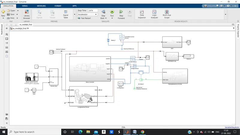
Explaination of blocks used in model:
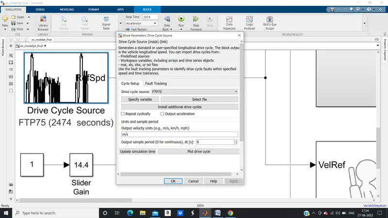
Drive cycle source: The Drive Cycle Source block generates a standard or user-specified longitudinal drive cycle. The block output is the specified vehicle longitudinal speed, which you can use to:
- Predict the engine torque and fuel consumption that a vehicle requires to achieve desired speed and acceleration for a given gear shift reference.
- Produce realistic velocity and shift references for closed loop acceleration and braking commands for vehicle control and plant models.
- Study, tune, and optimize vehicle control, system performance, and system robustness over multiple drive cycles.
Drive cycles from predefined sources. By default, the block includes the FTP–75 drive cycle
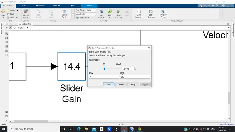
Slider gain: The Slider Gain block performs a scalar gain that you can modify during simulation. Modify the gain using the slider parameter.
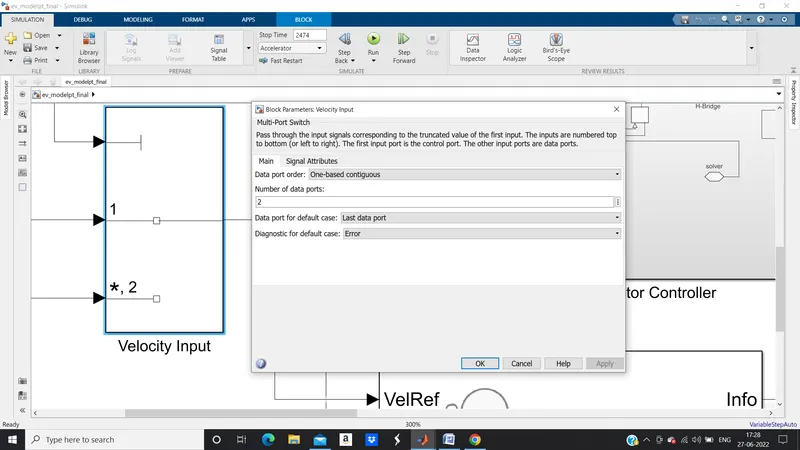
Multiport switch: Pass through the input signals corresponding to the truncated value of the first input. The inputs are numbered top to bottom (or left to right). The first input port is the control port. The other input ports are data ports.
Motor Controller:
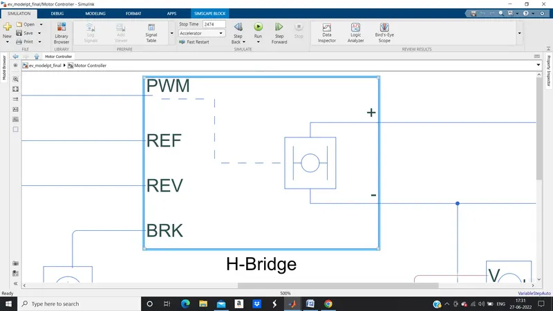
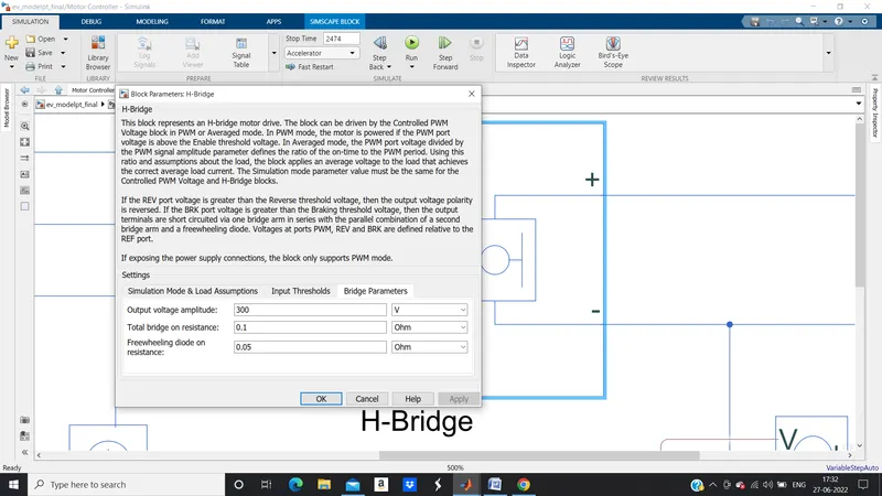
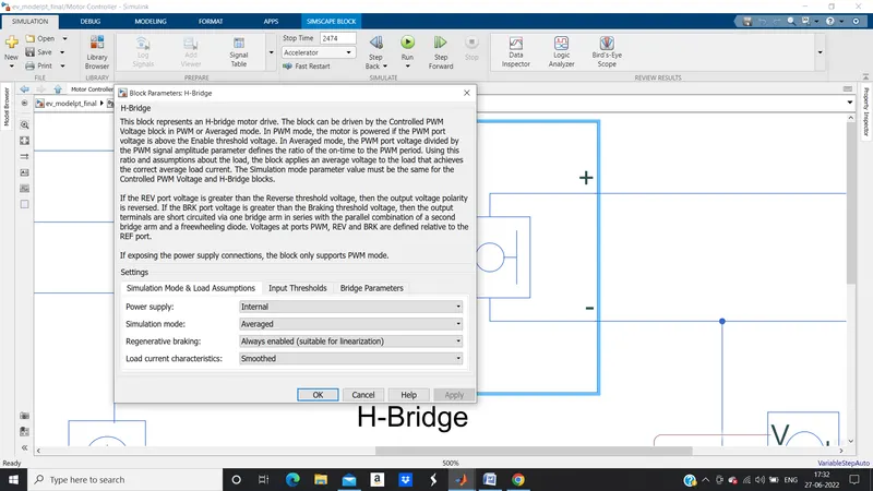
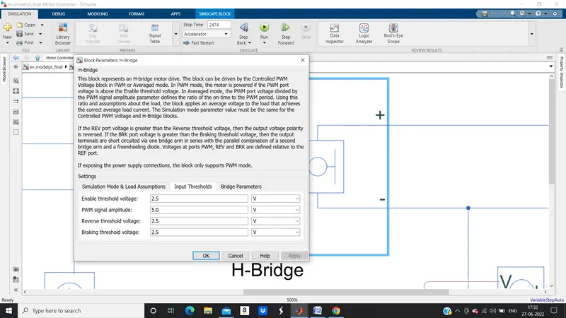
(i) H - Bridge: This block represents an H-bridge motor drive. The block can be driven by the Controlled PWM Voltage block in PWM or Averaged mode. In PWM mode, the motor is powered if the PWM port voltage is above the Enable threshold voltage. In Averaged mode, the PWM port voltage divided by the PWM signal amplitude parameter defines the ratio of the on-time to the PWM period. Using this ratio and assumptions about the load, the block applies an average voltage to the load that achieves the correct average load current. The Simulation mode parameter value must be the same for the Controlled PWM Voltage and H-Bridge blocks.
If the REV port voltage is greater than the Reverse threshold voltage, then the output voltage polarity is reversed. If the BRK port voltage is greater than the Braking threshold voltage, then the output terminals are short circuited via one bridge arm in series with the parallel combination of a second bridge arm and a freewheeling diode. Voltages at ports PWM, REV and BRK are defined relative to the REF port.
If exposing the power supply connections, the block only supports PWM mode.
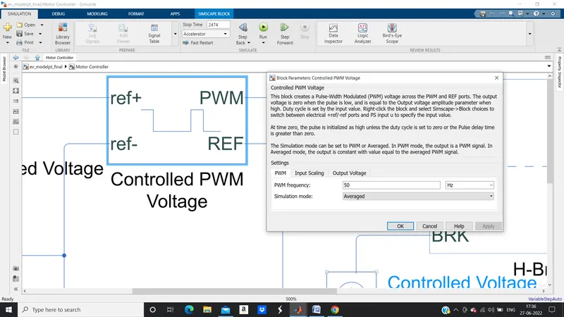
(ii) Controlled PWM Voltage: This block creates a Pulse-Width Modulated (PWM) voltage across the PWM and REF ports. The output voltage is zero when the pulse is low, and is equal to the Output voltage amplitude parameter when high. Duty cycle is set by the input value. Right-click the block and select Simscape->Block choices to switch between electrical +ref/-ref ports and PS input u to specify the input value.
At time zero, the pulse is initialized as high unless the duty cycle is set to zero or the Pulse delay time is greater than zero.
The Simulation mode can be set to PWM or Averaged. In PWM mode, the output is a PWM signal. In Averaged mode, the output is constant with value equal to the averaged PWM signal.
(iii) Controlled voltage source: The block represents an ideal voltage source that is powerful enough to maintain the specified voltage at its output regardless of the current passing through it. The output voltage is V = Vs, where Vs is the numerical value presented at the physical signal port.
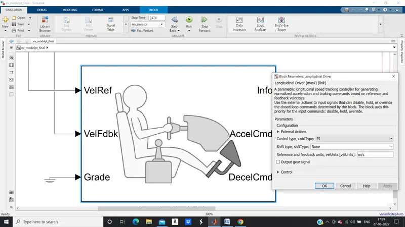
Longitudinal driver: A parametric longitudinal speed tracking controller for generating normalized acceleration and braking commands based on reference and feedback velocities. Use the external actions to input signals that can disable, hold, or override the closed-loop commands determined by the block. The block uses this priority for the input commands: disable, hold, override.
DC motor:
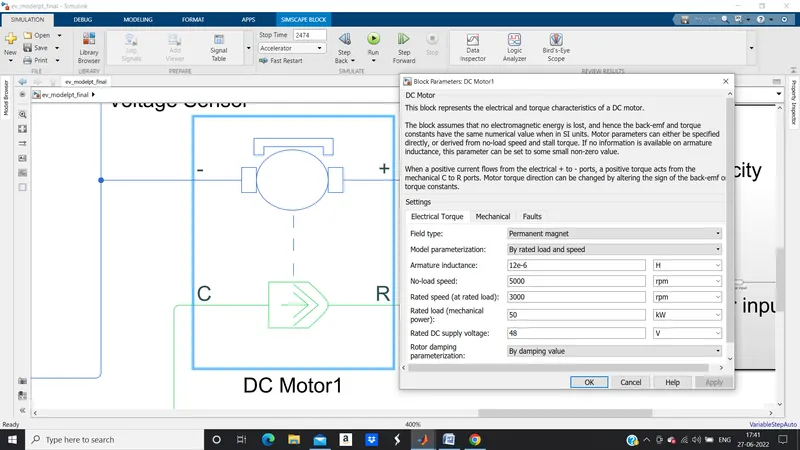
- This block represents the electrical and torque characteristics of a DC motor.
- The block assumes that no electromagnetic energy is lost, and hence the back-emf and torque constants have the same numerical value when in SI units. Motor parameters can either be specified directly, or derived from no-load speed and stall torque. If no information is available on armature inductance, this parameter can be set to some small non-zero value.
- When a positive current flows from the electrical + to - ports, a positive torque acts from the mechanical C to R ports. Motor torque direction can be changed by altering the sign of the back-emf or torque constants.
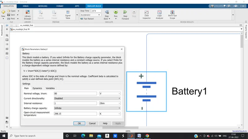
Battery: This block models a battery. If you select Infinite for the Battery charge capacity parameter, the block models the battery as a series internal resistance and a constant voltage source. If you select Finite for the Battery charge capacity parameter, the block models the battery as a series internal resistance plus a charge-dependent voltage source.
Transmission system:
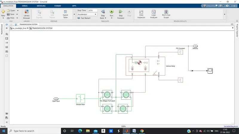
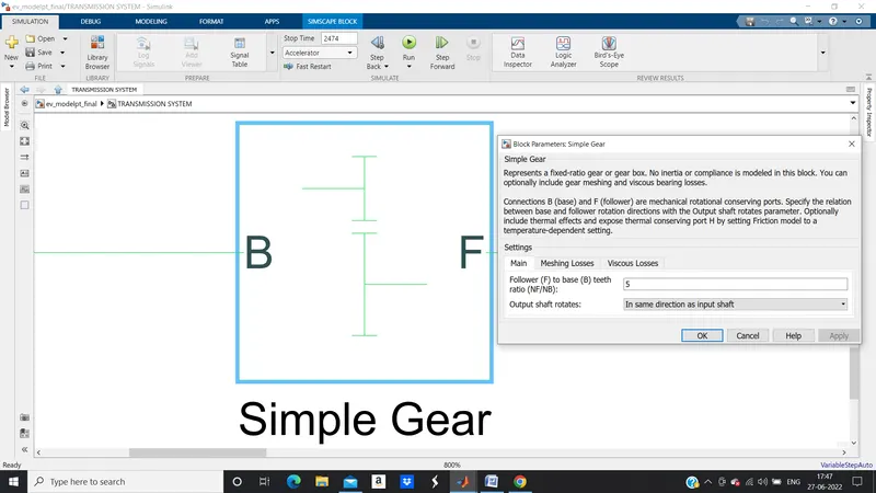
1.Simple gear: Represents a fixed-ratio gear or gear box. No inertia or compliance is modeled in this block. You can optionally include gear meshing and viscous bearing losses.
Connections B (base) and F (follower) are mechanical rotational conserving ports. Specify the relation between base and follower rotation directions with the Output shaft rotates parameter. Optionally include thermal effects and expose thermal conserving port H by right-clicking on the block and selecting Simscape block choices to switch between variants.
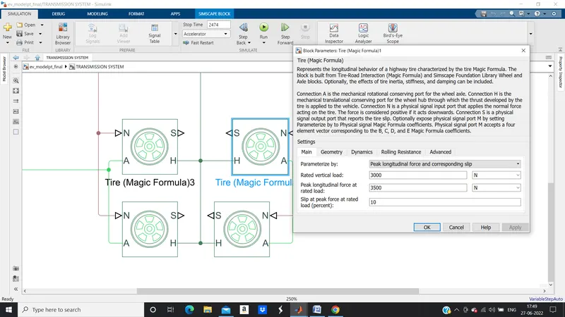
2.Tire (magic formula): Represents the longitudinal behavior of a highway tire characterized by the tire Magic Formula. The block is built from Tire-Road Interaction (Magic Formula) and Simscape Foundation Library Wheel and Axle blocks. Optionally, the effects of tire inertia, stiffness, and damping can be included.
Represents the longitudinal behavior of a highway tire characterized by the tire Magic Formula. The block is built from Tire-Road Interaction (Magic Formula) and Simscape Foundation Library Wheel and Axle blocks. Optionally, the effects of tire inertia, stiffness, and damping can be included.
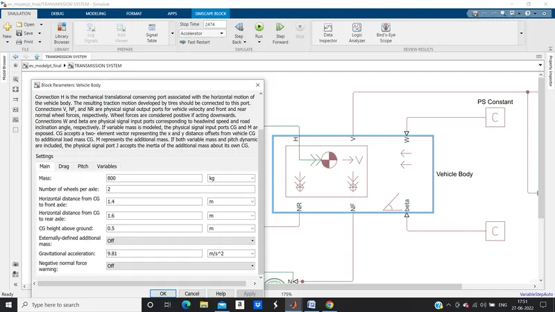
Vehicle body: Represents a two-axle vehicle body in longitudinal motion. The block accounts for body mass, aerodynamic drag, road incline, and weight distribution between axles due to acceleration and road profile. The vehicle can have the same or a different number of wheels on each axle. Optionally include pitch and suspension dynamics or additional variable mass and inertia. The vehicle does not move vertically relative to the ground.
Connection H is the mechanical translational conserving port associated with the horizontal motion of the vehicle body. The resulting traction motion developed by tires should be connected to this port. Connections V, NF, and NR are physical signal output ports for vehicle velocity and front and rear normal wheel forces, respectively. Wheel forces are considered positive if acting downwards. Connections W and beta are physical signal input ports corresponding to headwind speed and road inclination angle, respectively. If variable mass is modeled, the physical signal input ports CG and M are exposed. CG accepts a two- element vector representing the x and y distance offsets from vehicle CG to additional load mass CG. M represents the additional mass. If both variable mass and pitch dynamics are included, the physical signal port J accepts the inertia of the additional mass about its own CG.
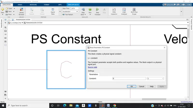
PS constant: This block creates a physical signal constant, the Constant parameter accepts both positive and negative values. The block output is a physical signal port.
Battery State of Charge (SOC):
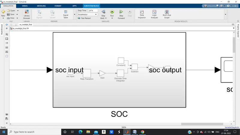
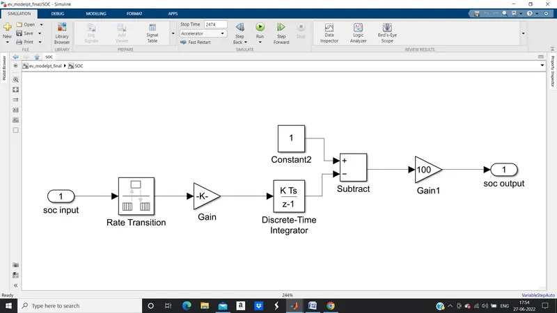
Rate Transition: Handle data transfer between different rates and tasks.
Gain: The Gain block multiplies the input by a constant value (gain). The input and the gain can each be a scalar, vector, or matrix.
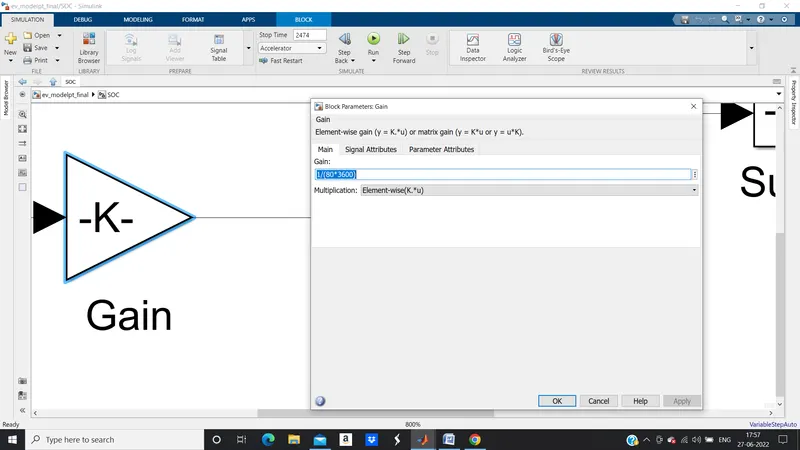
Discrete-Time integrator: Use the Discrete-Time Integrator block in place of the integrator block to create a purely discrete model.
Subtract: The Sum block performs addition or subtraction on its inputs. The Add, Subtract, Sum of Elements, and Sum blocks are identical blocks. This block can add or subtract scalar, vector, or matrix inputs. It can also collapse the elements of a signal and perform a summation.
Constant: Output the constant specified by the 'Constant value' parameter. If 'Constant value' is a vector and 'Interpret vector parameters as 1-D' is on, treat the constant value as a 1-D array. Otherwise, output a matrix with the same dimensions as the constant value.
Distance calculation:
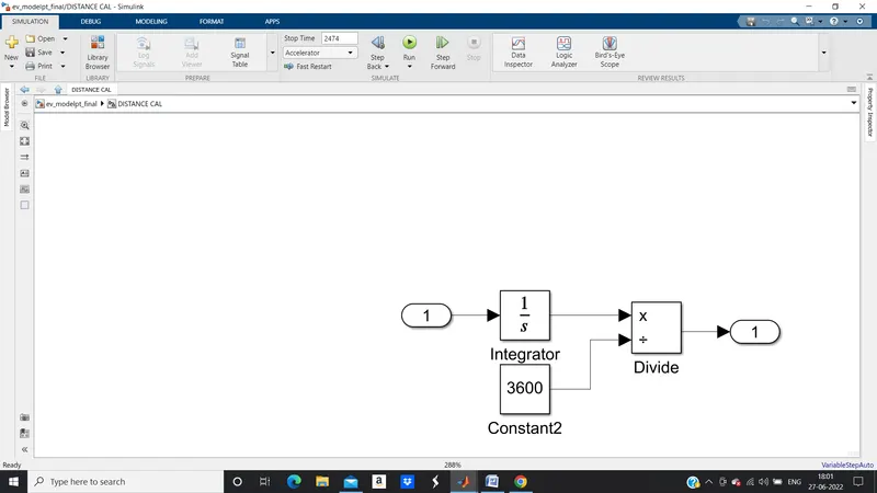
- Integrator: The Integrator block outputs the value of the integral of its input signal with respect to time
- Divide: The Product block outputs the result of multiplying two inputs: two scalars, a scalar and a nonscalar, or two nonscalars that have the same dimensions.
- Scope:The real-time Scope block acquires data in chunks of size Number of samples from the real-time application that is executing on the target computer.

- Display: Display input values. If the incoming signal is of type string, the 'Numeric display format' parameter selection does not affect the display of the string.
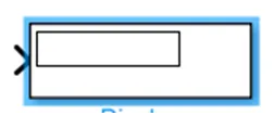
- Voltage sensor: The block represents an ideal voltage sensor, that is, a device that converts voltage measured between any electrical connections into a physical signal proportional to the voltage. Connections + and - are conserving electrical ports through which the sensor is connected to the circuit. Connection V is a physical signal port that outputs voltage value.
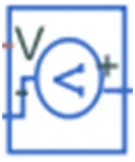
- Current sensor: The block represents an ideal current sensor, that is, a device that converts current measured in any electrical branch into a physical signal proportional to the current. Connections + and - are conserving electrical ports through which the sensor is inserted into the circuit. Connection I is a physical signal port that outputs current value.
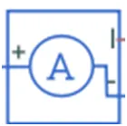
- Controlled current source: The block represents an ideal current source that is powerful enough to maintain the specified current through it regardless of the voltage across it. The output current is I = Is, where Is is the numerical value presented at the physical signal port.
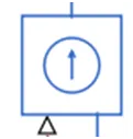
- PS-Simulink and Simulink-PS Converter:
Converts the input Physical Signal to a Simulink output signal.
Converts the Simulink input signal to a Physical Signal.
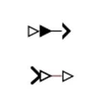
- Mechanical rotational reference: This block represents a mechanical rotational reference point, that is, a frame or a ground. Use it to connect mechanical rotational ports that are rigidly affixed to the frame (ground).

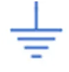
- Electrical reference: Electrical reference port. A model must contain at least one electrical reference port (electrical ground).
Simulink Results:
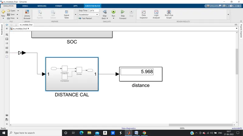
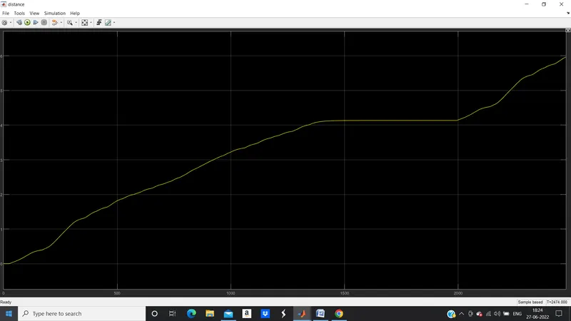
Total distance travelled is 5.96 Km.
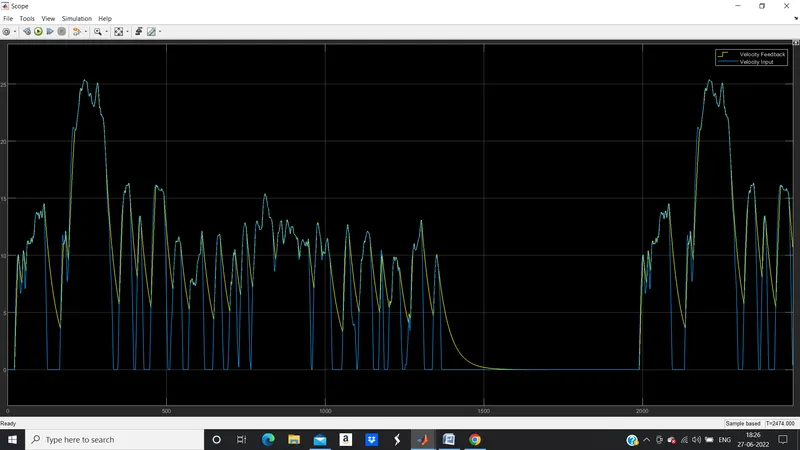
FTP-75 Drive cycle: As represented on the plot given above the yellow curve shows the drive cycle data, as we know that the FTP-75 Drive cycle operates on the full throttle for some seconds and then the drive cycle is turned to 0 this in case operates the vehicle and accelerates the car at the top speed for the initial stage and throttles the car at the maximum, though the vehicle is unable to match the speed of the vehicle with the drive cycle but it is running at its peak and then comes the phase where the acceleration is left now the vehicle is operated on the free wheeling mode, the vehicle is not powered and the vehicle runs on the speed which is sustained. The important point to note here is the vehicle does not come to rest in 2474 seconds, the vehicles speed is reduced but it does not come to 0.
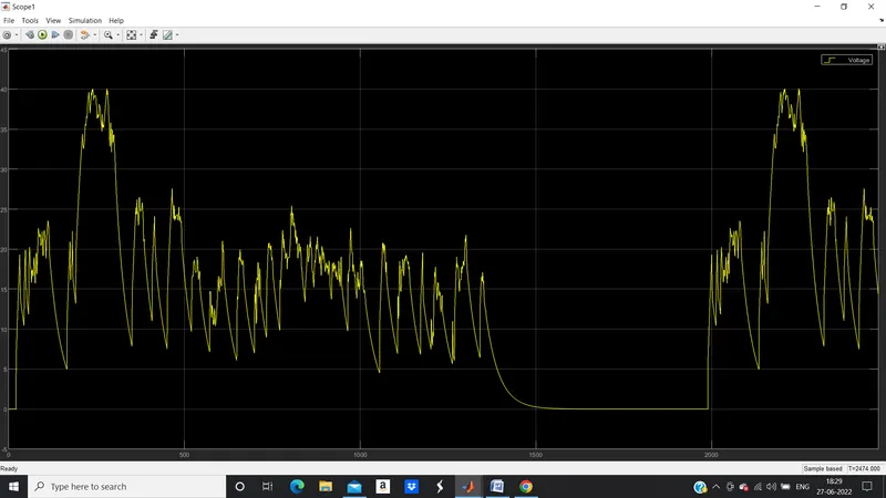
The vehicle is operated as per the battery specifications as mentioned above on the specifications, the battery voltage supplied as the major source is 300 V and the motor used is the DC Motor in the overall operation the efficiency is been measured and as the operation of the cycle is operated at a specified duration of the FTP-75 the same is been experienced.
The overall distance travelled by the vehicle is 5.9 kms in a duration of 2474 seconds.
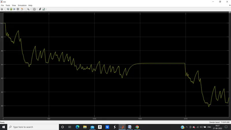
Result of Battery SOC: It is noted that the the Charge of the battery started from 100% at the initial level and during the operation of the vehicle for 2474 seconds using the FTP-75 Drive Cycle which has its peak throttle after the initial range the discharge occured/noted from the battery are until the high throttle was applied and it was been accelerated the battery got dishcharged at 94% and after the acceleration was been released the battery started recharging as the regenerative energy comes into action. The regenerative braking effectively charges the battery by 1% in the same duration where the vehicles acceleration pedal was been taken off and free wheeling.
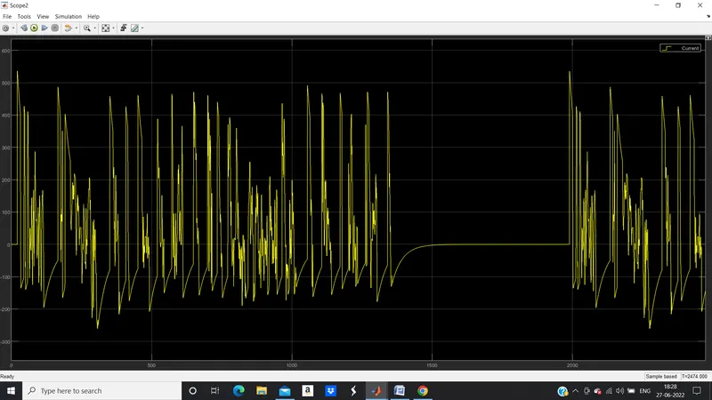
Current taken by the battery:
voltage:
Conclusion: The EV model has been created with necessary block components using the SIMULINK software. The simulation has produced the results of the velocity of the vehicle, current flowing from the battery and state of charge as well as the distance travelled in the simulation time. The EV model was able to follow the commands given byreference velocities from the drive cycle data. The distance travelled by EV model was 5.96 kms and it used FTP-75 drive cycle. The SOC of the battery was discharged efficiently upto 89% from full charge. This model has also included some features like regenerative braking which was evident in the current scope and state of charge scope.