Final Project: Design of an Electric Vehicle
EV BATCH -17
AIM : To create a MATLAB model of an electric car which uses a battery and a DC motor, by choosing suitable blocks from Powertrain block set.
THEORY :
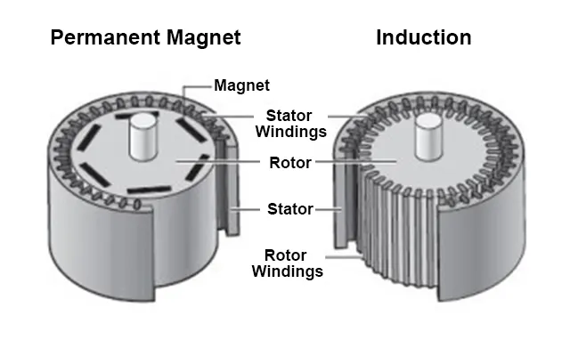
An electric car is a vehicle that is propelled by one or more electric motors, using energy stored in rechargeable battery packs. These are eco-friendly and has higher efficiency compared to ICE cars. An electric vehicle is 69-72% efficient when counted against stored chemical energy and around 59-62% efficient when counted against required energy to recharge. They use electric motors for propulsion. The most common types of motors used are Permanent Magnet Synchronous Motor (PMSM) and three phase induction motor.
The battery packs are recharged using AC/DC charging technologies. AC charging is slow as it has to be converted to DC. Hence for fast charging DC chargers are used. The charging sockets has different standards as shown below,
Block diagram of Electric vehicle which uses a DC motor as shown below,
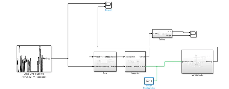
Now let us look at each of the blocks used to create this MATLAB model.
>>Drive cycle source :
For this we have used Drive cycle source block.
The block parameters for this block as shown below
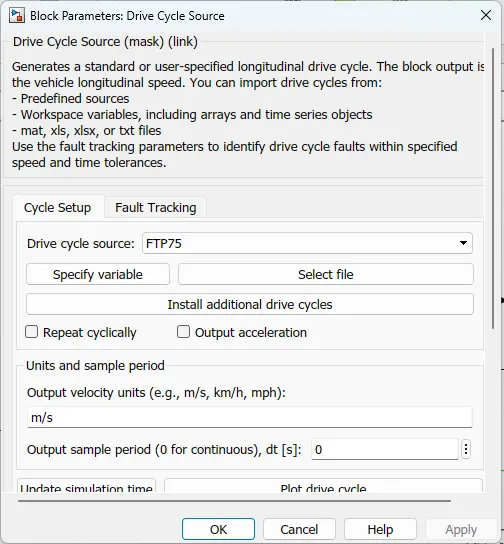
This block will help us in inputting the drive cycle data, whether it is built in or custom made by the user. That is we can use custom made drive cycle data in excel sheet using this block.
For this model we have used FTP 75 drive cycle, which is built-in in this block.
>>Drive cycle :
Longitudinal driver :
This block is used to create a longitudinal speed-tracking controller and it is based on reference and feedback velocities, the block generates normalized acceleration and braking commands that can vary from 0 through 1. We can use this block to model the dynamic response of a driver or to generate the commands necessary to track a longitudinal drive cycle.
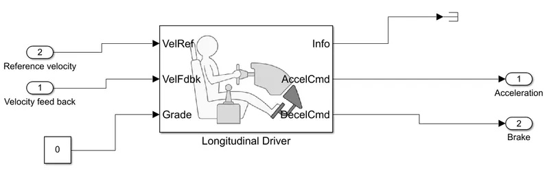
The block parameters is as shown below
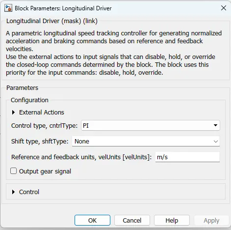
In this longitudanal driver as the parameters are the reference velocity velocity feedback and the grade value is to be zero.Acceleration and brake command and decceleration command is taken on another side.
>>Power control unit subsystem(Controller ) :
This subsystem has the blocks which are used to create the voltage signals to control the motor s input drive cycle data.
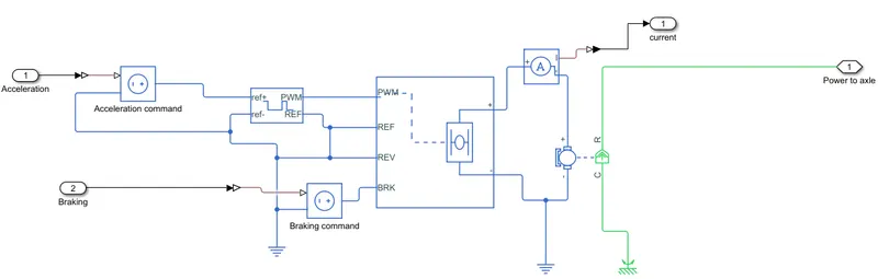
This subsystem is connected to the longitudinal driver block output ports namely acceleration command and deceleration command.
This subsystem will convert this acceleration and deceleration command into voltage signals using two controlled voltage source block, controlled PWM voltage block, a H-bridge and a current sensor.
Controlled voltage source block :
The controlled voltage block name it as acceleration command through the diagram so the block parameters is shown below.
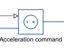
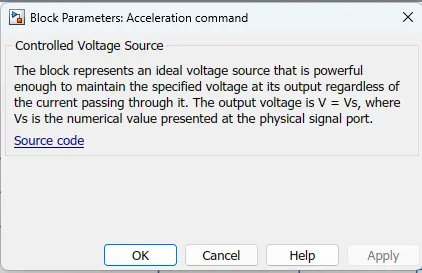
This block is used to maintain the specified voltage as its output regardless of the current flowing through the source.
Controlled PWM voltage block :
The block and its parameters is as shown in below.

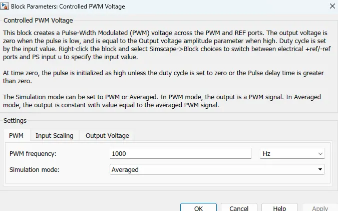
Here in input scaling we can change the values 0 (for input voltage for 0% duty cycle) and 1 (for input voltage for 100% duty cycle).
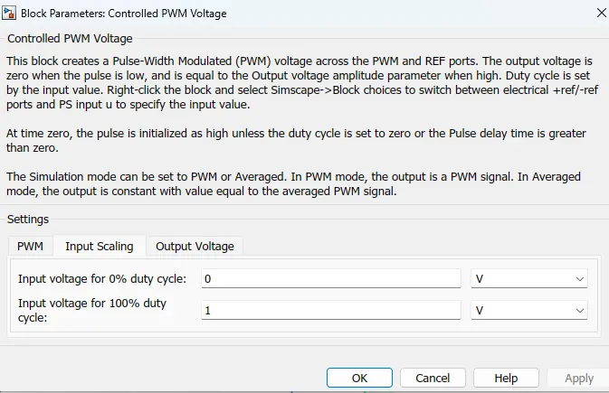
This block is used to create the pulse width modultaed(PWM) voltage, it consits of ref+,ref-,PWM,REF
Electrical input ports :- The block calculates the duty cycle based on the reference voltage across its ref+ and ref- ports .This modeling variant is the default
The value of the output voltage amplitude parameter determines amplitude of the output voltage.
H-bridge block :
This block is used to change the polarity of the voltage applied across the DC MOTOR so as to run the motor in forward and reverse direction as per the input command.
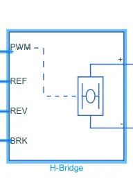
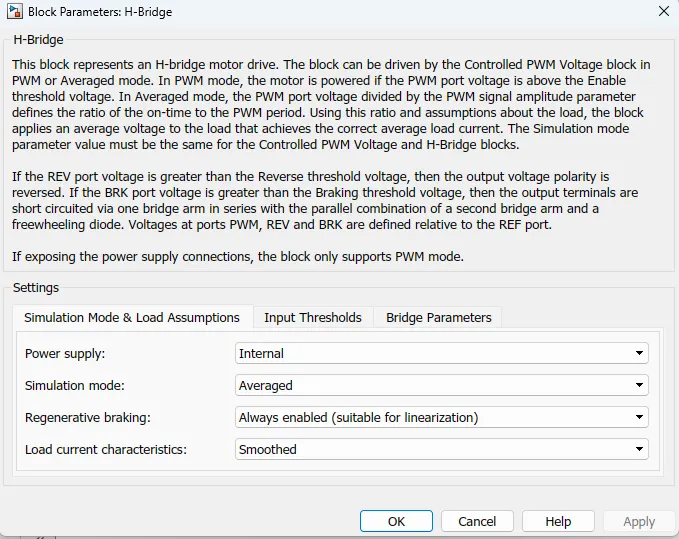
H-bridge block parameters consists of this settings, here we can change the values of simulation model. so finally parameters are power supply as internal simulation model is to be averaged,regenerative braking is to be always enabled for this block diagram and the load current charaacteristics is to be smoothed
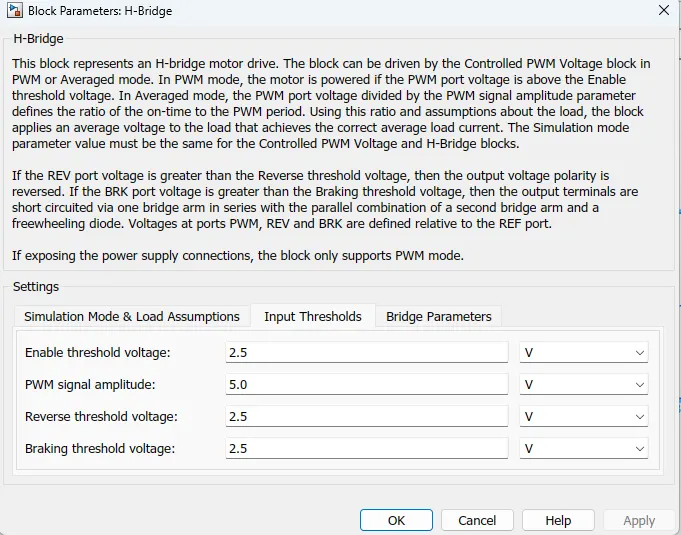
here input tresholds parameters are changed as enable treshold voltage is to be 2.5 PWM signal amplitude is 5 reverse treshold voltage is 2.5 and braking treshold voltage is 2.5
Current sensor block :
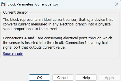
This is used to measure the current flowing through the H-bridge.
The block and its parameters is shown below.

DC motor :
To convert the electrical energy to mechanical energy we use motors.In this electric vehicle model we have used DC motor.This motor can acct as a generator also in case of regenerative braking.
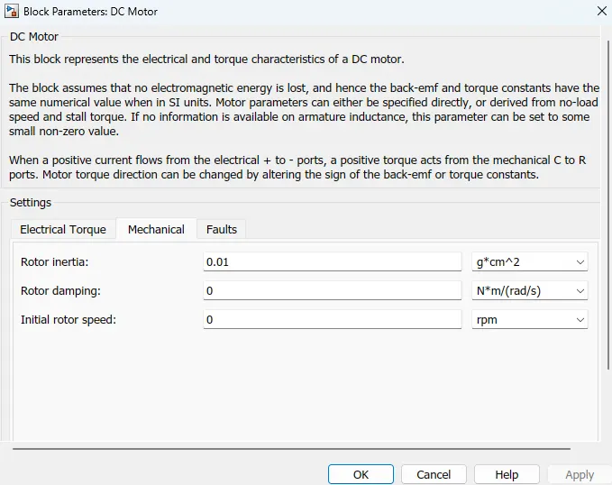
The motor block and its parameters as shown in below.
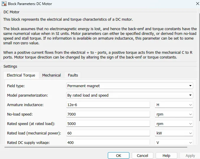
Here in this model we can select the Electrical torque as field type is permenant magnet,and model parameterization by rated load and speed.here we can armature inductance as 12e-6Hat noload speed 7000 rpmand the rated speed(at rated load) is 5000rpm.The rated load (mechanical power)is to 75 kilowatts and the rated dc supply voltage is 400
and the mechanical rotor inertia is 0.01 remaining rotor damping and intial rotor speed is to be zero
>>Battery subsystem :
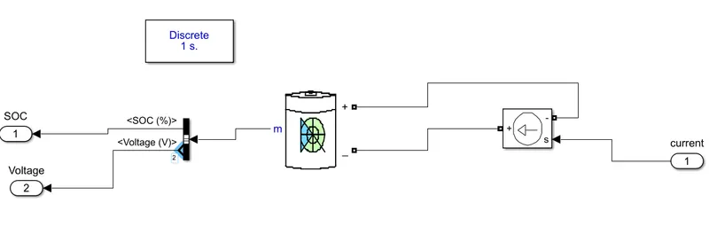
In this subsystem we have a battery block ,a controlled current source block,powergui block is used and a connection port block is used.
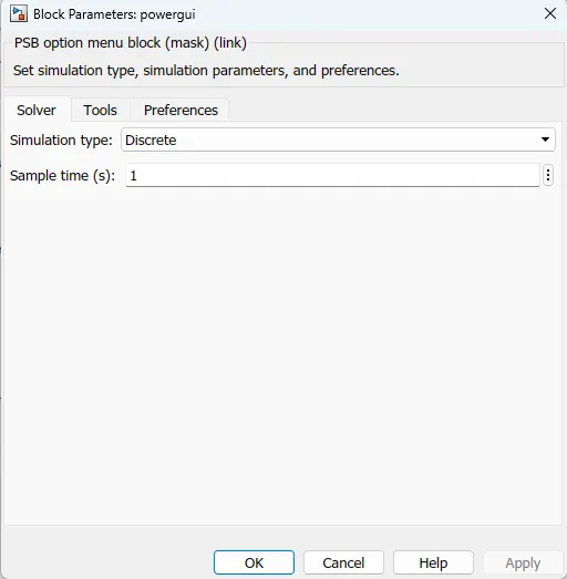
Here we can use powergui block , it can helps to giving continous signal, in this block parameters we can change the discrete simulation type and sample time is to be 1
In this battery subsystem we have one input port is current we can get two output ports voltage and SOC (state of charge).
Battery :
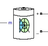
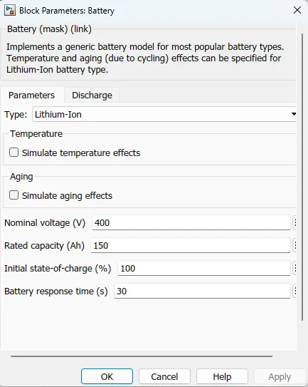
The battery consists of input and output terminal negative and positive ,here we are using battery type is lithium ion,
Here we can change the select parameters,Nominal voltage is 400 voltsand rated capacity 150ah is taken,intial state of charge is 100%and the battery response tinme is taken 30 seconds.
Bus selector :
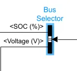
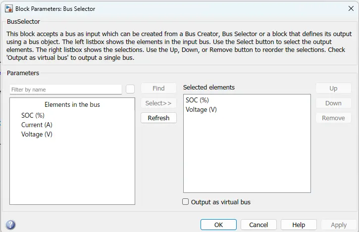
Here we can take the elements are SOC and the voltage and it can consists to execute the output,so output terms are SOC and voltage.
>>Vehicle body subsystem :
This subsystem represents the body of a vehicle .This block diagram for this subsystem is shown below.
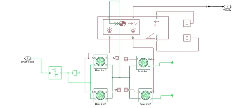
The input to this subsytem is the velocity block it consists the velocity taken to the controller drive.
simple gear :
It represents a fixed-ratio gear or gear box. No inertia or compliance is modeled in this block. You can optionally include gear meshing and viscous bearing losses.Connections B (base) and F (follower) are mechanical rotational conserving ports. Specify the relation between base and follower rotation directions with the Output shaft rotates parameter. Optionally include thermal effects and expose thermal conserving port H by setting Friction model to a temperature-dependent setting.

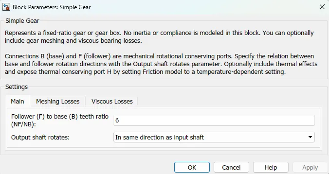
Here also we can change the simple gear Follower to base to teeth ratio (NF/NB) is 6 and the output shaft rotates as in the same direction as input shaft.
Inertia :
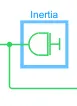
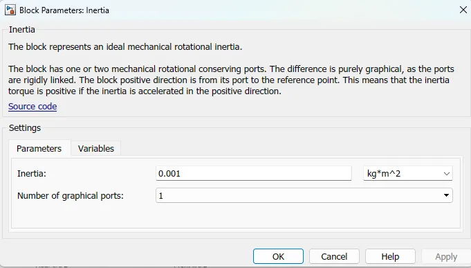
The block represents an ideal mechanical rotational inertia.The block has one or two mechanical rotational conserving ports. The difference is purely graphical, as the ports are rigidly linked. The block positive direction is from its port to the reference point. This means that the inertia torque is positive if the inertia is accelerated in the positive direction.
Magical tire :
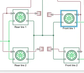
we are using four tyres in this block diagram,two are front tires and the two are back tires.Those tire are represents as magic tire and the terminals are H is hub and s is slip N normal force acting on the tire , A is the mechanical rotational conserving port for the wheel axle. we didnt any change in this block parameters.
Vehicle body :
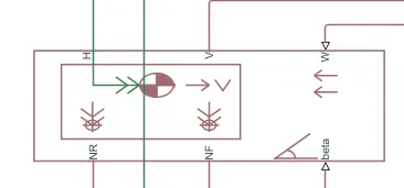
It represents a two-axle vehicle body in longitudinal motion. The block accounts for body mass, aerodynamic drag, road incline, and weight distribution between axles due to acceleration and road profile. The vehicle can have the same or a different number of wheels on each axle. Optionally include pitch and suspension dynamics or additional variable mass and inertia. The vehicle does not move vertically relative to the ground.The resulting traction motion developed by tires should be connected to this port. Connections V, NF, and NR are physical signal output ports for vehicle velocity and front and rear normal wheel forces, respectively. Wheel forces are considered positive if acting downwards. Connections W and beta are physical signal input ports corresponding to headwind speed and road inclination angle, respectively.
In this terms we used the values are default taken,No changes is requires for this terminal,
PS-constant :
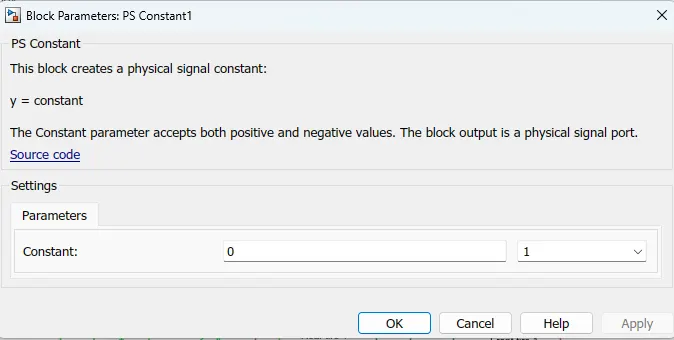
This block creates a physical signal constant and y taken as constant,The Constant parameter accepts both positive and negative values. The block output is a physical signal port.
Here we can change the value of the ps constant from 1 to 0
Scope :

Here we are using 2 scopes and we get 4 values are velocity feedback,reference velocity,voltage and SOC(state of charge).
RESULT :
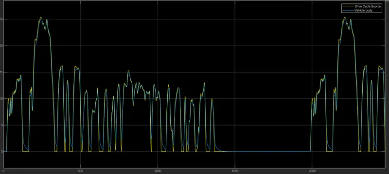
Here the simulation time taken for this block is 2474 sec for using FTP drive cycle and we get the result in the first scope is input vs output velocity graph .This scope has two inputs,one is FTP75 drive cycle and the other one is the velocity feedback.This two is combined using a bus and connection port and to the scope is connected to get this graph.
The resulting graph for this scope is shown below.
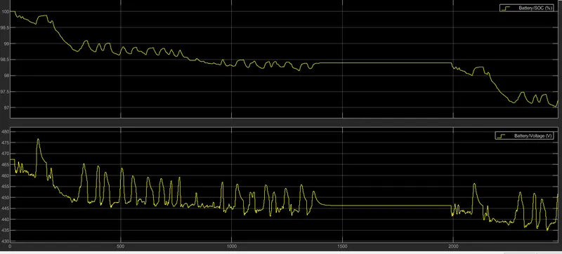
The next scope is used to get the change in soc value with respect to time The input for this scope is taken from current.
Conclusion :
The model was successfully run for simulation under standard FTP75 drive cycle source and we can design an electric vehicle and seen its performances with respect to the voltage and SOC .in this project inputs are drive cycle source as vehicle body and the out put as the battery voltage and the SOC . intially soc is start as 100% after it executes as the 2474 seconds its discharge to 97%and the voltage value is started from 468volts and the driving for 2474seconds then the remaining voltage is to be 451volts .