Final Project: Design of an Electric Vehicle
EV BATCH - 16
Final Project: Design of an Electric Vehicle
Create a MATLAB model of an electric car that uses a battery and a DC motor. Choose suitable blocks from the Powertrain block set. Prepare a report about your model including the following:
Aim: To create a MATLAB model of an electric car that uses a battery and a DC motor and prepare a report about it.
Objectives:
1. System level configurations
2. Model parameters
3. Results
4. Conclusion
Electric Vehicle: An electric vehicle, also called an EV, uses one or more electric motors (traction motors) for propulsion. An electric vehicle may be powered through a collector system by electricity from off-vehicle sources or may be self-contained with a battery, solar panels, or an electric generator to convert fuel to electricity. There are mainly 3 types of EVs:
-
Battery Electric Vehicles (BEVs): Powered solely by an electric battery, with no gas engine parts. Most BEVs are capable of fast charging
-
Plug-in Hybrid Electric Vehicles (PHEVs): Similar to a Hybrid, but with a larger battery and electric motor. Has a gas tank and a charging port
-
Hybrid Electric Vehicles (HEVs): Low-emission vehicles that use an electric motor to assist gas-powered engines. All energy comes from gasoline.
Battery electric vehicle: A battery electric vehicle or BEV is a pure electric vehicle that uses chemical energy stored in rechargeable battery packs. BEVs use electric motors and motor controllers instead of internal combustion engines (ICEs) for propulsion.
Batteries used in a BEV:
- Lithium-ion battery
- NMIH or Nickel Metal Hydride battery
- Lead-Acid battery
Traction motor: A traction motor is an electric motor used for the propulsion of a vehicle, such as locomotives or electric vehicles. The most commonly used traction motors in EVs are:
- DC Series Motor
- Brushless DC Motor
- Permanent Magnet Synchronous Motor (PMSM)
- Three Phase AC Induction Motors
- Switched Reluctance Motors (SRM)
Block diagram of BEV:
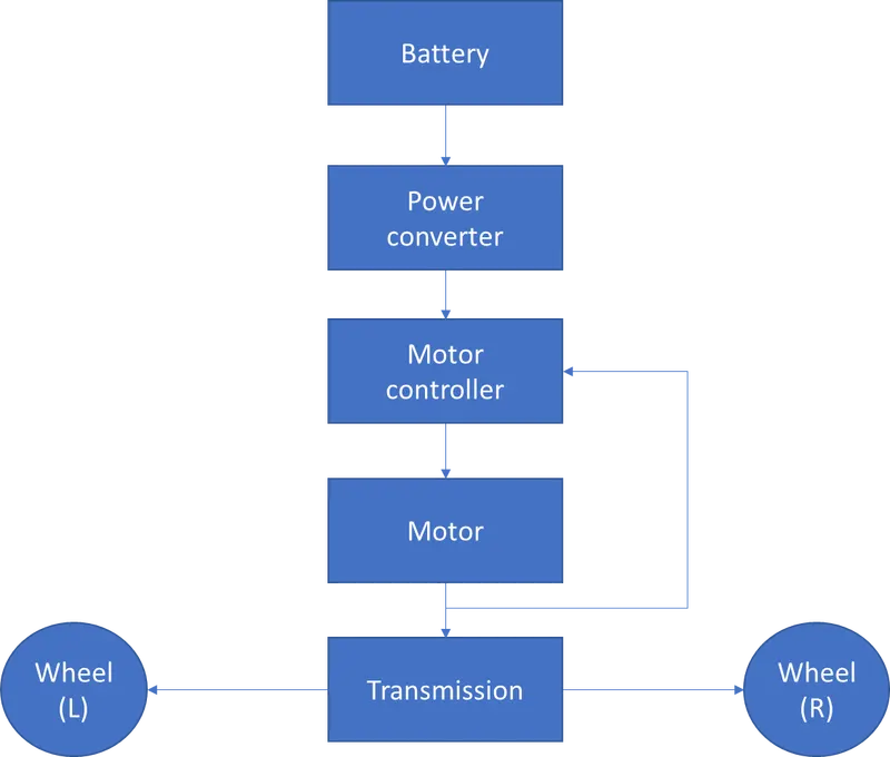
Power supply: AC electricity is sent to the car from the main supply, and the car’s OBC (On-Board Charger) converts the AC to DC, which charges the electric vehicle battery. The OBC limits the speed at which the car battery charges because different electric vehicles have OBCs with different capabilities.
Power electronics: Power electronics are devices that process voltages and currents to deliver power that supports a variety of needs based on the application. The different power electronic devices are:
- AC-to-DC Converters or rectifiers
- DC-to-DC Converters or choppers
- DC-to-AC Converters or inverters
Different power converters used in an Electric vehicle:
- Bidirectional Battery Charger for an Electric Vehicle
- Bidirectional DC-DC Converter
- Integrated Bidirectional Converters
- AC–DC Converter
- Resonant Converter for a Bidirectional EV Charger
- Isolated Bidirectional AC–DC Converter for a DC Distribution System
- Bidirectional T-Type Converter for EV Applications
- Multilevel Two-Quadrant Converter for Regenerative Braking
Vehicle Control unit/Motor controller: The EV control module is a low-voltage control module responsible for most processes relating to the functional aspects of electric vehicles. The EV control module takes a variety of driver inputs and calculates a torque value to be sent to the inverter. This torque value is proportional to the accelerator and brake pedal positions as well as the gearbox setting and is arbitrated via any other vehicle torque demands. Different processes of VCU include:
- Power modes for EV, HEV (start-up, driving, charging, error)
- Torque request acquisition and validation
- Torque Management on HEV and EV (e. g. calculation of driver torque demand, drivability filtering, and torque limitation)
- Vehicle Powertrain Control
- Transmission Gear Control
- Battery Charge (AC & DC)
- Thermal management
- Energy management
- Safety Monitoring unit
Vehicle modeling: Necessity
- In order to be able to estimate the performance of an electric vehicle, it is very important to have a proper model of it.
- The electric vehicle model is very complex as it contains many different components. Each component needs to be modeled properly in order to prevent wrong conclusions.
- The design or rating of each component is a difficult task as the parameters of one component affect the power level of another one.
- There is therefore a risk that one component is rated inappropriately which may make the vehicle unnecessarily expensive or inefficient. Therefore System-level configurations are necessary.
Simulink model of Electric vehicle:
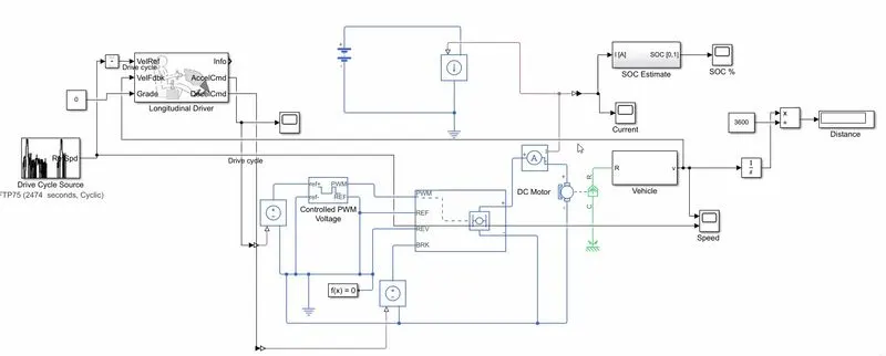
Simulink blocks used:
- Drive cycle source
- Longitudinal driver
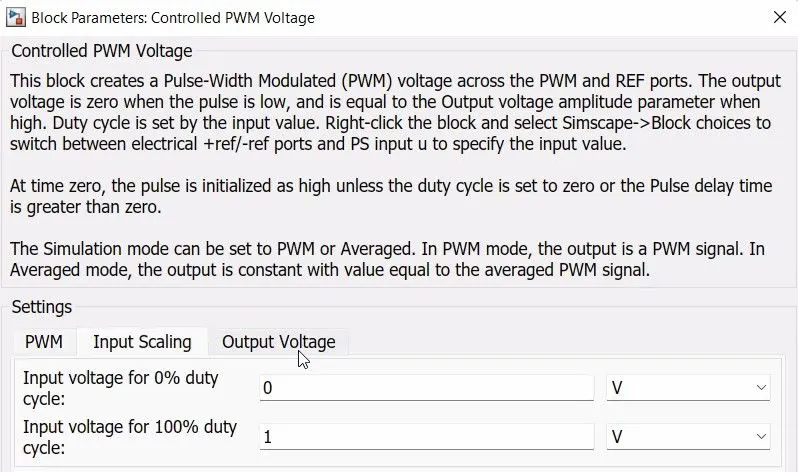
- Controlled PWM voltage
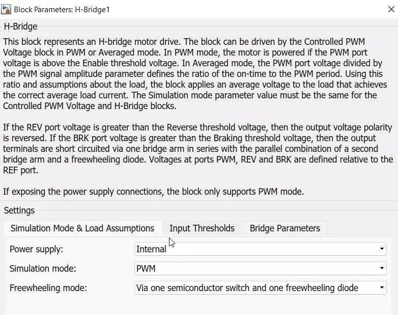
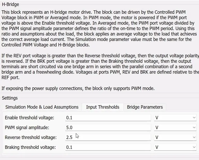
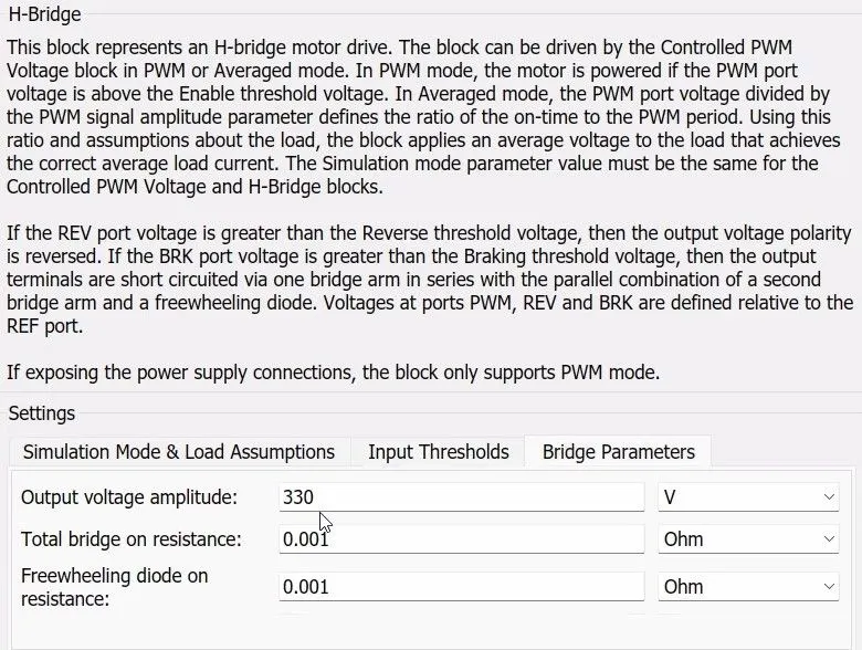
- H bridge
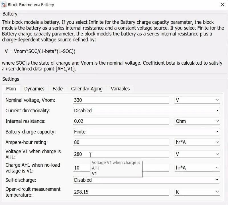
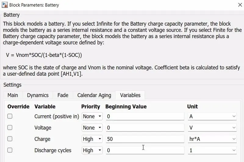
- Battery
- Vehicle body
- DC motor
- Simple gear
- Side shaft
- Tire (magic formula)
- Rate transition
- Discrete integrator
- Constant
- Product
- Constant current sensor
- Current sensor
- Solver configuration
- Electrical reference
- Rotational reference
- Gain
- Connection ports
- Go to
- Display
- Scope
- PS -Simulink, Simulink-PS converters
Model Input Parameters:
- Longitudinal driver:
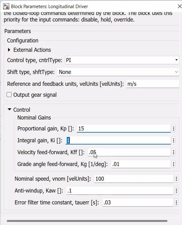
- Controlled PWM voltage: This block
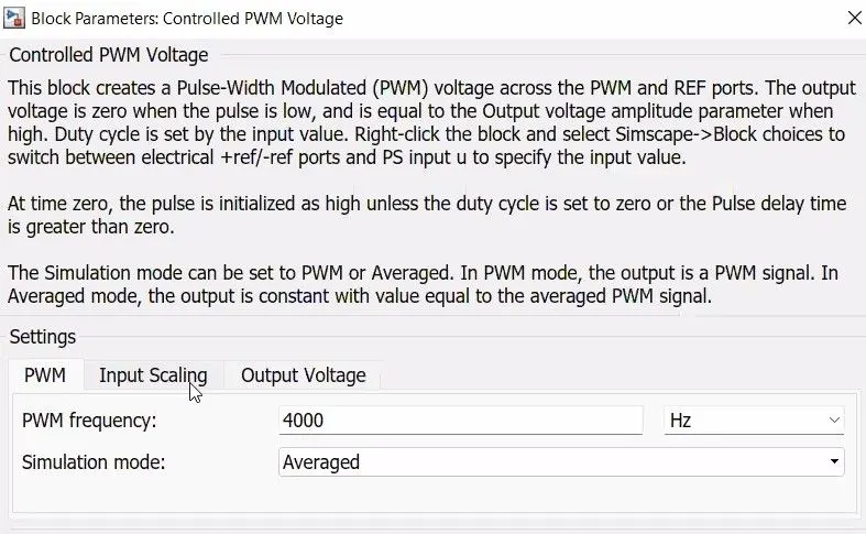
- H-Bridge
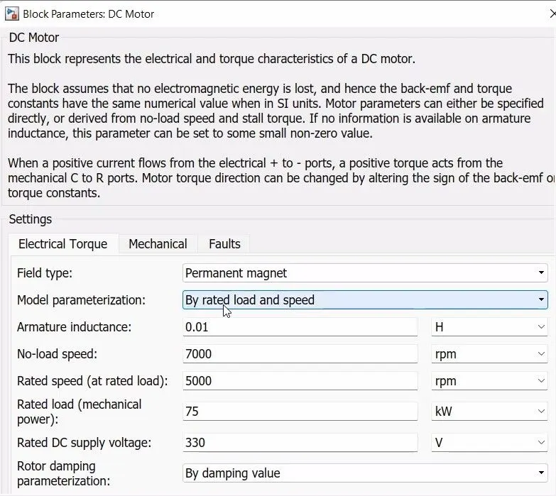
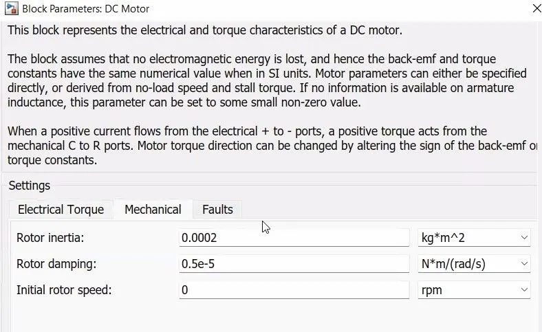
- DC motor
- Battery
- Simple gear
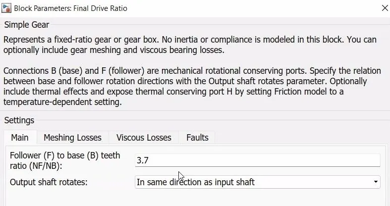
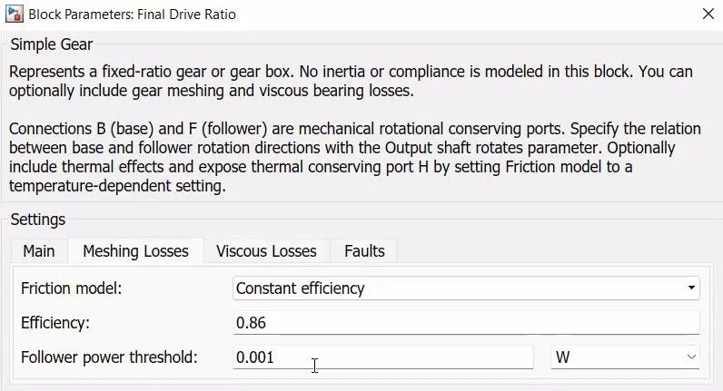
- Tire
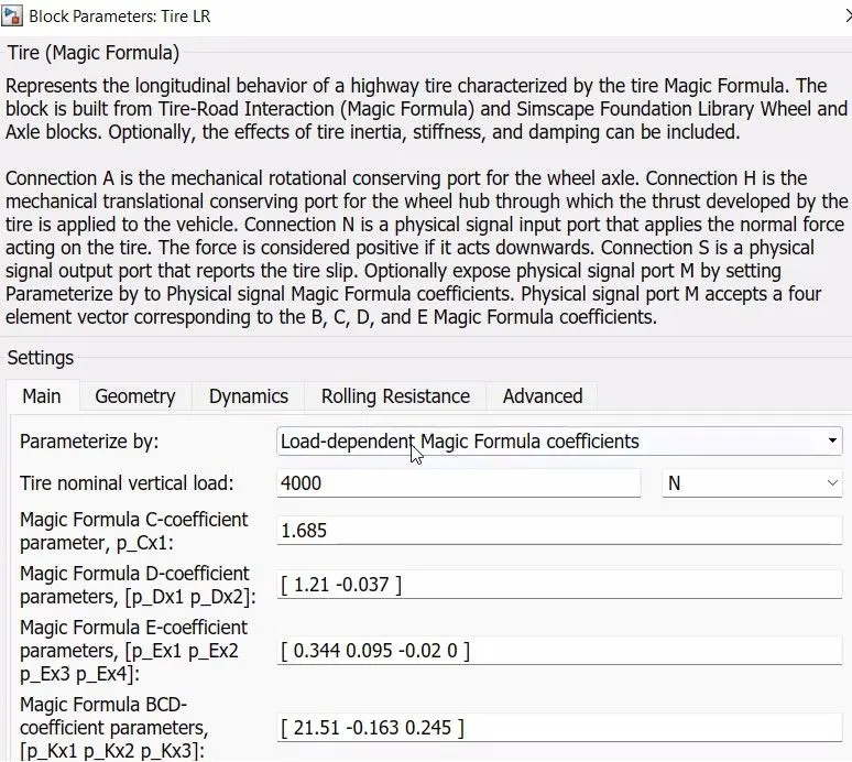
- Rate transition
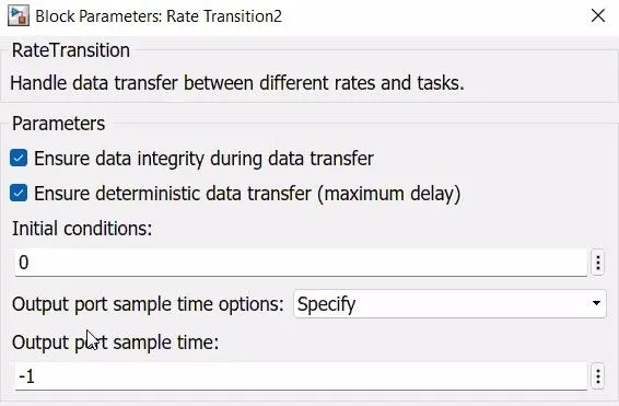
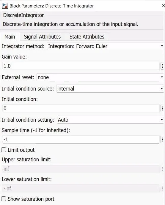
- Discrete integrator
Results:
Output plots:
This plot represents the SOC% which is the battery capacity left at the end of the drive cycle.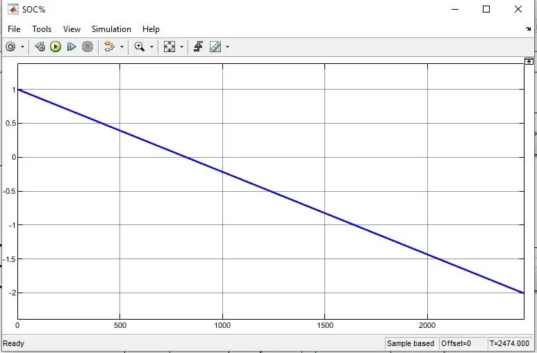
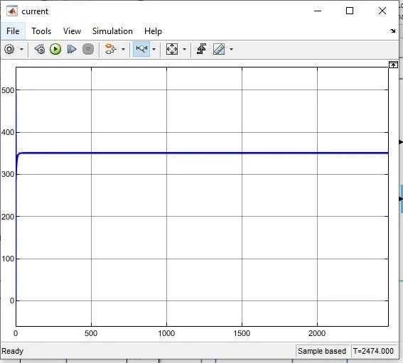
Current:
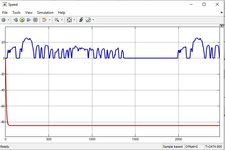
Speed:
Conclusion:
The Vehicle modeling is done by using the Simulink software. The drive cycle used is FTP 75. By referring to the plots of SOC%, current used, and Speed, we can conclude that at higher speeds the current used by the motor is higher and SOC reduces at a faster rate. At constant normal speed, the current used is also nearly constant.