Final Project: Design of an Electric Vehicle
Create a MATLAB model of electric car which uses a battery and a DC motor. Choose suitable blocks from Powertrain block set. Prepare a report about your model including following:
Objectives:
1. System level configurations
2. Model parameters
3. Results
4. Conclusion
Electric vechile- An electric vehicle (EV) is one that operates on an electric motor, instead of an internal-combustion engine that generates power by burning a mix of fuel and gases.
Electric Vehicles – Environmental Advantages
Electric cars (or electric vehicles, EVs) have several environmental benefits compared to conventional internal combustion engine cars.
- Have the potential to reduce greenhouse gas emissions
- Reduce dependence on petroleum
- Reduce health effects from air pollution
- Reduce dependence on petroleum
- They produce little or no tailpipe emissions
Electrical Vehicles – Better Energy Efficiency
- Internal Combustion engines will consume fuel even when the vehicle is stationary, whereas in electrical vehicles, the energy is not consumed when it is stationary.
- Electrical Vehicles ‘tank-to-wheels’ efficiency is about a factor of 3 higher than internal combustion engine vehicles
Electric Vehicles – Mechanical Advantages
- They can be finely controlled and provide high torque from rest, unlike internal combustion engines, and do not need multiple gears to match power curves. Hence it removes the requirement for gearboxes and torque converters.
- Lesser vibration
- Lesser noise
- Electric motors are mechanically very simple and often achieve 90% energy conversion efficiency over the full range of speeds and power output and can be precisely controlled.
Plug-in Electric Vehicle (PEV)
A plug-in electric vehicle (PEV) is any motor vehicle that can be recharged from any external source of electricity, such as wall sockets, and the electricity stored in the Rechargeable battery packs drives.
Plug-in Electric Vehicles can be further categorized into
- Plug-in Hybrid Electric vehicles, (PHEVs)
- Battery electric vehicles (BEVs)
Plug-in Hybrid Electric Vehicles (PHEV)
- A plug-in hybrid electric vehicle (PHEV) is a hybrid electric vehicle whose battery can be recharged by plugging it into an external source of electric power, as well as by its on-board engine and generator.
- Most PHEVs are passenger cars, but there are also PHEV versions of commercial vehicles and vans, military vehicles, utility trucks, trains, motorcycles, buses and mopeds.
Battery Electric Vehicles
- A battery electric vehicle (BEV), pure electric vehicle, only-electric vehicle or all-electric vehicle is a type of electric vehicle (EV) that exclusively uses chemical energy stored in rechargeable battery packs, with no secondary source of propulsion.
- Battery Electric Vehicles (BEV) thus have no internal combustion engine, fuel cell, or fuel tank.
- Some of the broad categories of vehicles that come under this category are trucks, cars,buses, motorcycles, bicycles, forklift etc.
BLOCK DIAGRAM OF ELECTRIC VECHILE -
we design our electric vechile according to block diagram-
let me explain the block digram-
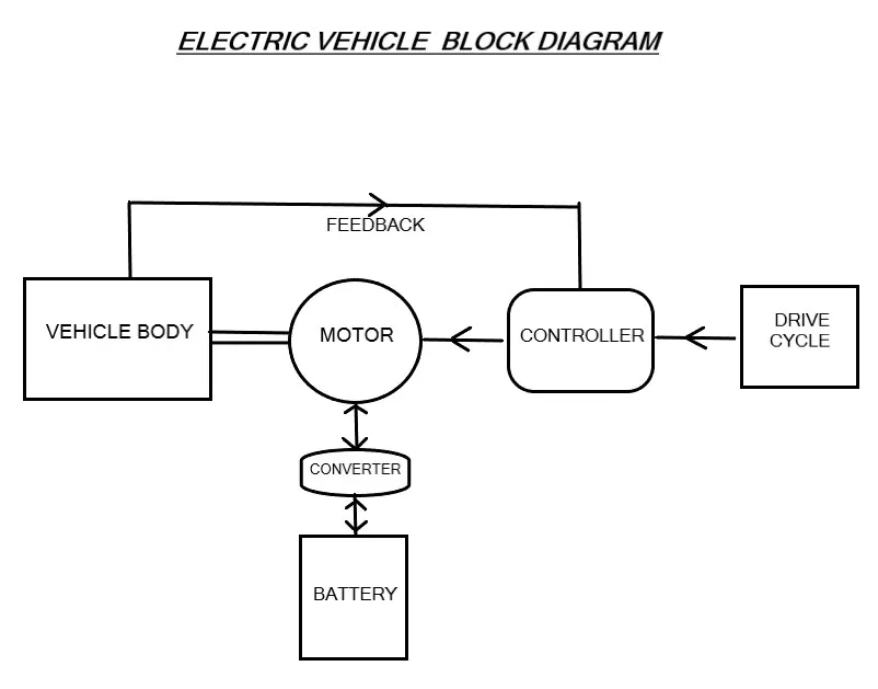
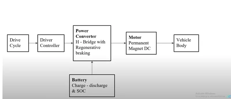
first we have vehcile body and then take a motor (permanent magnet dc) and we will connect motor shaft to the axel of the vechile body and before connecting the battery direct to the motor we required motor controller (to change the speed of the motor ) , controller is nothing but a H bridge with regenrative braking feature so the battery supply power to power converter, and power converter change the voltage applied to the motor and that will actually change the speed of the motor. for run your vechile at what speed that u want we have to use throttle and brake pedals to give input this nothing but a Drive cycle.we have to give drive cycle to run our vehcile at speed that we want,there is driver controller which track actual speed of the vehicle and which will match with the given input.
Matlab Model-
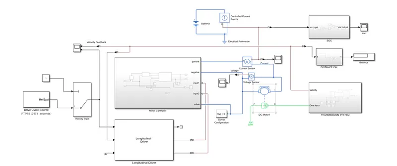
System level configurations-
VECHILE BODy & TRANSMISSION SYSTEM-
vechile body-
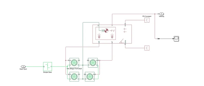
Represents a two-axle vehicle body in longitudinal motion. The block accounts for body mass, aerodynamic drag, road incline, and weight distribution between axles due to acceleration and road profile. The vehicle can have the same or a different number of wheels on each axle. Optionally include pitch and suspension dynamics or additional variable mass and inertia. The vehicle does not move vertically relative to the ground.
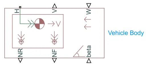
Connection H is the mechanical translational conserving port associated with the horizontal motion of the vehicle body. The resulting traction motion developed by tires should be connected to this port. Connections V, NF, and NR are physical signal output ports for vehicle velocity and front and rear normal wheel forces, respectively. Wheel forces are considered positive if acting downwards. Connections W and beta are physical signal input ports corresponding to headwind speed and road inclination angle, respectively. If variable mass is modeled, the physical signal input ports CG and M are exposed. CG accepts a two- element vector representing the x and y distance offsets from vehicle CG to additional load mass CG. M represents the additional mass. If both variable mass and pitch dynamics are included, the physical signal port J accepts the inertia of the additional mass about its own CG.
tires
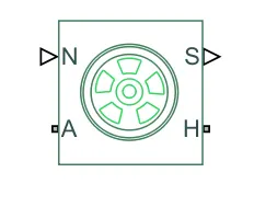
Represents the longitudinal behavior of a highway tire characterized by the tire Magic Formula. The block is built from Tire-Road Interaction (Magic Formula) and Simscape Foundation Library Wheel and Axle blocks. Optionally, the effects of tire inertia, stiffness, and damping can be included.
Connection A is the mechanical rotational conserving port for the wheel axle. Connection H is the mechanical translational conserving port for the wheel hub through which the thrust developed by the tire is applied to the vehicle. Connection N is a physical signal input port that applies the normal force acting on the tire. The force is considered positive if it acts downwards. Connection S is a physical signal output port that reports the tire slip. Optionally expose physical signal port M by setting Parameterize by to Physical signal Magic Formula coefficients. Physical signal port M accepts a four element vector corresponding to the B, C, D, and E Magic Formula coefficients.
simple gear
Represents a fixed-ratio gear or gear box. No inertia or compliance is modeled in this block. You can optionally include gear meshing, backlash, and viscous bearing losses.
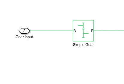
Connections B (base) and F (follower) are mechanical rotational conserving ports. Specify the relation between base and follower rotation directions with the Output shaft rotates parameter. Optionally include thermal effects and expose thermal conserving port H by setting Friction model to a temperature-dependent setting.
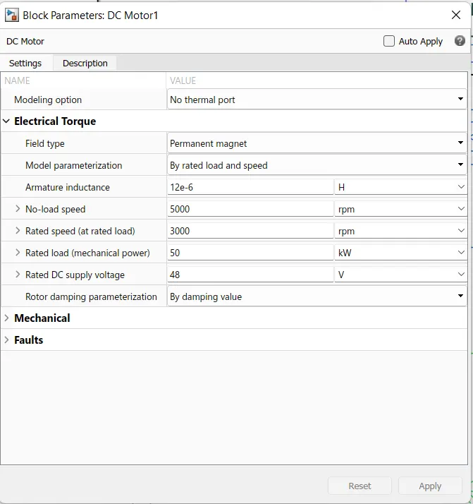
DC MOTOR -
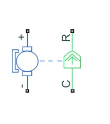
This block represents the electrical and torque characteristics of a DC motor.
The block assumes that no electromagnetic energy is lost, and hence the back-emf and torque constants have the same numerical value when in SI units. Motor parameters can either be specified directly, or derived from no-load speed and stall torque. If no information is available on armature inductance, this parameter can be set to some small non-zero value.
When a positive current flows from the electrical + to - ports, a positive torque acts from the mechanical C to R ports. Motor torque direction can be changed by altering the sign of the back-emf or torque constants.
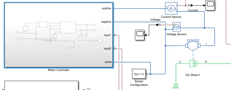
then we connect the motor with power controller block
power controller subsystem-
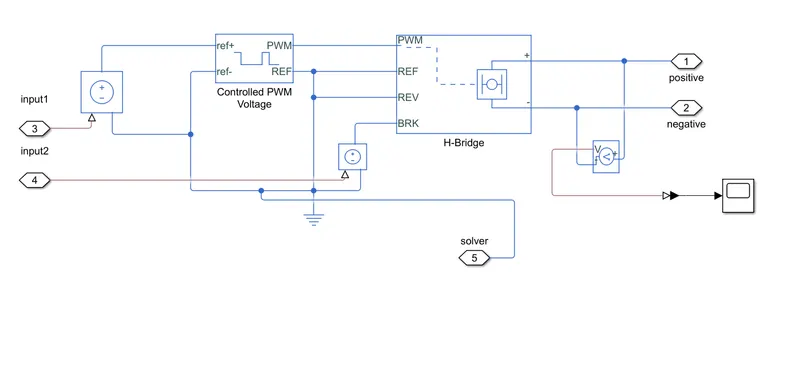
here we use h- Bridge If you’ve done much with motor control, you’ve probably heard of H-bridges. But what exactly is an H-bridge?
As it turns out, an H-bridge is a super simple circuit in theory:
An H-bridge is built of four switches that control the flow of current to a load. In the image above, the load is the M connecting the two sets of switches. Using one current source, you can drive current in two directions by closing two switches.
If Switch 1 and 4 are closed, then the current will flow from the left to right on this image:
If you close switch 1 and switch 4, the current will flow from the source, through switch 1, and then through the load, then through switch 4, and then back to the load.
In the image above, the circuit has Switch 2 and switch 3 closed. This will cause the current to flow from the source, through switch 3, and then through the load, then through switch 2, then back to the load.
One thing you have to be very cautious about when working with H-bridges is to not create a short circuit. If you create a short circuit, that’s a sure way to burn out your H-bridge. I may have burned out my very first H-bridge at Digilent.
If you drive current and close two switches in series, for example, switch 3 and 4 in the image below, you will cause a short and burn out the H-bridge.
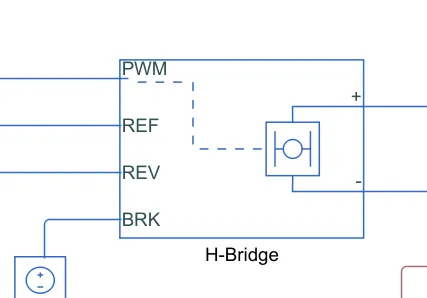
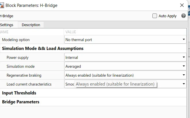
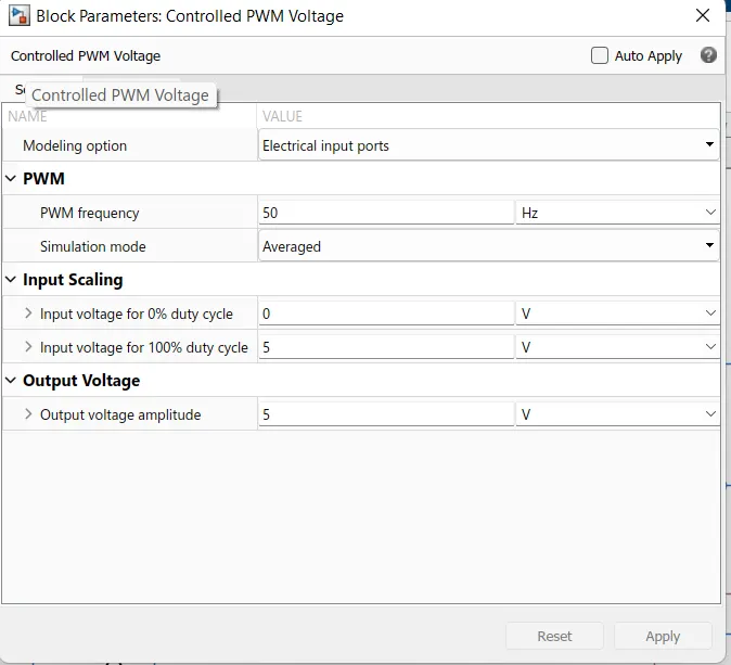
controlled PWM voltage -
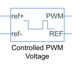
This block creates a Pulse-Width Modulated (PWM) voltage across the PWM and REF ports. The output voltage is zero when the pulse is low, and is equal to the Output voltage amplitude parameter when high. Duty cycle is set by the input value.At time zero, the pulse is initialized as high unless the duty cycle is set to zero or the Pulse delay time is greater than zero.
The Simulation mode can be set to PWM or Averaged. In PWM mode, the output is a PWM signal. In Averaged mode, the output is constant with value equal to the averaged PWM signal.
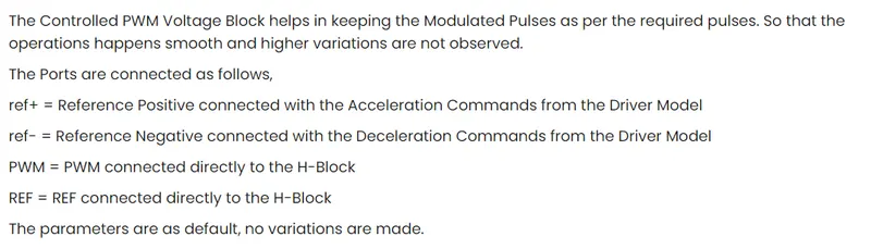
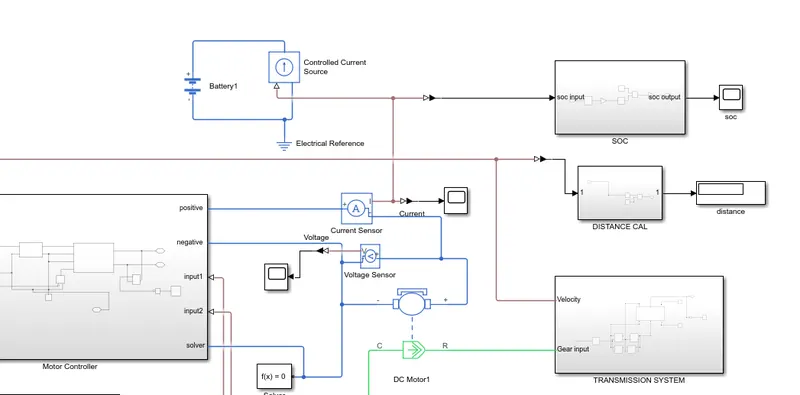
the power controller block is connect with battery and batterySOC part using current sensor block..
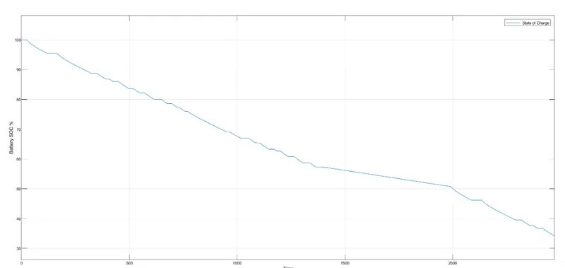
Battery SOC-
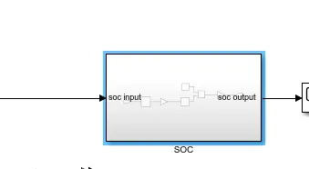
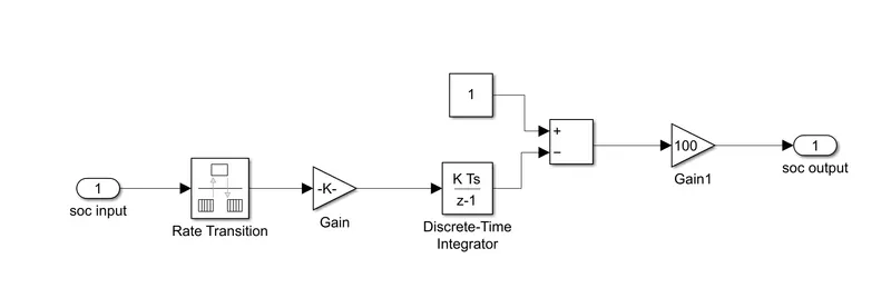
SOC is the percentage or level of batery presents after certaiin travel or consumption of battery or consumption of battery by the vechile, to design vechile battery charge or soc is calculatedd by the giving it to the rate transition and then to gain where 1/( nominal battery capacity ) then to a deiscrete time integrator and it will get minus from the 1 as it is considered a100% of battery and it is multiplied with 100 to get percentage of battery present
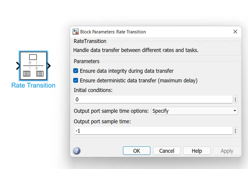
the majority of blocks are simscape block where physical to simulink converter is used to convert the physical signal from simscape block to simulink signal
Longitudnal driver-
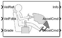
The Longitudinal Driver block implements a longitudinal speed-tracking controller. Based on reference and feedback velocities, the block generates normalized acceleration and braking commands that can vary from 0 through 1. You can use the block to model the dynamic response of a driver or to generate the commands necessary to track a longitudinal drive cycle.
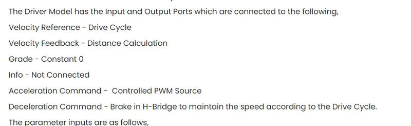
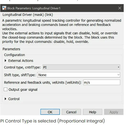
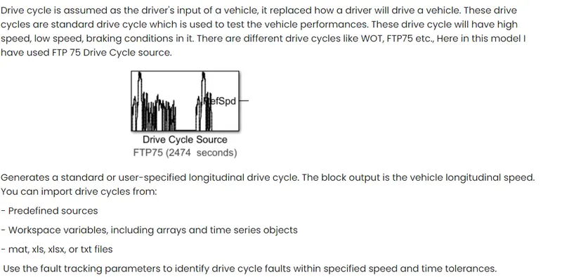
the main system of our electric vehicle is deive cycle we connect our driver controller with the drive cycle
DRIVE CYCLE-
Results-
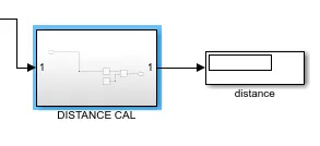
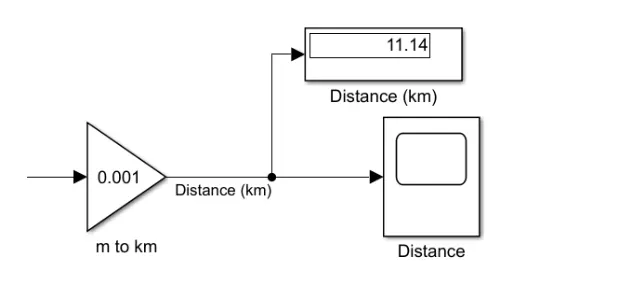
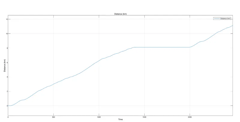
DISTANCE-
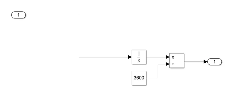
to calculate distance -
output-

SOC estimation- 
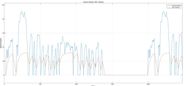
SPEED TRAVELLED-
The speed travelled by the vechile is shown by orange line and actual reference given drive cycle is in blue line.

NOTE-
we take several basics block to do connection between major blocks like
- ps-simulink convertor or vice-versa
- current sensor block
- voltage seensor block
- scope block
- constant block
- ps constant block
- display block
- multiport switch
- solver configuration
- electrical refrence
- mechanical rotational refrence
- battery
- gain block
etc
