Final Project: Design of an Electric Vehicle
AIM:Electric vehicle with matlab model
To model and simulate electric vehicle with simulink
An electric vehicle (EV) is a vehicle that uses one or more electric motors for propulsion. It can be powered by a collector system, with electricity from extravehicular sources, or it can be powered autonomously by a battery (sometimes charged by solar panels, or by converting fuel to electricity using fuel cells or a generator). EVs include, but are not limited to, road and rail vehicles, surface and underwater vessels, electric aircraft and electric spacecraft.
EVs first came into existence in the mid-19th century, when electricity was among the preferred methods for motor vehicle propulsion, providing a level of comfort and ease of operation that could not be achieved by the gasoline cars of the time. Internal combustion engines were the dominant propulsion method for cars and trucks for about 100 years, but electric power remained commonplace in other vehicle types, such as trains and smaller vehicles of all types.
Commonly, the term EV is used to refer to an electric car. In the 21st century, EVs have seen a resurgence due to technological developments, and an increased focus on renewable energy and the potential reduction of transportation's impact on climate change and other environmental issues. Project Drawdown describes electric vehicles as one of the 100 best contemporary solutions for addressing climate change.
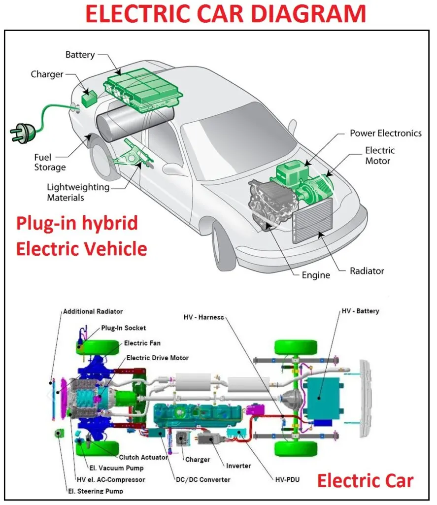
Block diagram of electric vehicle
Vehicle Body Parameters:
- Vehicle body mass, Centre of gravity distance values and aerodynamic drag
variables are modified. Pitch dynamics are kept ON with other variable values as default values.
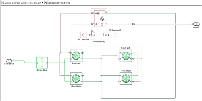
1.1Tire:
The vehicle is assumed to be front axle is driven (4 wheels- 2 on each axle).
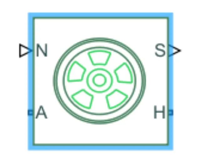
The wheels are modelled using simple Tire (Magic formula) Simulink blocks.
The block can model tire dynamics under constant or variable contact surface
conditions.
- Input Port:
N=Normal force acting on the tire, positive when force is acting downwards/towards the contact surface.
- Output Port:
S=Slip value is relative to tire and surface of contact.
- Conserving Ports:
H=represents wheel hub which transmits thrust generated by the wheel to the body of the vehicle.
A=represents the axle on which the tires are mounted.
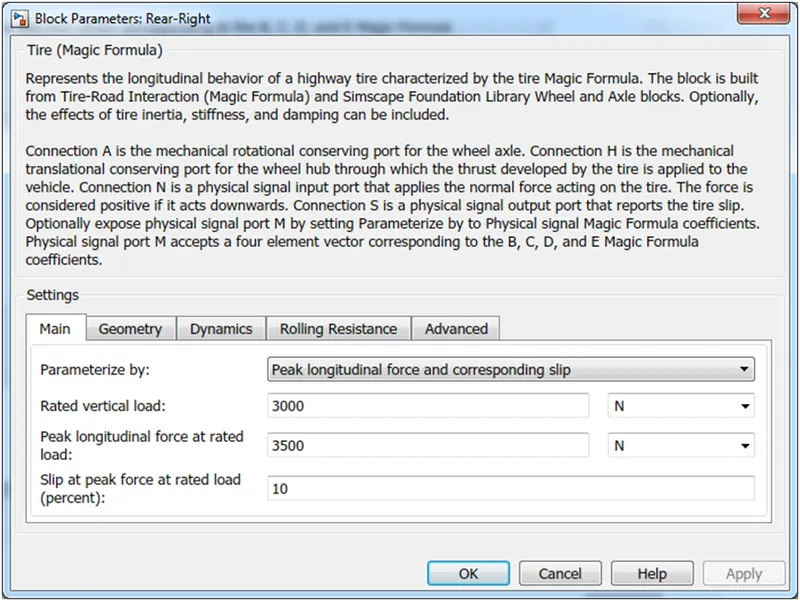
- The tires are parameterized by Peak longitudinal force and corresponding slip
- The other block parameters such as rated vertical load, peak longitudinal force at rated load and slip at peak force at rated load - are kept with their default values.
1.2 Gear:
A simple gear block is used to connect the motor to the rear axle of the vehicle.
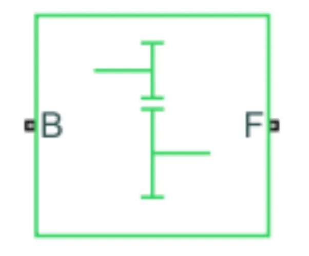
It represents the gearbox that connects the input shaft to the base gear and output from the follower gear.
Conserving Ports:
B=port associated with an input shaft (motor shaft)
F=port associated with the output shaft (axle/ differential)
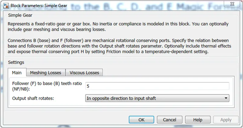
Simple Gear Parameters:
Gear ratio and output direction are modified. Meshing loss is kept constant and gear is having a constant efficiency throughout the simulation.
Viscous losses and faults are kept at default conditions
1.3 Vehicle Body:-
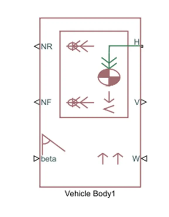
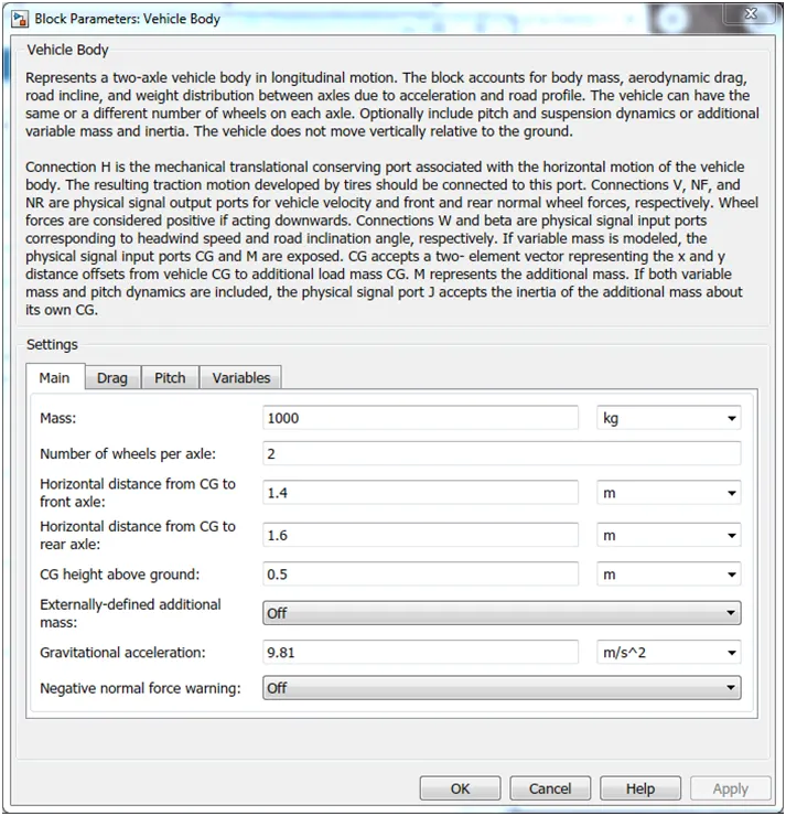
- This block basically represents a two-axle vehicle body in longitudinal motion. The block accounts for - body mass, aerodynamic drag, road incline, weight distribution between axles due to acceleration road profile.
- Here, connection H is the mechanical translational conserving port hub.
- NF & NR correspond to the output ports for normal reaction forces on the front axle and rear axle wheels respectively.
- Connection V represents the actual output translational velocity of the vehicle.
- beta is the road inclination angle & W corresponds to the headwind speed (headwind direction opposite to that of the vehicle).
- The gross weight is given to be 1000 kg
- Power and Motor Controlled Subsystem:-
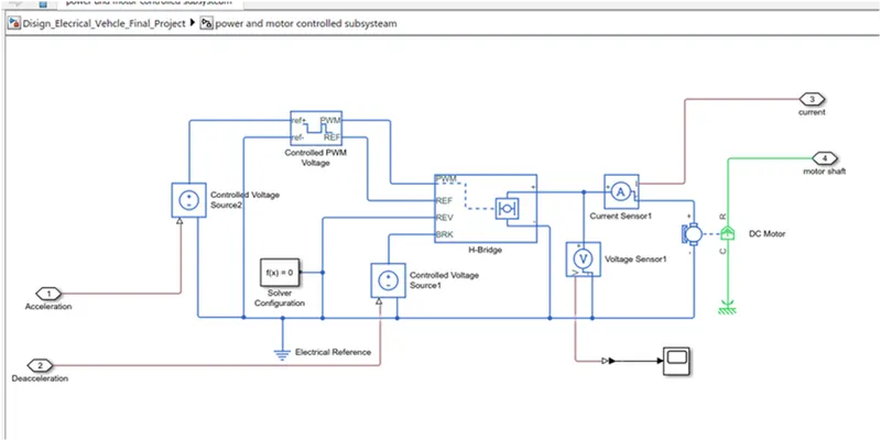
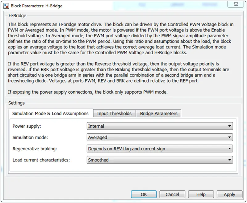
2.1 H-Bridge:-
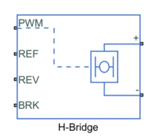
The H-Bridge helps in controlling the power that is input according to the requirement. The output provided is converted voltage as per the controlled parameters.
2.2 D.C Motor:-
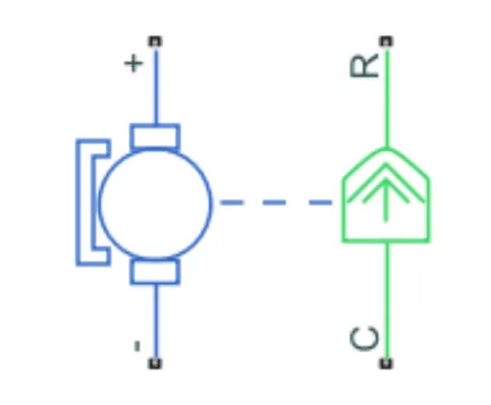
This is the DC Motor which would give rotational power to the wheels and become the sole power generation source.
The DC Motors terminals are connected as mentioned below.
+ =Electrical signal to the motor Positive Terminal
- =Electrical signal to the motor Negative Terminal
R=Casing of the Motor connected with the Mechanical Rotational Reference Block
C=Rotor Case connected to the Mechanical Rotational reference
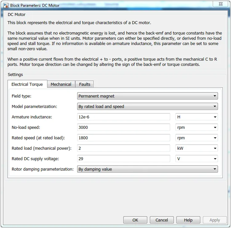
The parameter considered is, The Armature inductance is as default, varied the changes in the No-Load Speed 3000 rpm, the rated speed 1800 rpm, the Rated Load at 2kW, and the Rated DC Supply Voltage 29 V. All other parameters are as default.
2.3 Controlled PWM Voltage:
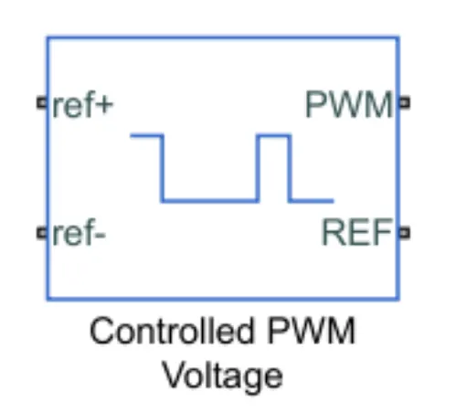
The Controlled PWM Voltage Block helps in keeping the Modulated Pulses as per the required pulses. So that the operations happen smooth and higher variations are not observed.
The Ports are connected as follows.
PWM=PWM connected directly to the H-Block
REF=REF connected directly to the H-Block
ref+ = Reference Positive connected with Driver Model ith the Acceleration Commands from the
ref- =Reference Negative connected with the Deceleration Commands from the Driver Model
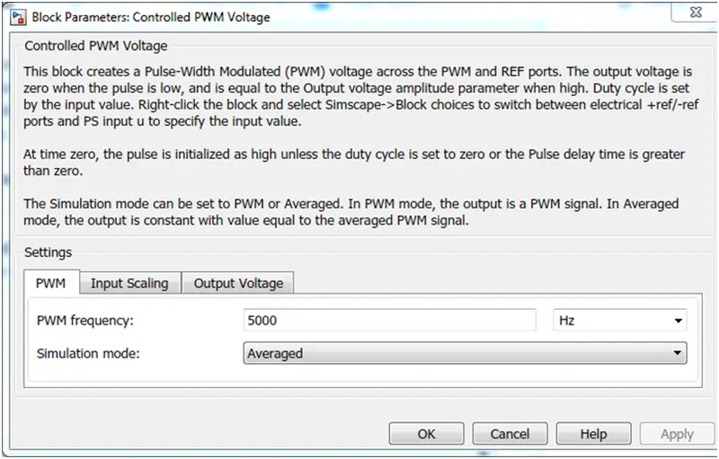
Note: The parameters are set as default.
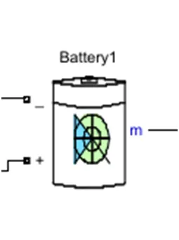
The process of assembling lithium battery cells into a group is called pack, which can be a single battery or a series parallel battery module.
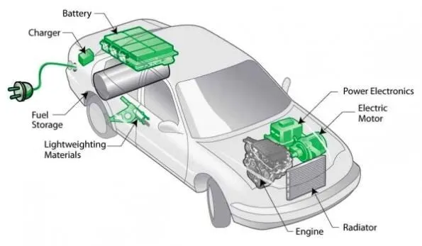
Pack consists of battery pack, bus bar, soft connection, protection board, outer package, output (including connector), highland barley paper, plastic cell holder and other auxiliary materials.
Features of pack
1. Pack of battery pack requires high consistency of battery (capacity, internal resistance, voltage, discharge curve, life).
2. The cycle life of battery pack is lower than that of single battery.
3. Using under limited conditions (including charging, discharging current, charging mode, temperature, etc.).
4. The voltage and capacity of lithium battery pack have been greatly improved after forming, so it must be protected and monitored for charge balance, temperature, voltage and overcurrent.
5. The battery pack must meet the voltage and capacity requirements required by the design.
Pack method
1. Series parallel composition:
The battery is composed of single battery through parallel series connection.
When the capacity is increased in parallel, the voltage does not change.
After the series connection, the voltage multiplies and the capacity does not change.
For example, 3.6v/10ah battery is composed of a single N18650 / 2Ah through 5.
Parallel before series: due to the difference of internal resistance and uneven heat dissipation, parallel will affect the cycle life of battery.
However, the failure of a single battery automatically exits, in addition to capacity reduction, which does not affect the use of parallel, parallel technology is relatively strict.
When a unit battery in parallel is short circuited, the current of parallel circuit is very large, which is usually avoided by fuse protection technology.
Series before parallel:
According to the capacity of the whole battery, series connection is carried out first, for example, the capacity of the whole battery is 1 / 3, and then parallel connection is carried out to reduce the failure probability of large capacity battery.
2. Requirements for electric core:
Select corresponding electric core according to the design requirements.
The parallel and series batteries shall have the same type and model, and the difference in capacity, internal resistance and voltage value shall not be greater than 2%.
In general, the capacity loss of the battery is 2% - 5% when it is combined in series and parallel.
The more the number of batteries, the more the capacity loss.
No matter it is a soft packed battery or a cylindrical battery, it needs to be combined in multiple strings. If the consistency is poor, the battery capacity will be affected.
The battery with the lowest capacity in a group determines the capacity of the whole group of batteries.
High current discharge performance is required.
The starting current of the motor is three times of the normal working current, and the power performance of the motor can be improved only when the large current is discharged.
Good heat dissipation of battery is required.
The number of batteries is large, and the temperature rise of the batteries inside the battery box is not easy to disperse, resulting in uneven temperature and different discharge characteristics among the batteries, resulting in long-term degradation of battery performance. High level of production technology.
The battery shall be able to withstand the vibration impact of bumpy road.
It has a high demand for production technology, especially spot welding technology.
Test shall be conducted after welding to prevent faulty welding and desoldering.
Others
1. Cylindrical battery pack assembly line machine is suitable for all kinds of cylindrical battery pack makingaccording to customer's requirement.
2. Machine can be chosen according to customer's cell productivity.
3. Economic and high-efficiency.
Lead Acid Batteries and Nickel Metal Hydride Batteries
Both lead acid batteries and nickel metal hydride (NiMH) batteries are mature battery technologies. These types of batteries were originally used in early electric vehicles such as General Motor's EV1. However, they are now considered to be obsolete with regards to their uses as the main source of energy storage in BEVs. Lead acid batteries have seen used in conventional petroleum driven vehicles and are relatively inexpensive. However, this type of battery has a poor specific energy (34 Wh/kg). NiMH batteries are considered to be superior, as they can have up to double the specific energy (68 Wh/kg) compared with lead acid batteries. This allows electric vehicles that utilize NiMH batteries to be significantly lighter, leading to reduced energy cost for propelling the BEVs. Similarly, NiMH batteries also have greater energy density compared to lead acid batteries, which will allow the battery system to be contained within a smaller space. Though, NiMH batteries do have some drawbacks, such as having lower charging efficiencies than the other batteries
Lithium Ion Batteries
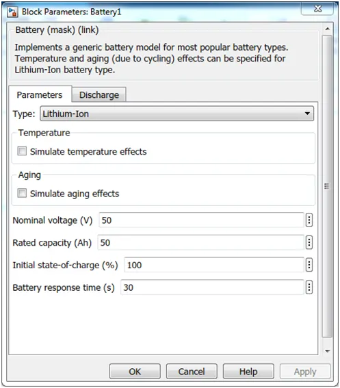
Lithium ion (Li-ion) batteries are now considered to be the standard for modern battery electric vehicles. There are many types of Li-ion batteries that each have different characteristics, but vehicle manufactures are focused variants that have excellent longevity. Compared to other mature battery technologies, Li-ion offers many benefits. For example, it has excellent specific energy (140 Wh/kg) and energy density, making it ideal for battery electric vehicles. Li-ion batteries are also excellent in retaining energy, with a self-discharge rate (5% per month) that an order of magnitude lower than NiMH batteries. However, Li-ion batteries also have some drawbacks as well. Comparatively, Li-ion batteries have been a very expensive battery technology
controlled Current Source:-
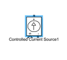
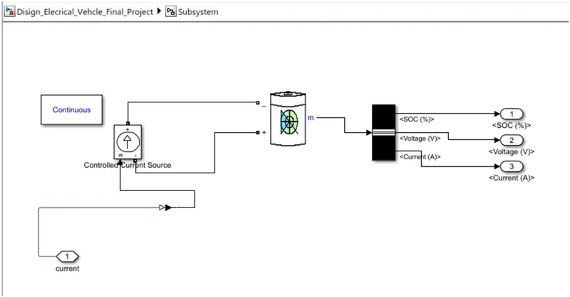
a controlled current source is connected to the lithium battery. this controlled current source provided will initiate the flow of current from the battery to the motor and during regenerative braking from the motor to the battery.
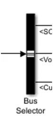
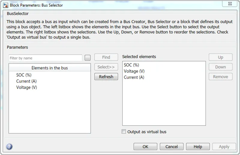
Bus selector
Fuel consumption and emission tests are performed on chassis dynamometers. Tailpipe emissions are collected and measured to indicate the performance of the vehicle.
Another use for driving cycles is in vehicle simulations. More specifically, they are used in propulsion system simulations to predict performance of internal combustion engines, transmissions, electric drive systems, batteries, fuel cell systems, and similar components.
Some driving cycles are derived theoretically, as it is preferred in the European Union, whereas others are direct measurements of a driving pattern deemed representative.
There are two types of driving cycles:
- Transient driving cycles involve many changes, representing the constant speed changes typical of on-road driving.
- Modal driving cycles involve protracted periods at constant speeds.
Longitudinal Driver:
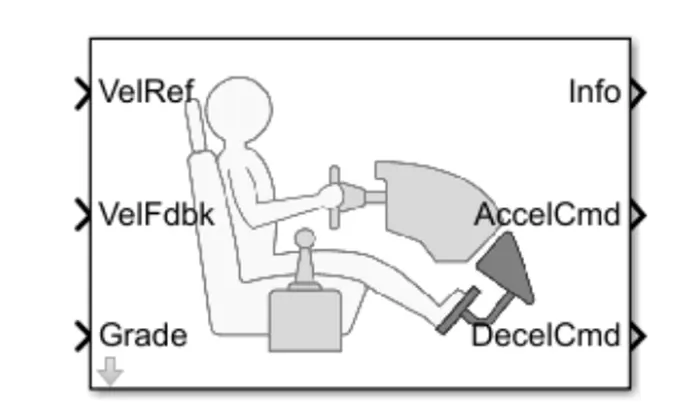
- Longitudinal Driver is an inbuilt block provided by the powertrain blocks.
- It is a parametric longitudinal speed tracking controller for generating normalized Acceleration and Braking commands based on reference and feedback velocities,
- The VelFdbk port corresponds to the feedback velocity. The actual velocity output given by the vehicle body is connected here. By comparing the actual (feedback) velocity with the reference velocity, the driver block generates acceleration and braking signals in order to minimise the error between the two concerned velocities.
- Grade corresponds to the grade angle. For this simulation, no inclination is considered and hence, a constant block with value 0 is connected.
- Info gives the output for the bus signal for different block calculations like the difference in reference vehicle speed and vehicle speed, etc.
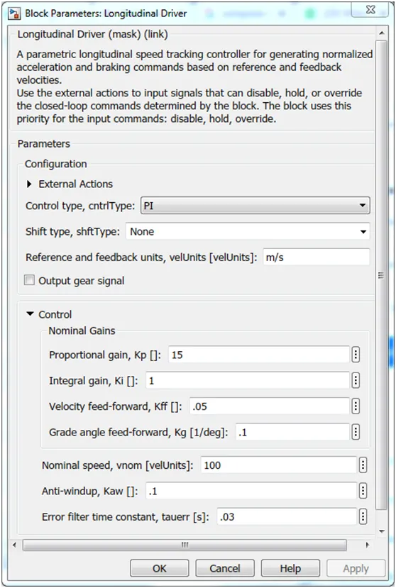
- AccelCmd&DecelCmd correspond to the acceleration and deceleration commands generated respectively and are connected to the corresponding ports of the Controlled PWM Voltage block Here, the selected control type is Pl. Accordingly, the block implements proportional-integral (PI) control with tracking windup and feed-forward gains.
Reference Velocity (Drive Cycle):
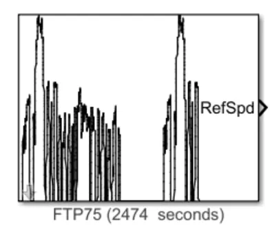
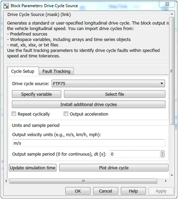
- The Drive Cycle Source block is used to provide the reference speed for the simulation.
- It generates a standard or user-specified longitudinal drive cycle.
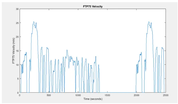
this is the plot of the FTP75 drive cycle
Distance in km/hr
The scope will display velocity of the vehicle in km/hr to measure the distance in km, an integrator block is used because the interaction of velocity will give us distance and 3600 constant blocks are used because 1hr=3600sec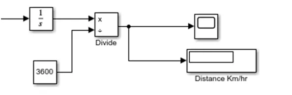
thus scope 5 will give a distance graph
Simulink Explanation:-

The system is running for simulation for 1000s which is the total time for which the input drive cycle is defined.
A Solver Configuration is added to ensure proper solving of the mathematical equations by the model.
- Scopes are connected to analyze different outputs such as the SOC of the battery, the reference velocity & the actual velocity of the vehicle and the distance covered by the vehicle during the total run
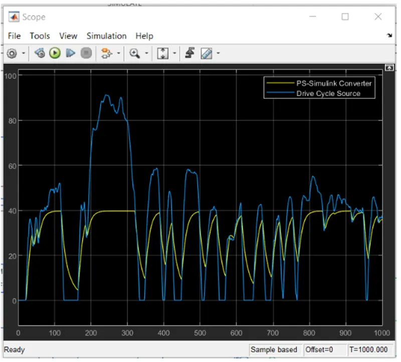
The blue line is a graph of the drive cycle source and the yellow line shows the corresponding velocity graph
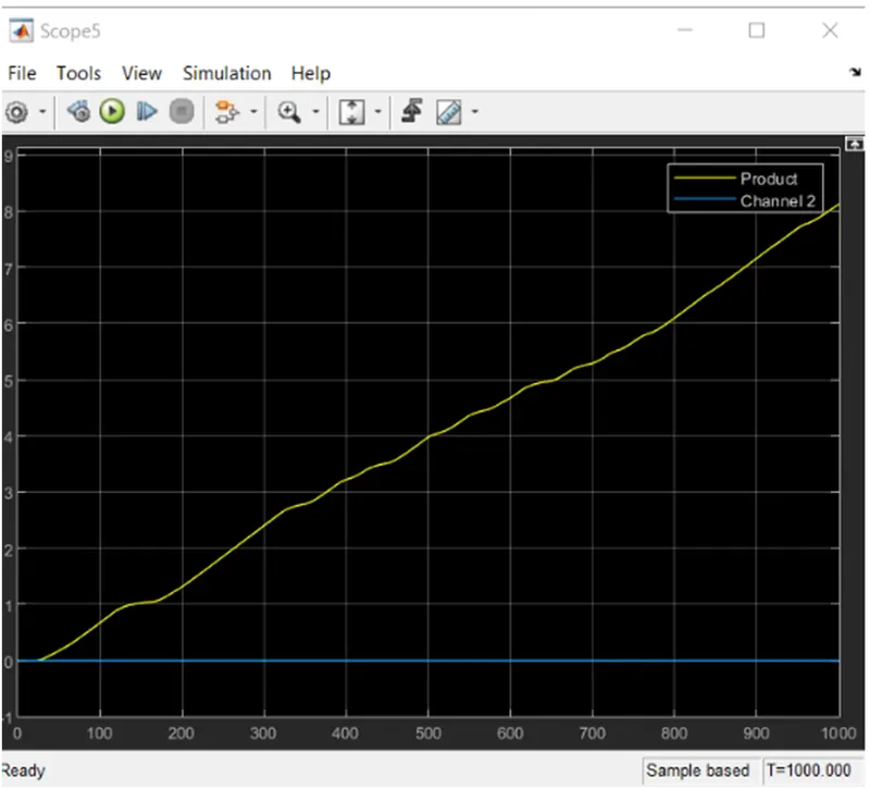
the yellow line shows the distance covered by the electrical car
3) SOC calculation:
the change of SOC is given below
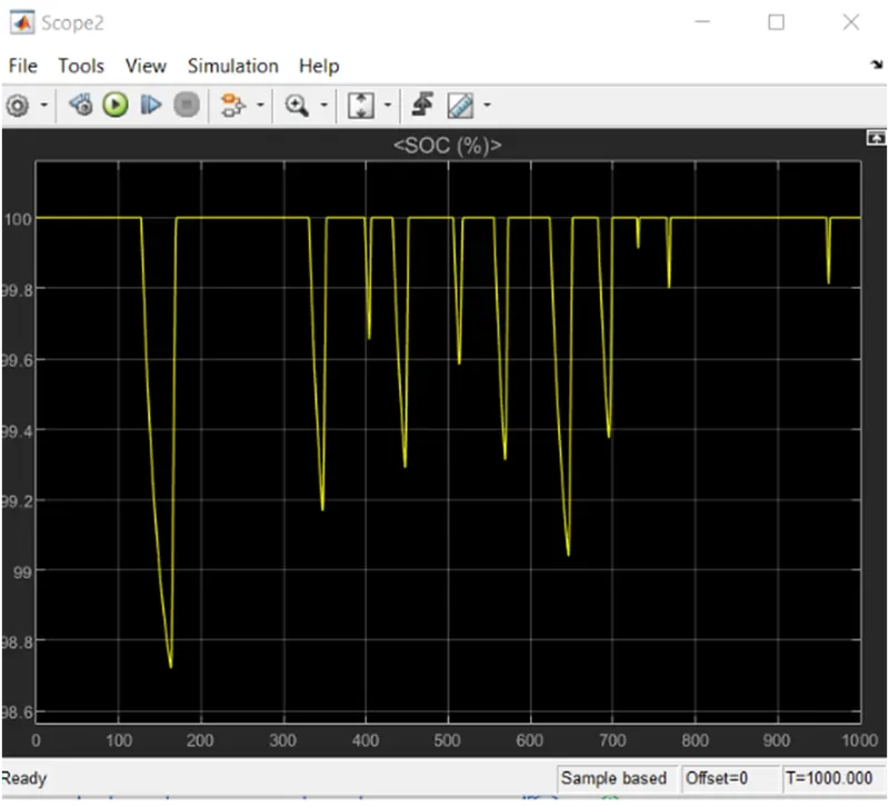
the change of battery current is given below
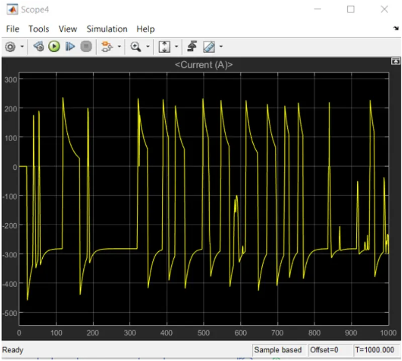
CONCLUSION:
from the above model and from the assumed parameters we found that the velocity of an electric vehicle is 35.96 km and the distance covered by the electric vehicle is 8:121 km and also the variation of SOC and the battery current and battery voltage is also studied.