Final Project: Design of an Electric Vehicle
AIM :-
Design of an Electric Vehicle
objective:-
ELECTRIC CARS:HOW THEY WORK
An electric car is powered by an elecrtric motor rather than a gasoline engine .the electric motor gets its power from a controller . the controller is power from an arry of rechargeblebatteries.
we are creating a MATLAB model of electric car which uses a battery and a DC motor.
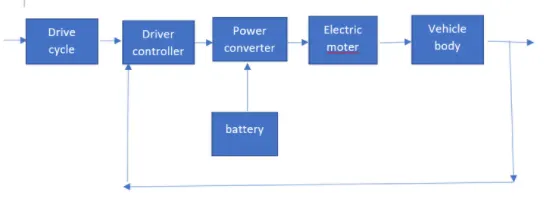
as shown in above block fig we will make matlab simulink model of electric car,first we given cycle than a drive ,we will make two subsystem lastly we will see inputdrive cycle and output velocity of vehicle there should not be much difference in them ans by running this drive cycle we will see state of charge of battery ,it must drain now we will see the simulink model and discuss each part of it
MATLAB model of electric car which uses a battery and a DC motor
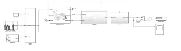
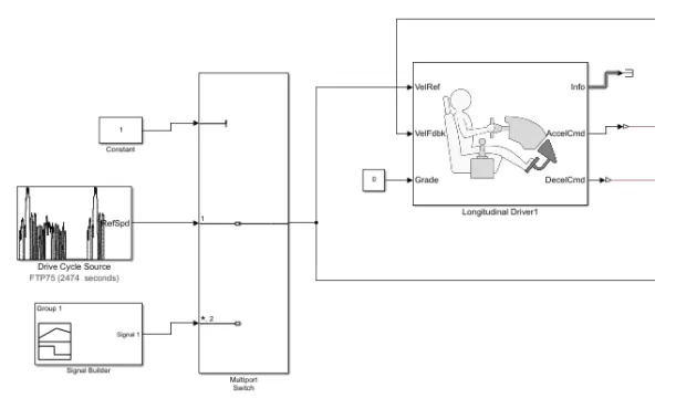
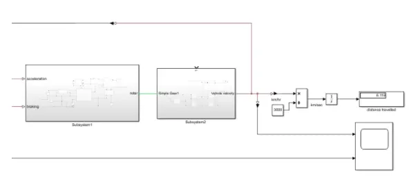
--------system level configurations
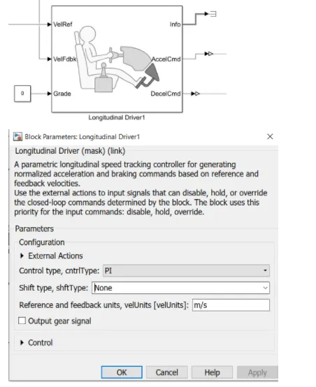
LOngitudinal driver 1
the longitudinal driver block implements a longitudinal speed tracking controller .based on refernce and feedback velocities ,the block generates normalized acceleration and braking commands that can very from 0 through
1.you can use the block to model the dynamic response of a drive or to generate the commands necessary to track a longitudinal drive cycle.
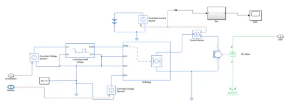
subsystem1
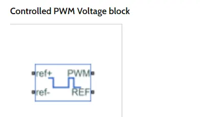
the controlled PWM voltage block represent a pulse width modulaed (PWM) voltage source
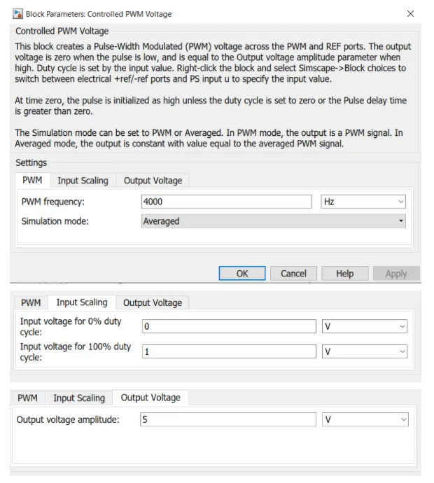
this block produced PWM signal given as input the H bridge ,a controlled voltage source block is used to produced voltage equal to the acceleration command between 0& 1 this voltage is given as inpu to the controlled PWM voltage'
block
under block parameter ,simulation mode is set as averged for fast simulation .input voltages for 0% duty cycle &100 duty cycle is set as 0&1 ,respectively .all other
parameters are kept as default.
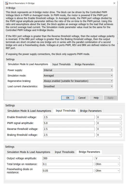
H-bridge block represent an H bridge motor driver.
pwm -the bridge block output is a controlled voltage that depends on the input signal at the PWM port
it controls the power input to the motor according to the load requirements by controlling the input voltage to the motor .
H-bridge is configured to have its power supply internal
simulation mode is configured as averaged to achieve fast simulation regeneration braking is also enabled
output voltage amplitude is set equal to the rated voltage of the motor ,300v .all other parameter are kept as default.
for braking command ,a controlled voltage source block is used to produce voltage equal to the deceleration command from the driver.
dc motor
https://www.mathworks.com/help/physmod/sps/ug/example-modeling-a-dc-motor.html
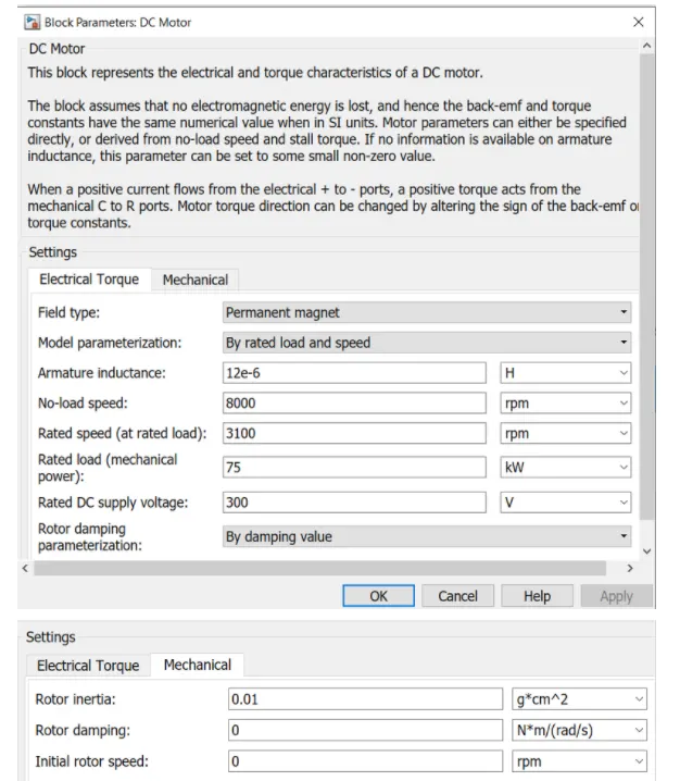
this block represent the electrical and torque characteristics of a DC motor . port connection are made as shown in subsystem 1 under block parameter electrical torque tab.
model parameterization is changed to by rated load &speed
No-load speed ,rated speed ,rated load & rated load &speed
DC supply voltage is configured with values 8000 rpm ,3100rpm ,75kw,&300v respectiveiy and all other parameter are kept as default.
the rated power the motor is calculated by considering the force acting on the vehicle
SOC
this subsystem taken current as input and given the battery SOC% as out put a controlled current source block is used and connectded with the battery this block drains the battery with same current drawn by the motor and also recharges during regenerative braking.
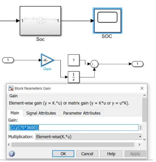
this block estimates the battery SOC% using coulomb counting method.it taken current as the input gives SOC% as output .initial SOC of the battery is assumed to be
100% and while calculating the SOC, battery capacity is assumed to be 100 ah.
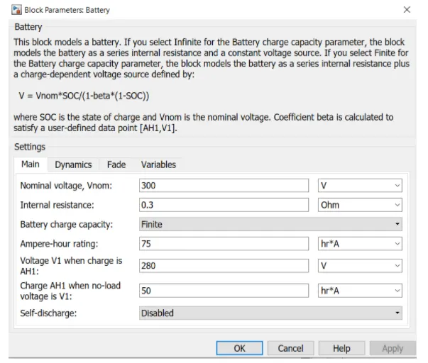
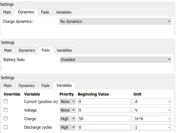
BATTERY
norminal voltage & internal resistance is set to 300v & 0.3 ohms ,respectively .all other parameter are kept default.
solver configuration
f(x)=0
solver configuration it provides solver setting information to model.
CURRENT SENSOR
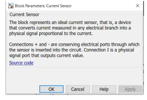
Ammeter -it measure current and it is and it si connected with motor and h bridge in series it is used to indicate state of charge.
controlled voltage source
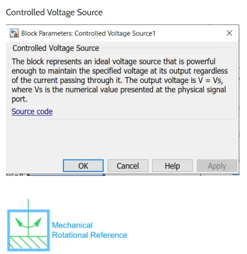
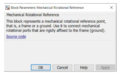
mechanical rotational refernce is connected tothe C port of the DC motor block
subsystem2
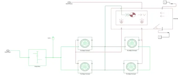
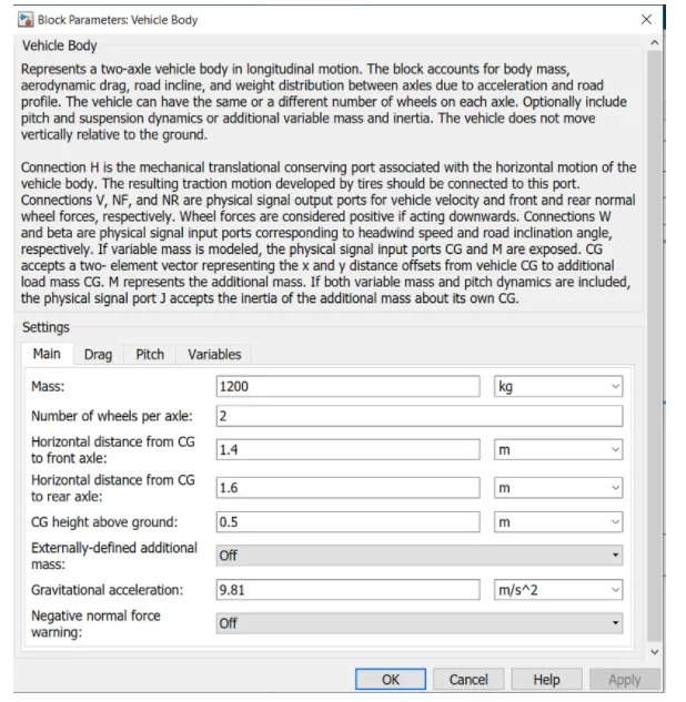
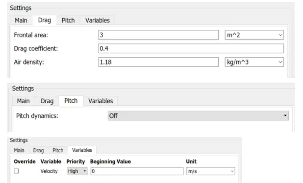
vehicle body
the vehicle body block represents a two axle vehicle body in longitudinal motion. the vehicle can have the same or a different number of wheels on each axle
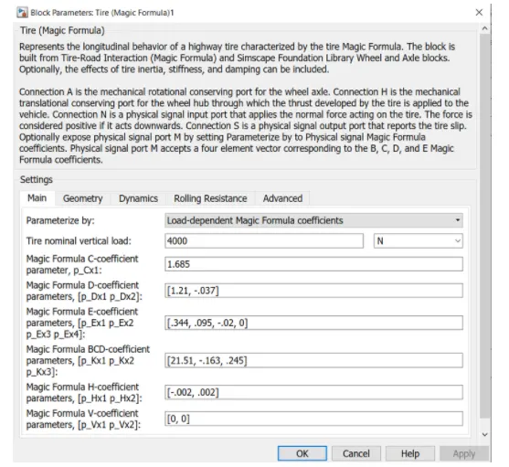
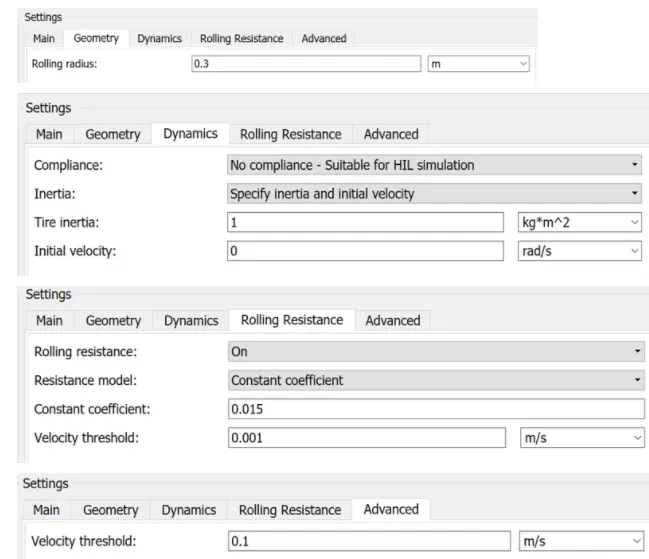
tire (magic formula)
the tire specifcation are show as below we choose
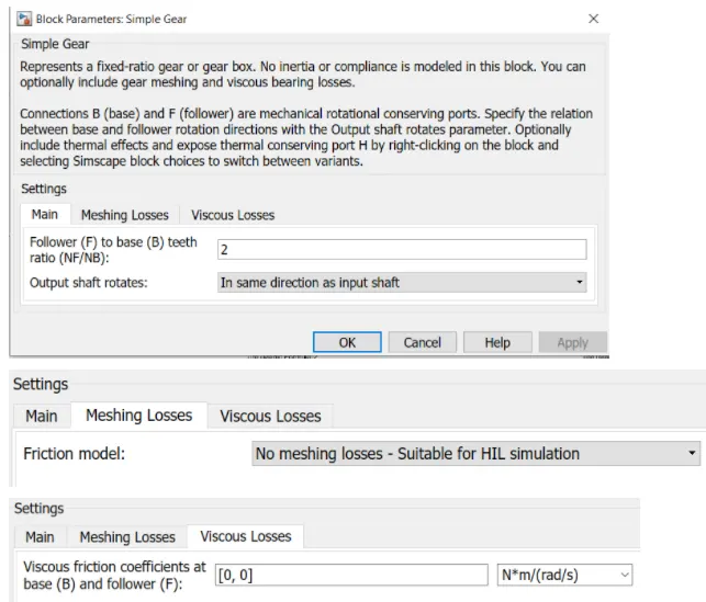
simple gear
Simple Gear Train- The simple gear train is used where there is a large distance to be covered between the input shaft and the output shaft. When examining simple gear trains, it is necessaryto decide whether the output gear will turn faster, slower, or the same speed as the input gear
distance travel:

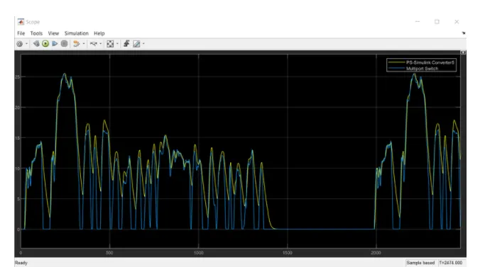
vechicle velocity compared with input cycle result
conclusion
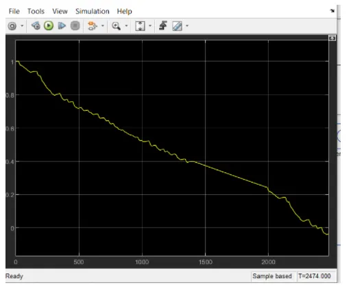
we run the electric car model in simulink environment the output velocity of vehicle and and given drive cycle input match so we can asy vehicle is reunning as per our required drive cycle the ans as the vehicle run the battery drains the soc also reduced ,the distance travel is 6.1km.