Design of 4-Wheel small passenger car using Simulink
4-W Electric vehicle Design on Simulink
The advancement of Semiconductors and the depletion of oil reserves combined with the issue of global warming caused by air pollution from automotive vehicles motivated the auto Industry towards electrically powered motor vehicles, as a sustainable mode of transport for humanity. In this project, we are going to develop a small electric motor drive train for a small passenger vehicle. The steps in this study involve,
- Develop an understanding of system-level configuration
- Defining model parameters
- Understanding the results for FTP75 drive cycle response for the vehicle
- Concluding the results.
Introduction - The concept of an electric vehicle is not new as a matter of fact it was firstly introduced in the year 1890 in the USA by William Morrison, The automobile developed was capable of running at 23 kmph or 14 mph, But the concept of the modern-day electric vehicle was introduced by General Motors in the year 1997, GM Ev1 was the first car which can be classified as a proper electric vehicle. In the past 2 decades, Tesla motors have been a Synonym for the electric vehicle with their high powered Induction motors and long-range batteries the company really paved the way for modern electric vehicles.
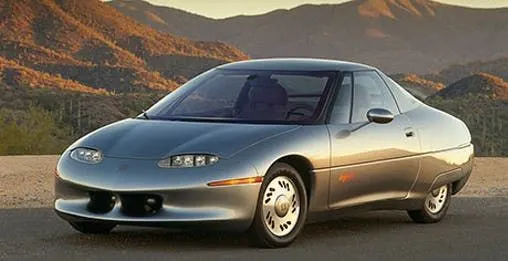
GM EV1
Components of an electric drive train - To understand the working of electric vehicles we have to first understand the various component which facilitates the operation of an electric vehicle drive train.
The electric drive train is fairly simple in terms of components it consists of either an AC motor or a permanent magnet DC motor or PMDC, a battery source with an Inverter, and a system-level controller. The block diagram below will explain the connection between different components.
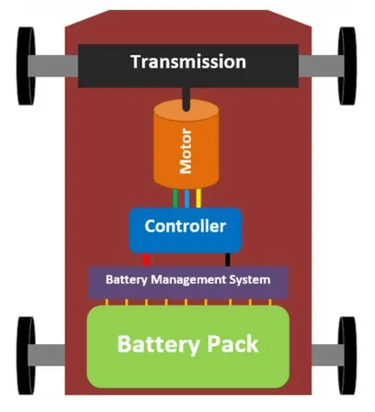
The engine of a traditional car is replaced by a motor and the fuel tank is replaced by a battery. Only the Battery Pack and Motor account for over half of the total weight and cost of the car. As you can see, the primary components of an electric vehicle are the battery pack, battery management system (BMS) controller, motor, and transmission.
Now, let us understand the basic major parts of the Ev drive train one-by-one in detail,
1. EV Batteries - Although batteries are the primary source of energy for electric vehicles, it is crucial to note that they are not the only source of energy. There are other ways to power an EV, such as using a fuel cell or supercapacitors, but these are still in the development stage, and no commercial vehicles use them.
EVs are propelled by a pack of hundreds, and even thousands, of batteries. To give you an idea, the Tesla Model S has 7000 batteries and the Chevrolet Spark has 600 batteries. The Cell, Battery Module, and Battery Pack make up the entire power system for an Ev. The overall battery pack can be further divided into 3 major parts,
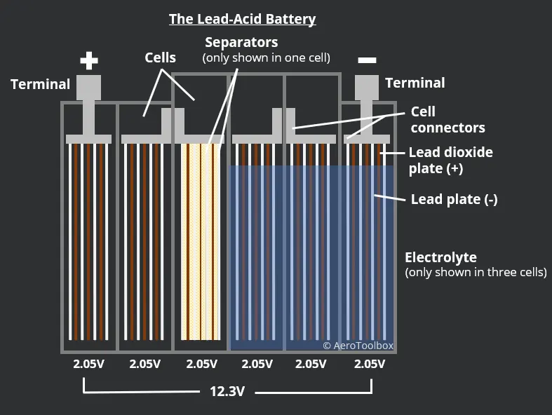
- Cell - A single battery is referred to as a cell. Based on the chemistry, a cell can have a variety of sizes and shapes. Lead-Acid Batteries and Lithium Batteries are the most commonly used battery types. A lithium battery has a voltage rating of 3.7V while a lead-acid battery is rated at 12V, This voltage is insufficient to power an electric vehicle. Tesla, for example, has a battery pack voltage of 356 volts.
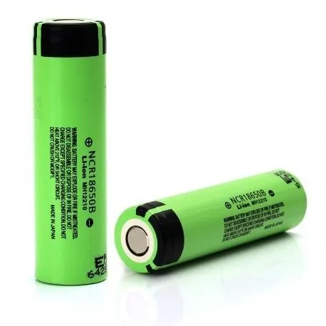
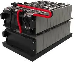
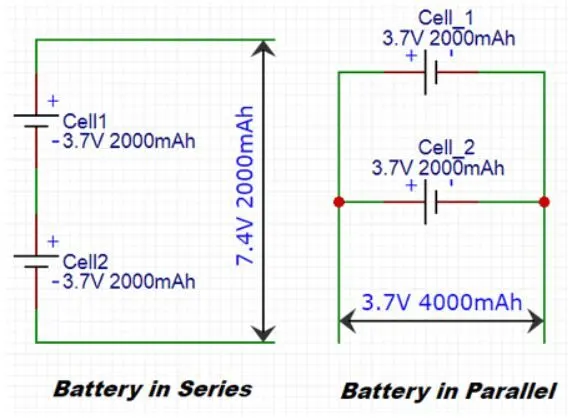
- Battery Configuration/Module - Battery packs/modules, which are formed by combining more than one battery, are used to obtain a higher voltage from 3.7v lithium cells. When two batteries are connected in series, their voltage ratings are added, and when two batteries are connected in parallel, their Ah ratings are added. A single lithium cell voltage and Ah rating is not enough to drive an EV, so these cells are connected in series and parallel configuration to increase the resulting system voltage. This pack is called a module.
- Battery pack - Once the voltage and Ampere ratings are obtained for the electric vehicle a battery pack is assembled and placed inside the electric vehicle. Since the lithium cells are unstable in nature if proper battery control is not provided it may result in overheating or short-circuiting. to overcome this problem a battery management system must be installed with the battery pack to provide proper safety during charging and motoring operations. The complete arrangement along with the BMS, cooling system casing, and the battery modules all together is called a Battery Pack of a car. These packs will normally be big and occupy the entire floor area of an EV.
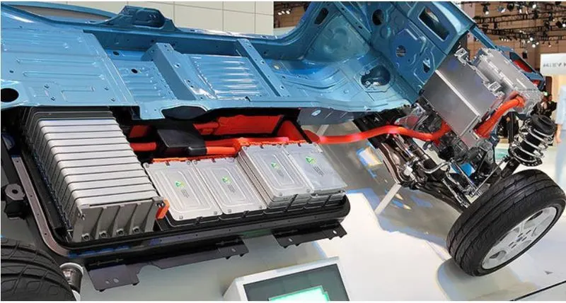
Section view of NISSAN Leaf showing battery pack on the floor.
- BMS or Battery management system - A battery management system computes the overall power in each cell during charging and discharging and keeps the battery pack safe from overloading or overheating. Every BMS measures only three vital parameters of the battery: voltage, current, and cell temperature. It compares these values to safety limits on a regular basis and disconnects the load if they exceed the threshold values. Aside from safety, the BMS is also used for computational purposes, such as measuring the SOC and SOH of a battery. SOC stands for the state of Charge and is the estimation for the running time of the electric vehicle.
2. Motors - Motors are the engine of the Electric vehicle. The electric power from the battery is converted to Rotational mechanical power by the electromagnetic machine/motor.
Basically, 2 major types of motors are employed in an electric vehicle drive system these are
- DC motors
- AC Induction motors
Furthermore, DC motors can be classified into 2 more types,
- Brushless DC motors and,
- Brushed DC motor
The BLDC motors have a constant torque and fast response making them suitable for automotive applications. Apart from EV’s these motors are also used in wipers, power windows, etc. the BLDC motors can be further classified into 2 types
- BLDC hub motors - These motors are generally used in 2-Wheeler applications. The rim of the wheel forms the motor. These motors are also called the BLDC outrunner motor. The advantage of this type of motor is that there is less mechanical loss and since there is no transmission unit cost and weight is reduced. The downside is that we cannot have a gear ratio of high-power motors due to size limitations.
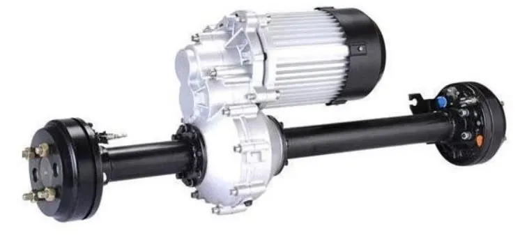
- BLDC In-runner motors - Another type of BLDC motor is the In-runner type. They are used in applications where a transmission unit is required. They are normally coupled along with a differential for 3-wheeled or 4-wheeled EVs. These motors look like normal motors with a shaft and the shaft rotates when the motor is powered
AC Induction motors - Most Modern day Electric cars like Tesla uses an AC Induction motor. The Tesla Model S for instance uses a 3-phase AC Induction Motor. The reason why these motors are selected is that they do not have permanent magnets within them and thus low cost. It also has good life since there are no magnets, magnets would lose their tendency in a day course. The downside of the motor would be that it is hard to control the speed and torque of the motor and advanced circuitries are required.
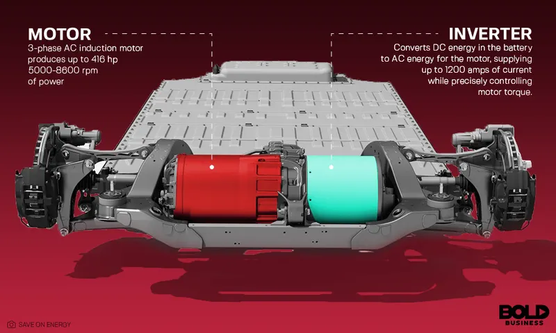
The AC induction motor requires a Clarke's And Park's transformation circuit inverter for their operation which increases the complexity of the inverter circuit.
In this project, we have assumed a BLDC motor for our driving mechanism.
3. Controller or ECU - The controller gets all the inputs from the user like the amount of throttle (acceleration), breaks pressure, driving mode, etc and controls the speed of the motor accordingly. A controller is often a generic term and it might include other circuits like a DC-DC converter, Speed controller, Inverter, etc. The DC-DC converter is used to power all the peripherals of the car like the infotainment system, Headlights, and other low-level electronic devices.
For a DC motor Drive, a PWM and an H bridge circuits are used to control the speed and torque of the motor within safe limits. Depending on the requirement the output signal of the inverter can be a square wave type or sinusoidal type.
Apart from this the controller also takes care of regenerative braking. It is the process of converting kinetic energy into electric energy. That is when the EV runs down a slope the motor is rotating freely due to the kinetic energy, at this situation the motors can be made to act as a generator so that the power thus obtained can be used to charge the batteries.
For more information on control strategies please refer to this article - https://skill-lync.com/student-projects/week-7-challenge-dc-motor-control-343
Modeling Parameters -
- Vehicle weight - 500 kg
- Payload weight - 320 kg
- Motor type - BLDC In runner motor
- Vehicle Drive - Rear wheel drive
- Motor controller - H-bridge Inverter with Sinusoidal pulse width modulation
Force calculation Model -
The motor power for a vehicle is calculated by calculating the total Tractive force acting on the vehicle in extream conditions, Mainly these forces act on the vehicle -
- Friction force
- Hill climb force
- Air Drag Force
- Acceleration force
The Total Tractive Force is Given By -
Force(tractive) = Friction force + Airdrag force + Hill Climbing force + Acceleration force
Friction Force or Rolling Resistance force -
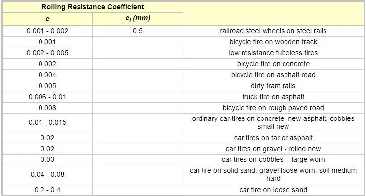
The rolling resistance can be expressed by the generic equation
Fr = c W (1)
where
Fr = rolling resistance or rolling friction (N, lbf)
c = rolling resistance coefficient - dimensionless (coefficient of rolling friction - CRF)
W = m ag
= normal force - or weight - of the body (N, lbf)
m = mass of body (kg, lb)
ag = Acceleration of gravity (9.81 m/s2, 32.174 ft/s2)
Rolling resistance coefficient chart-
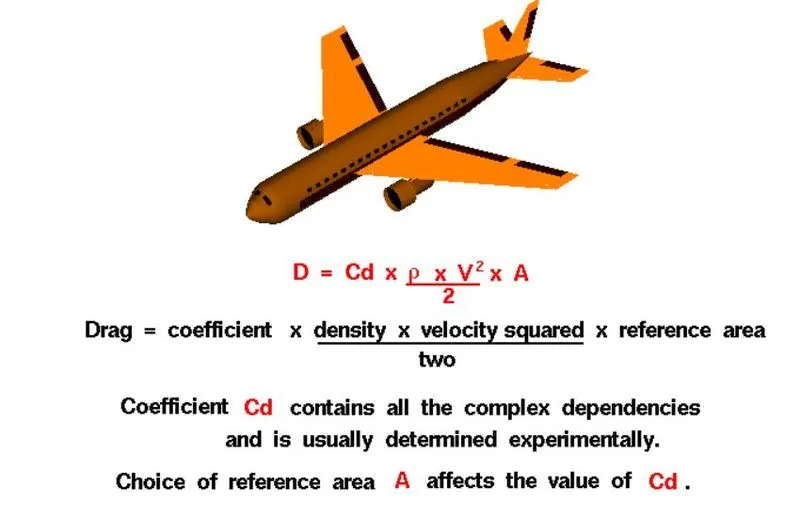
Air Drag force on a car - Aerodynamic Drag force can be defined as resistance force offered by the Fluid medium or air to the body when the body is passing through the fluid medium or air.
Drag depends on the density of the air, the square of the velocity, the air's viscosity and compressibility the size and shape of the body, and the body's inclination to the flow.
Hill Climb Force -
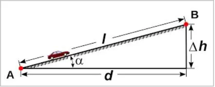
Force(hc) = `m*g*sintheta`
where,
`m`- a mass of the vehicle
`g`- acceleration due to gravity
`sintheta`- Grade angle for the hill
In this project, we have excluded the acceleration force from the calculations,
Putting all the values in the excel calculator we get,
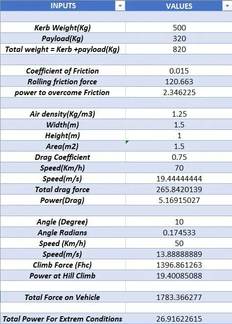
- The total tractive force on the vehicle is 1783.36 N
- The total motor power required by the vehicle is 26.91 kW
Simulink model -
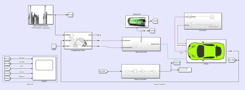
Model SubSystems -
The whole model is divided into various substems, All the initial values are inserted in the model and the subsystems process them into useful signals which can be used for the simulation of the model.
1. Vehicle body -
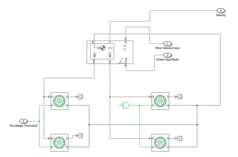
Block used -
- Tire(magic formula)- The Tire (Magic Formula) block models a tire with longitudinal behavior given by the Magic Formula, an empirical equation based on four fitting coefficients. The block can model tire dynamics under constant or variable pavement conditions.
- vehicle body - The Vehicle Body block represents a two-axle vehicle body in longitudinal motion. The vehicle can have the same or a different number of wheels on each axle. For example, two wheels on the front axle and one wheel on the rear axle. The vehicle wheels are assumed identical in size. The vehicle can also have a center of gravity (CG) that is at or below the plane of travel.
The block accounts for body mass, aerodynamic drag, road incline, and weight distribution between axles due to acceleration and road profile. Optionally include pitch and suspension dynamics. The vehicle does not move vertically relative to the ground.
- PS-Terminator -Terminator for unconnected physical signal outputs
- Inertia - The Inertia block represents an ideal mechanical rotational inertia, described with the following equation:
`T = J*((domega)/dt)`
2. Motor Control -
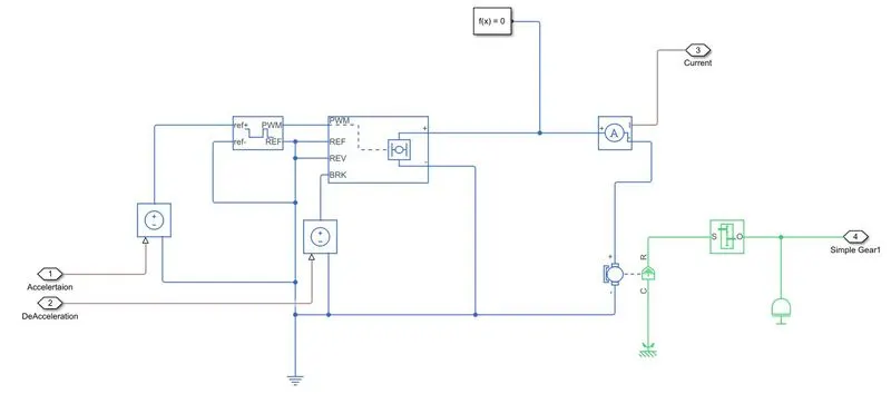
Block used -
- Controlled PWM Voltage - This block creates a Pulse-Width Modulated (PWM) voltage across the PWM and REF ports. The output voltage is zero when the pulse is low and is equal to the Output voltage amplitude parameter when high.
- H-bridge - The H-Bridge block represents an H-bridge motor driver. The block has the following two Simulation mode options:
-
PWM— The H-Bridge block output is a controlled voltage that depends on the input signal at the PWM port. If the input signal has a value greater than the Enable threshold voltage parameter value, the H-Bridge block output is on and has a value equal to the value of the Output voltage amplitude parameter. If it has a value less than the Enable threshold voltage parameter value, the block maintains the load circuit using one of the following three Freewheeling mode options:-
Via one semiconductor switch and one freewheeling diode -
Via two freewheeling diodes -
Via two semiconductor switches and one freewheeling diode
The first and third options are sometimes referred to as synchronous operations.
-
-
The signal at the REV port determines the polarity of the output. If the value of the signal at the REV port is less than the value of the Reverse threshold voltage parameter, the output has positive polarity; otherwise, it has negative polarity.
-
Braking mode is invoked when the voltage presented at the BRK port is larger than the Braking threshold voltage.
-
- DC-Motor - The DC Motor block represents the electrical and torque characteristics of a DC motor using the following equivalent circuit model
- Ideal Voltage source - The Controlled Voltage Source block represents an ideal voltage source that is powerful enough to maintain the specified voltage at its output regardless of the current flowing through the source.
The output voltage is V = Vs, where Vs is the numerical value presented at the physical signal port.
- Current Sensor - The Current Sensor block represents an ideal current sensor, that is, a device that converts current measured in any electrical branch into a physical signal proportional to the current.
Connections + and – are electrical conserving ports through which the sensor is inserted into the circuit. The connection I is a physical signal port that outputs the measurement result.
- Inertia - The Inertia block represents an ideal mechanical rotational inertia
- Gearbox - The Gear Box block represents an ideal, nonplanetary, fixed gear ratio gearbox. The gear ratio is determined as the ratio of the input shaft angular velocity to that of the output shaft.
- Rotational Reference - The Mechanical Rotational Reference block represents a reference point, or frame, for all mechanical rotational ports. All rotational ports that are rigidly clamped to the frame (ground) must be connected to a Mechanical Rotational Reference block.
- Electrical Reference - The Electrical Reference block represents an electrical ground. Electrical conserving ports of all the blocks that are directly connected to the ground must be connected to an Electrical Reference block. A model with electrical elements must contain at least one Electrical Reference block.
3. Environment subsystem - The environment subsystem block provides the physical input values for wind velocity and Gradability in the vehicle body block by using a Constant physical signal block
4. Drive Cycle -
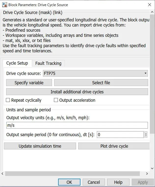
- The Drive Cycle Source block generates a standard or user-specified longitudinal drive cycle. The block output is the specified vehicle longitudinal speed
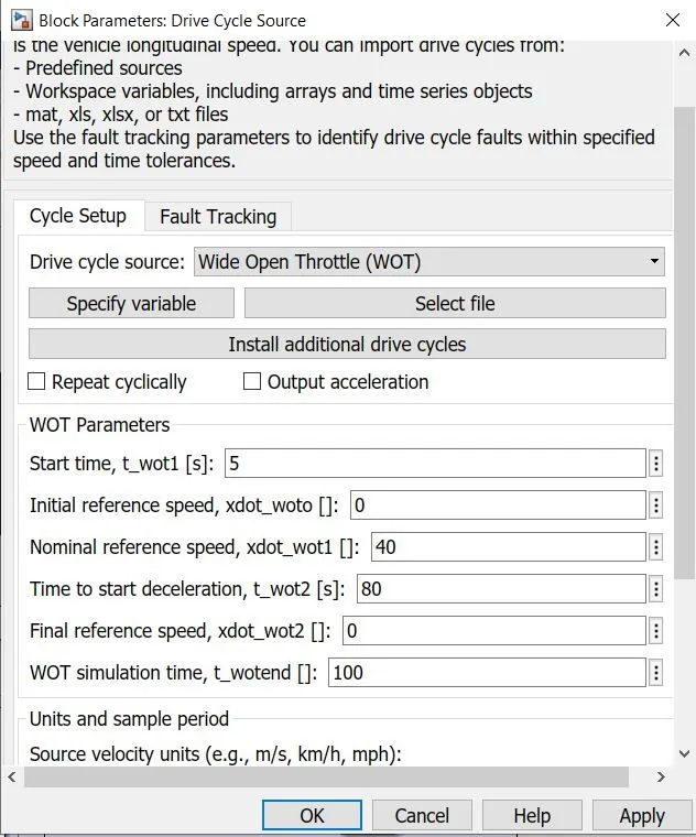
- In this project, we have used 2 inputs the FTP75 cycle and Wide-open throttle cycle.
5. Longitudinal Driver -
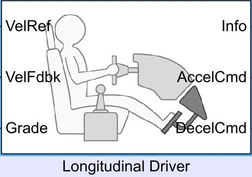
- The Longitudinal Driver block implements a longitudinal speed-tracking controller. Based on reference and feedback velocities, the block generates normalized acceleration and braking commands that can vary from 0 through 1.
6. Battery Soc Subsystem -
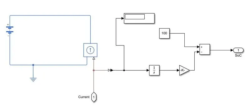
Block used -
- Battery - The block represents a simple battery, the voltage is kept at 110V DC.
- Electrical ref. - The Electrical Reference block represents an electrical ground. Electrical conserving ports of all the blocks that are directly connected to the ground must be connected to an Electrical Reference block. A model with electrical elements must contain at least one Electrical Reference block.
- Ideal current source -
The Controlled Current Source block represents an ideal current source that is powerful enough to maintain the specified current through it regardless of the voltage across the source.
The output current is I = Is, where Is is the numerical value presented at the physical signal port.
The positive direction of the current flow is indicated by the arrow.
- Integrator - The Integrator block outputs the value of the integral of its input signal with respect to time.
- Gain - The Gain block multiplies the input by a constant value (gain). The input and the gain can each be a scalar, vector, or matrix.
- Subtract - The Sum block performs addition or subtraction on its inputs. The Add, Subtract, Sum of Elements, and Sum blocks are identical blocks. This block can add or subtract scalar, vector, or matrix inputs. It can also collapse the elements of a signal and perform a summation.
- Constant -
The Constant block generates a real or complex constant value signal. Use this block to provide a constant signal input. The block generates scalar, vector, or matrix output, depending on:
-
The dimensionality of the Constant value parameter
-
The setting of the Interpret vector parameters as 1-D parameter
The output of the block has the same dimensions and elements as the Constant value parameter. If you specify for this parameter a vector that you want the block to interpret as a vector, select the Interpret vector parameters as a 1-D check box. Otherwise, if you specify a vector for the Constant value parameter, the block treats that vector as a matrix.
-
Results -
Case - I
Grade - 0, Top speed - 90kmph, motor - 28 kW at 110V
Fig. 1.
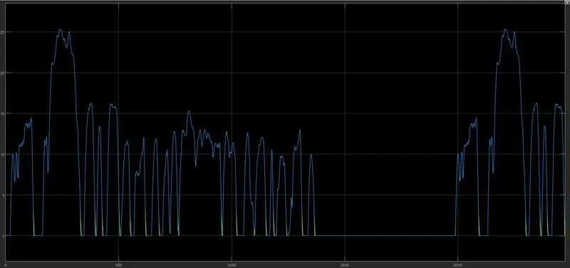
Fig. 2.
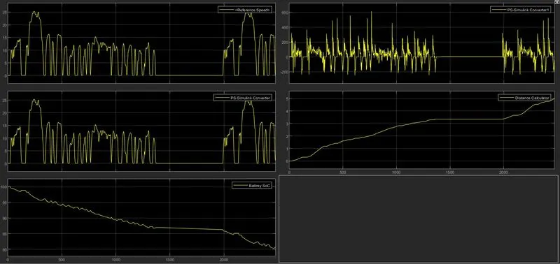
Fig. 3.
Description -
- From the excel calculator, we calculated the power requirement for our motor which is around 28kW for 50kmph speed at a 10-degree grade angle.
- We simulated the model for 0-degree gradability and in fig.2 we can see that the reference velocity is closely followed by the feedback velocity from the vehicle body.
- in the 3rd fig., we can see that the SoC is dropped to 81 percent from its initial value of 100 percent and the total distance covered is around 4.96 km.
CASE - II
Grade - 10 , Top speed - 90 kmph, Motor - 28 kW at 110V
Fig. 1.
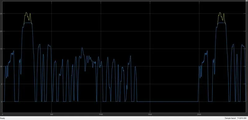
Fig. 2.
Description -
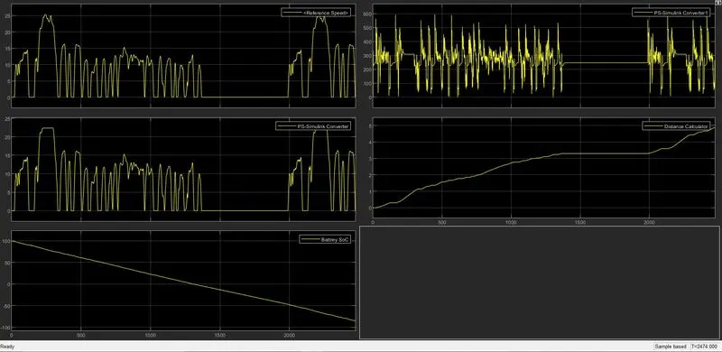
- in this case the reference vel. and the feedback velocity is not identical, as the motor is decided by keeping 50 kmph top speed at grade 10 and the requested speed top speed was 90kmph at grade angle 10.
- The motor is severely underpowered for such kind of operating conditions.
- The SoC value is also below zero which is not a practical condition, Hence we can conclude that this model is not practical and cannot be used in real life.
CASE - III
By keeping the above parameters in mind let's calculate motor power according to drive cycle requirements.
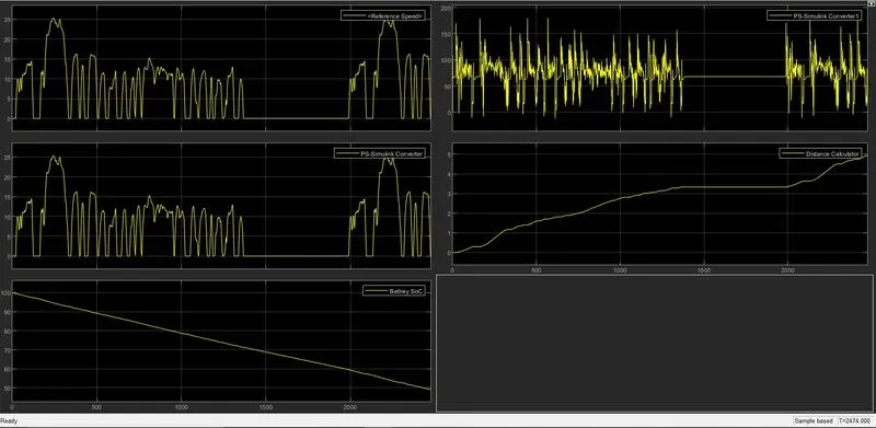
Grade - 10, top speed - 95kmph, motor power - 53 kW at 400V
Fig. 1.
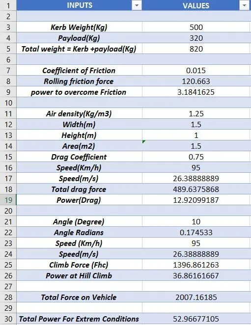
Fig. 2.
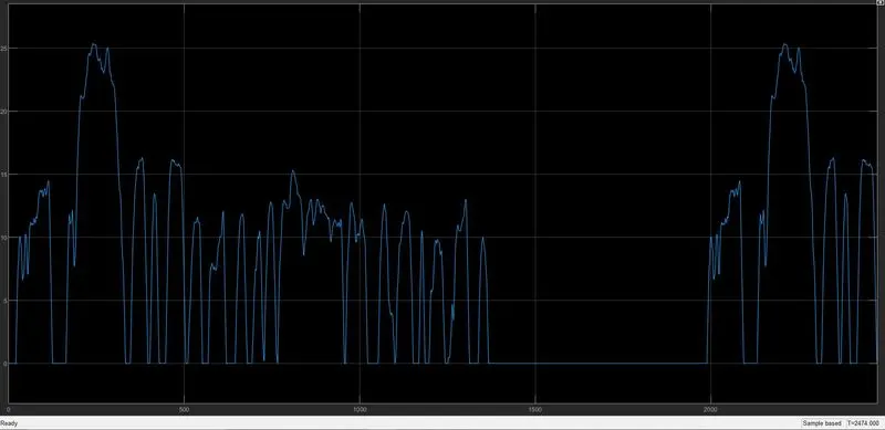
Fig. 3.
Description -
- by changing the motor power and battery to 53kW at 400 V we can see that the input vel. and the actual feedback velocity is similar.
- The motor is accurately powered for the given conditions.
- The SoC value is dropped to 50 percent approx value.
- in this case, we have simulated to the most extreme condition and the vehicle responded accordingly.
Conclusion -
- In this project, we gained knowledge about electric vehicles.
- The importance of vehicle dynamics and Force and power calculation is understood through this project.
- The project explains the importance of motor power calculation for designing an electric vehicle.
- The use of Excel calculators and Simulink is explained in the project.
Model Link - https://drive.google.com/drive/folders/1idneAFHI9B3m55qzaoL-QdZAQQMPtm82?usp=sharing