Control Strategies for a DC drive train
Project on the working of a BJT H-bridge Circuit for DC motor Control
Objectives - In this project we are going to understand the BJT H-bridge circuit for DC motor control by using a Simulink model.
Theory - Before understanding the BJT H bridge we should have a basic understanding of a BJT transistor.
- BJT - A BJT or bipolar junction transistor is a semiconductor device that is used as a switch or an amplifier in an electronic circuit. Depending on the configuration it can be of two types -
1. P-N-P Transistor, current flows from base to Emitter
2. N-P-N Transistor, current flows from emitter from base
A BJT-transistor consist of 3 terminal consisting of a base terminal an emitter and a collector terminal. The base terminal is a part of a signal circuit while the emitter and collector part is connected with the power portion of the circuitry.
In this model, a PNP-type transistor is used and is connected with the H bridge Invertor. In addition to the transistor circuit, a diode is used in parallel to maintain the flow of current in only one direction.
- H-Bridge - The H-bridge inverter circuit is used to convert DC type current to an AC type current. it is also known as a simple inverter.
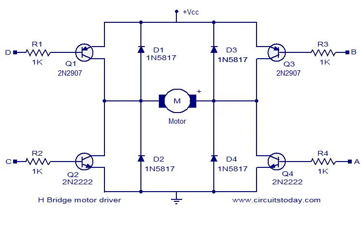
In the above circuit, we can see that there are 4 switches Q1, Q2, Q3, and Q4 connected in series and parallel combination. The load M is connected in the middle and Voltage and ground sources are connected at the top and bottom of the circuit. In order for the circuit to work, Q1 and Q4 must be open at the same time, and to reverse the polarity Q2 and Q3 must be on and Q1, Q2 must be in an off state. The Diode D1, D2, D3, and D4 are used in parallel to maintain the unidirectional flow of the current.
Circuit Diagram -
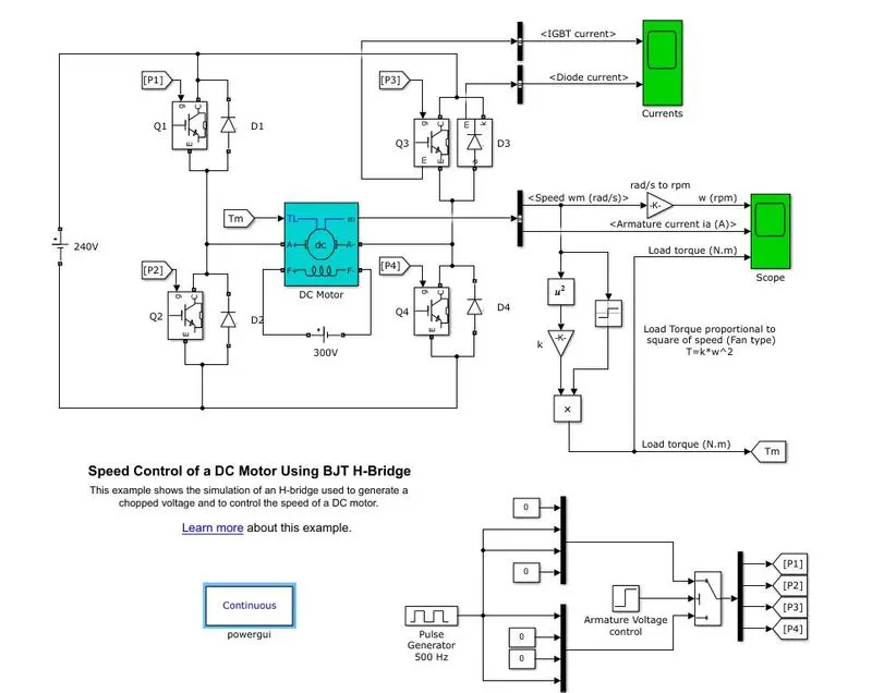
The model works in the forwards biased condition in the first half then in reverse-biased for the remaining half of the cycle. The duty cycle is controlled by a pulse generator block in the Simulink.
#For a duty cycle of 75%
Results -
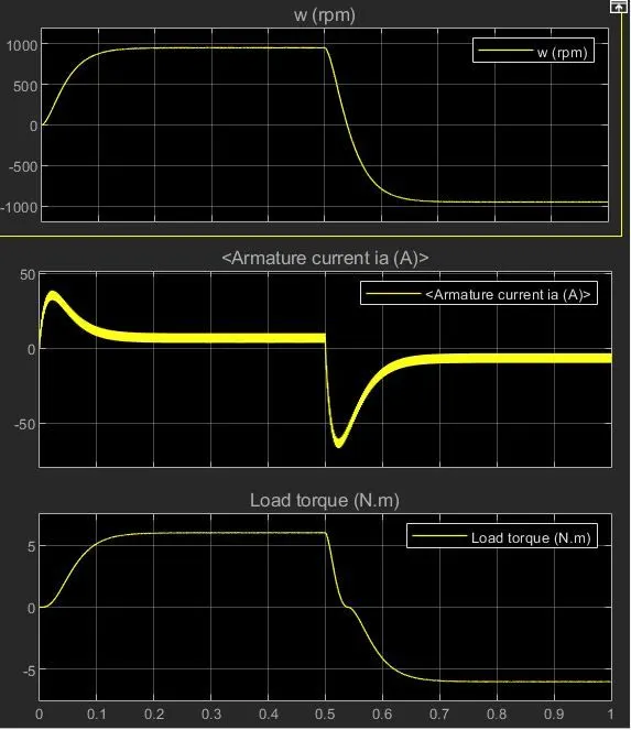
- From the above results, we can see that with a duty cycle of 75% the reverse-biased current will shoot up to -60(A) values.
- The curve is very sharp which indicates a sudden spike in current which can ultimately damage the curcuit.
# when the duty cycle is 50%
Results -
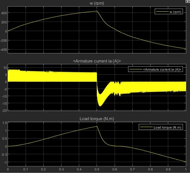
- From the results above we can see that by reducing the duty cycle to 50% the peak of negative current is around -16 Amps.
- The switching curve in achieving constant value in less time as compared to the previous one.
- the spike in the peak value of the current is also less as compared to the previous model.
Conclusion -
From the above results, we can conclude that the sudden increase in current can be limited by reducing the duty cycle.
DC7 four Quadrant circuit
A four-quadrant chopper is one that can operate in all four quadrants. In this chopper, power can flow from source to load or load to source. A Class-E chopper acts as a Step-down chopper in the first and third quadrants, but as a Step-up chopper in the second and fourth quadrants. This chopper is also referred to as a Class-E or Type-E chopper.
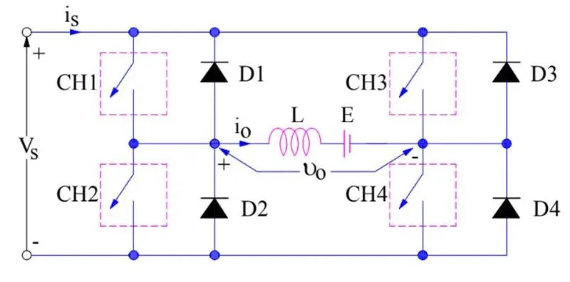
A four-quadrant chopper, also known as a class-E chopper, is made up of four semiconductor switches CH1 to CH4 and four diodes D1 to D4. The four diodes are connected in an anti-parallel configuration.
First Quadrant Operation:
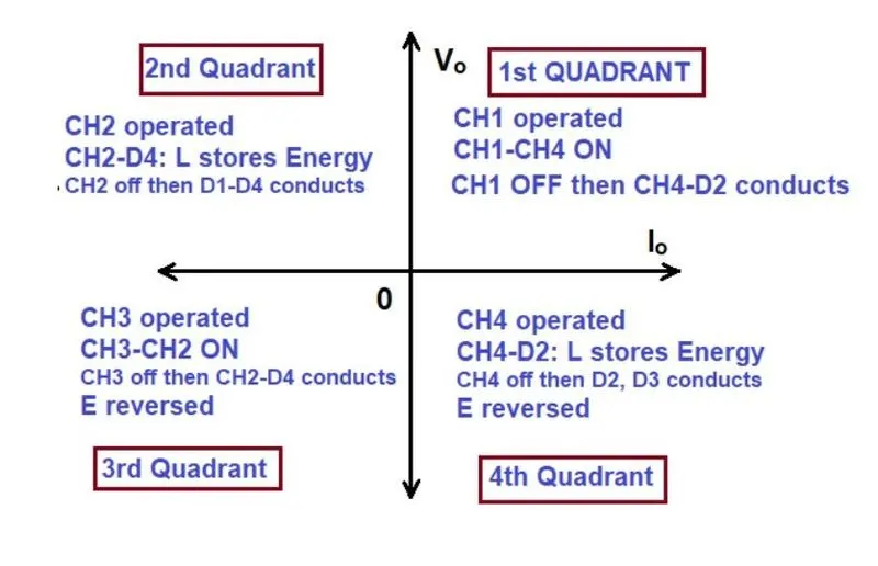
For the first quadrant operation, CH4 is turned on, CH3 is turned off, and CH1 is turned on. When both CH1 and CH4 are turned on at the same time, the load is directly connected to the source, and the output voltage equals the source voltage. Essentially, this means that vo = vs. It is worth noting that the load current flows from source to load, as indicated by the direction of io.
When CH1 is deactivated, the load current flows freely through CH4 and D2. The load voltage and current remain positive during this time.
Thus, both the output voltage vs and load current io are positive and hence, the operation of the chopper is in the first quadrant
Second Quadrant Operation:
To achieve second quadrant operation, CH2 is activated while CH1, CH3, and CH4 are deactivated. When CH2 is turned on, the load's DC source drives current through CH2, D4, E, and L. During the On period of CH2, inductor L stores energy.
When CH2 is turned off, the current returns to the source via D1, D4. It should be noted that (E+Ldi/dt) is greater than the source voltage Vs. Because the load voltage Vo is positive and the input voltage Io is negative, this is a chopper operation in the second quadrant. Because the current is returned to the source, this simply means that the load is transferring power to the source.
For the second quadrant operation, the load must contain emf E as shown in the circuit diagram. In the second quadrant, the configuration operates as a step-up chopper.
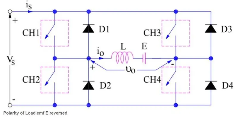
Third Quadrant Operation:
CH1 is turned off, CH2 is turned on, and CH3 is turned on for the third quadrant operation. When CH3 is turned on, the load is connected to the source, and the load voltage equals the source voltage.
However, keep in mind that the polarity of the load voltage vo is the inverse of what is shown in the circuit diagram. As a result, vo is assumed to be negative. Let's take a look at the current state of load current io. It can be seen that io is flowing in the opposite direction as shown in the circuit diagram, and thus is negative.
When CH3 is deactivated, the negative load current freewheels through CH2 and D4. In this sense, vo and io are both negative. As a result, the chopper operates in the third quadrant.
Fourth Quadrant Operation:
To obtain the fourth quadrant operation, CH4 is activated while CH1, CH2, and CH3 are deactivated. In this case, as with the third quadrant operation, the polarity of the load emf E must be reversed.
Positive current flows through CH4, D2, L, and E when CH4 is turned on. Inductance During the time that CH4 is turned on, L stores energy. When CH4 is turned off, current flows back to the source via diodes D2, D3. The load voltage is negative in this case, but the load current is always positive. This results in chopper operations in the fourth quadrant. Power is fed back to the source from the load, and the chopper functions as a step-up chopper.
DC7 - Four-Quadrant Chopper 200 HP DC Drive
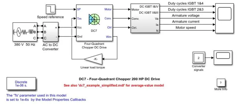
Description -
The 200 HP DC motor is separately excited with a constant 150 V DC field voltage source. The armature voltage is provided by an IGBT converter controlled by two PI regulators. The converter is fed by a 515 V DC bus obtained by rectification of a 380 V AC 50 Hz voltage source. In order to limit the DC bus voltage during dynamic braking mode, a braking chopper has been added between the diode rectifier and the DC7 block.
The first regulator is a speed regulator, followed by a current regulator. The speed regulator outputs the armature current reference (in p.u.) used by the current controller in order to obtain the electromagnetic torque needed to reach the desired speed. The speed reference change rate follows acceleration and deceleration ramps in order to avoid sudden reference changes that could cause armature over-current and destabilize the system. The current regulator controls the armature current by computing the appropriate duty ratios of the 5 kHz pulses of the four IGBT devices (Pulse Width Modulation). For proper system behavior, the instantaneous pulse values of IGBT devices 1 and 4 are opposite to those of IGBT devices 2 and 3. This generates the average armature voltage needed to obtain the desired armature current. In order to limit the amplitude of the current oscillations, a smoothing inductance is placed in series with the armature circuit.
Difference between a BJT - H Bridge and DC7 Four Quadrant
| BJT-H Bridge | DC7 Four Quadrant Chopper |
| It only works in 2 quadrants | It works in all four quadrant |
| Switching of polarity is done by reversing the polarity | Switching is done by interrupting the signals |
| Regenerative braking is not possible | Regenerative braking is possible |
| It is generally used in Robotic arms | It is preferred in EV vehicles |
2 - quadrant chopper Using Simulink
In this project, we are going to design a 2 quadrant chopper circuit in Simulink and analyze the results of the input.
Theory -
As the name suggests the 2 Quadrant chopper works in 1st and 2nd Quadrant. Let us understand the working of the chopper by the following circuit.
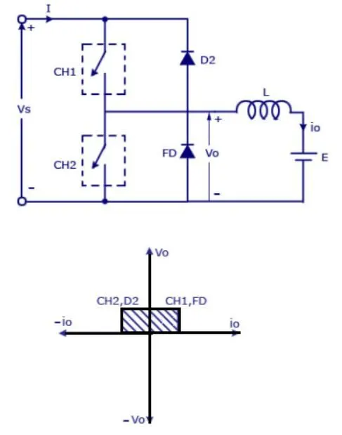
In the above circuit, CH1 and CH2 are 2 switches connected with a Vs, An inductance and an emf source are connected as load, and FD behaves as a freewheeling diode. when CH1 is turned on the current 'I' flows through the inductance load and towards the negative terminal of the source. Hence, charging the inductor during the process. This is called Forward motoring mode. When CH1 has turned off the inductor act as a battery storage device. When we turn on the switch CH2 the polarity of the inductor changes and output current Io flows from load to source which is also known as Regenerative braking mode.
In this chopper arrangement, the avg output voltage is always positive but the current can be positive or negative depending on the situation,
Simulink Model -
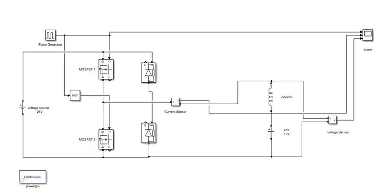
Blocks -
- Pulse Generator
- Voltage source
- MOSFET transistor
- Current measurement
- voltage measurement
- RLC block
- Scope
- PowerGUI
Description -
The Simulink model uses the MOSFET switch and a pulse generator for opening and closing switches 1 and 2. A NOT gate is provided to avoid the short-circuiting of the model. A current and voltage measurement block is used to measure the outputs of the circuit. A 12 v source and an inductor are used as a motor load for the circuit and a 24-volt source is provided. A power GUI block is used to Help with real-time Calculations.
Results -
Conclusion-
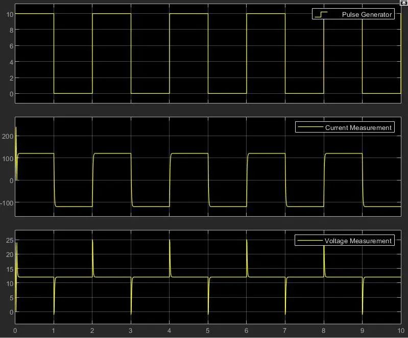
From the above results, we can see that the Voltage value remains positive while the current value is Switching between positive and negative. When MOSFET 2 is operating the current polarity is reversed while the voltage polarity remains unchanged.
The sudden surge in voltage values is due to a sudden change in current values between on and off switching. As the voltage is a change in the rate of current or `V = R.(di)/(dt)`
Model link - https://drive.google.com/drive/folders/1kMVWayjJT4FYm8heaTWlnXmTNwIJWkEG?usp=sharing
Operations of PM BLDC Motor
A Brushless DC Electric Motor (BLDC) is a type of electric motor that is powered by a direct current voltage supply and is commutated electronically rather than using brushes as in traditional DC motors.
The operation of a DC motor is fairly simple and can be explained below -
Permanent magnets are attached to the rotor in the DC motor. The current-carrying conductors, also known as armature windings, are found on the stator. Electrical commutation is used to convert electrical energy into mechanical energy.
The primary design distinction between brushed and brushless motors is the substitution of an electric switch circuit for the mechanical commutator. A BLDC motor is a type of synchronous motor because the magnetic fields generated by the stator and rotor revolve at the same frequency.
The Brushless motor does not have any current-carrying commutators. The field inside a brushless motor is switched through an amplifier which is triggered by the commutating device like an optical encoder.
The layout of a DC brushless motor can vary depending on whether it is in “Outrunner” style or “Inrunner” style.
- Outrunner – The field magnet is a drum rotor that rotates around the stator. This style is preferred for applications that require high torque and where high rpm isn’t a requirement.
- In runner – The stator is a fixed drum in which the field magnet rotates. This motor is known for producing less torque than the outrunner style but is capable of spinning at very high rpm.
Working -
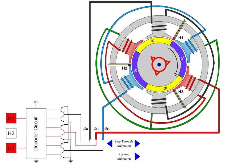
A BLDC motor operates on the same principle as a Brushed DC motor. The Lorentz force law states that a current-carrying conductor experiences a force whenever it is placed in a magnetic field. The magnet will feel an equal and opposite force as a result of the reaction force. The current-carrying conductor is stationary in the BLDC motor, while the permanent magnet is moving.
When the stator coils get power from the source, they transform into an electromagnet and begin to produce a consistent field in the air gap. Despite the fact that the source of power is DC, switching produces an AC voltage waveform with a trapezoidal shape. The rotor continues to rotate due to the force of interaction between the electromagnet stator and the permanent magnet rotor.
The matching windings electrified as North and South poles when the windings were switched as High and Low signals. The motor rotates because the North and South poles of the permanent magnet rotor align with the stator poles.
Advantages -
- Due to the lack of brushes, there is less overall maintenance.
- Thermal performance is considerably superior despite the smaller size.
- Lower electric noise generation and a wider speed range.
- It lacks a mechanical commutator, which causes issues.
- Because of the permanent magnet rotor, it has high efficiency and output power to size ratio.
- Due to the lack of brushes that limit the speed, the machine may operate at a high speed in both loaded and empty conditions.
- Brushless DC and induction AC motors have smaller motor geometries and are less in weight.
- Commutator systems have a long life span because they don't need to be inspected or maintained.
- Because of the stator's low inertia and carrying windings, it has higher dynamic responsiveness.
- Electromagnetic interference is reduced.
- Due to the lack of brushes, there is very little noise.
Disadvantages -
- These motors are expensive.
- The electronic controller needed to control this motor is costly.
- Complex drive circuitry is required.
- Additional sensors are required.