MODELLING AND RENDERING VINTAGE VESPA - SOLIDWORKS
MODELLING AND RENDERING VINTAGE VESPA
Introduction
I have selected the topic as vintage vespa because I was always fascinated to vintage model automotive, especially the design of Vespa gains my attention. Here in this design I have selected Piaggio Vespa 1975. Taking a glimpse on history of the model, we all know Vespa is a legendary scooter brand that is a part of the Italian conglomerate, Piaggio. Founded in 1946 in Florence, Vespa is one of the oldest two-wheeler brands in the world. The Vespa scooters are known for their design, simplicity and its ability to attract anyone towards it whenever it’s on the road.
Piaggio came to India with a collaboration to Bajaj to produce Vespa. After Bajaj, the Italian scooter brand tied up with LML Motors to manufacture and sell its scooters in India. However, this partnership ended in 1999. Piaggio launched the Vespa brand of scooters in India officially at the 2012 Auto Expo in Delhi.
Objective
The main objective of the project is to get skilled in Solidworks application through,
Modelling different parts for the Vespa.
Assemble them to the final model.
Perform some photo realistic rendering of the model.
Methodology
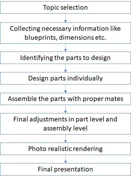
Explanation for parts
1.Body of Vespa
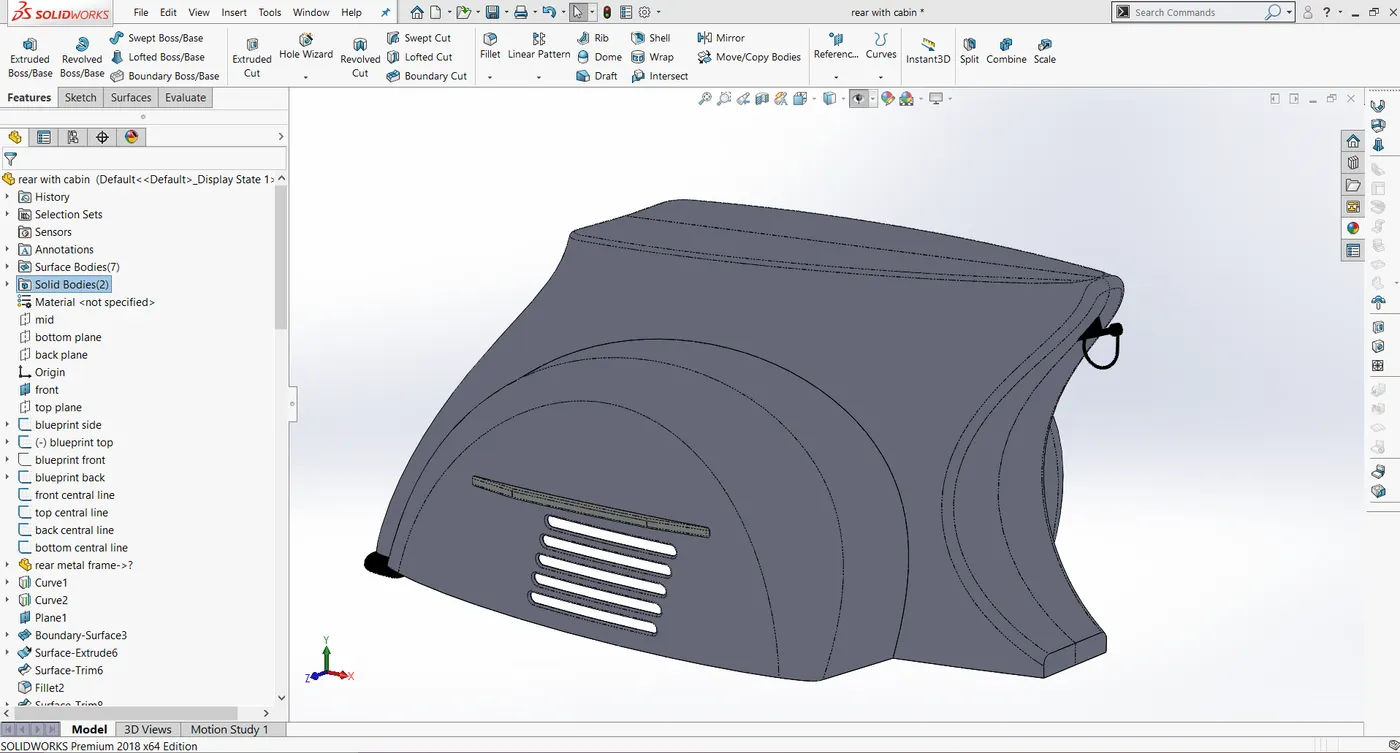
As like in every automobile, body becomes the aesthetic part of Vespa. It has a bulgy curved shape at the rear and flat wind shield structure at the front. Vintage vespa doesn’t had a dedicated chassis, instead it had the reinforcement within the body.
For the central walls of the rear body, boundary surface was created between 2 profiles with some direction curves. And used some sketch lines and surfaces to trim the unwanted regions. For the bulging side parts, surfaces were extruded with small draft angle and some boundary surfaces. Used extrude surfaces to fill the top and bottom regions. Then it was mirrored and knitted to form a solid. Applied fillets to the sharp edges. Use the shell feature to convert the body to thin sheet. Finally, used some features to further define its shape and add extra fittings.
(Features used: Sketch, Projected curves, Boundary surface, Surface trim, Surface knit, Extrude surface, Surface extend, Mirror, Sell, Delete face, Extrude, Chamfer, Fillet, Cut-Extrude, CrvPattern, Combine, Sweep, Revolve)
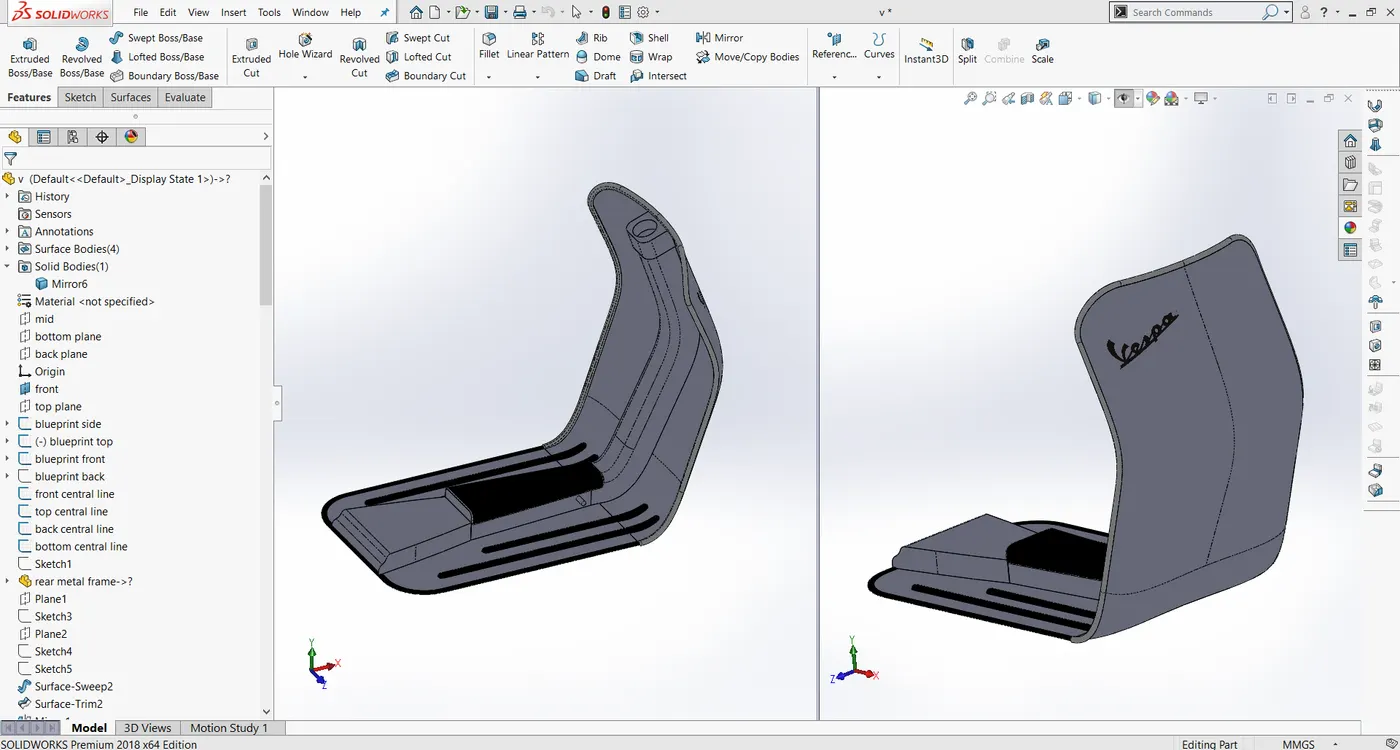
For the front part of the body some sweep surfaces and boundary surfaces were used. Sketch lines were used to trim the surfaces. Then the surface was thickened to form a solid body. Sketched some 3D curves by converting the edges and sweep some profile through the same to create groves.
2.Handlebar
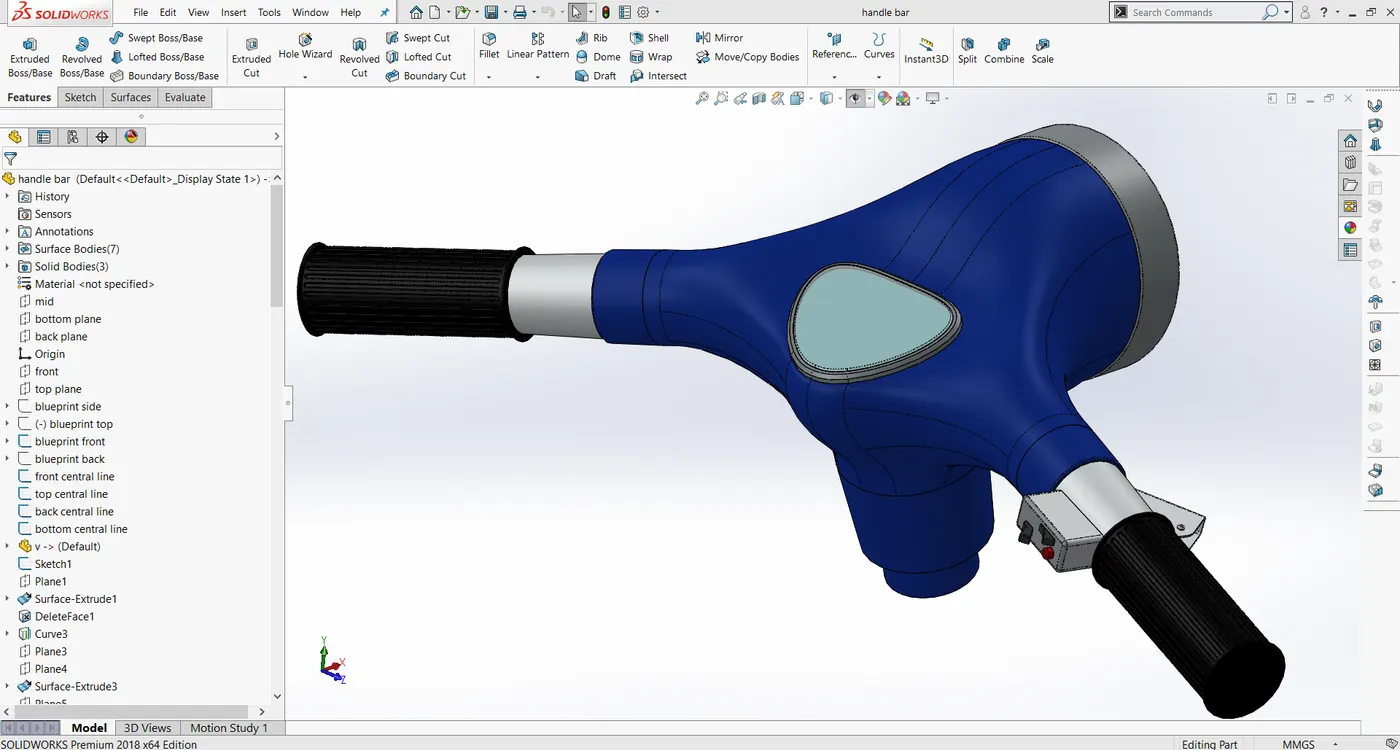
The function of handle bar is to balance and direct the vehicle. In Vespa the head lamp, speedometer and some control switches are integrated to the handlebar. The shape of handlebar was little challenging, were I used different surfacing techniques in design.
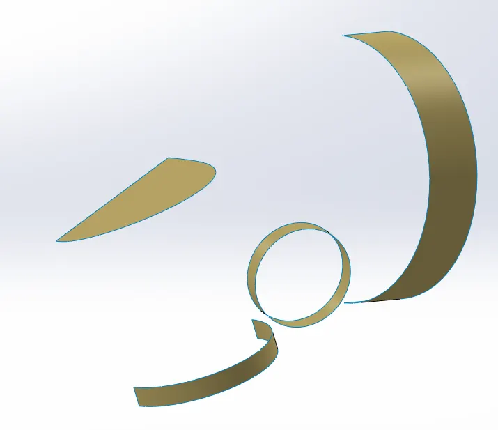
Designing handlebar was little bit challenging. In order to produce the shape, first I have created some surfaces for speedometer, headlamp casing and extended region to the right and bottom of the handlebar. These surfaces help as to define the boundaries. Then these surfaces were connected by using some boundary surfaces along some direction curves. Then the surfaces were knitted together and filled the remaining regions.
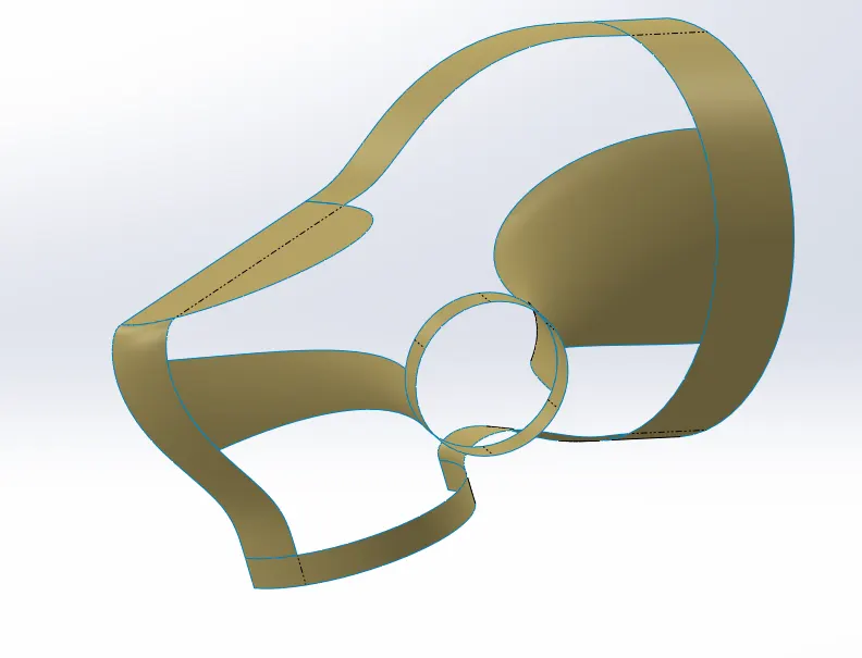
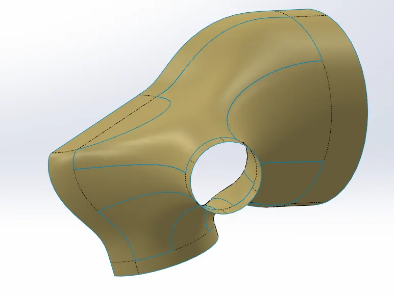
After defining the shape of the handlebar, then add detailing to complete the remaining parts. Features used for this part is mentioned below.
(Features used: Sketch, Projected curve, Surface extrude, Boundary surface, Delete Face, Split line, Surface fill, Surface knit, Surface plane, Mirror, Surface trim, Surface revolve, Boss-Extrude, Shell, Cut-extrude, Fillet, Surface offset, Thicken, Chamfer, Dome, Circular Pattern.)
3.Fork Cover
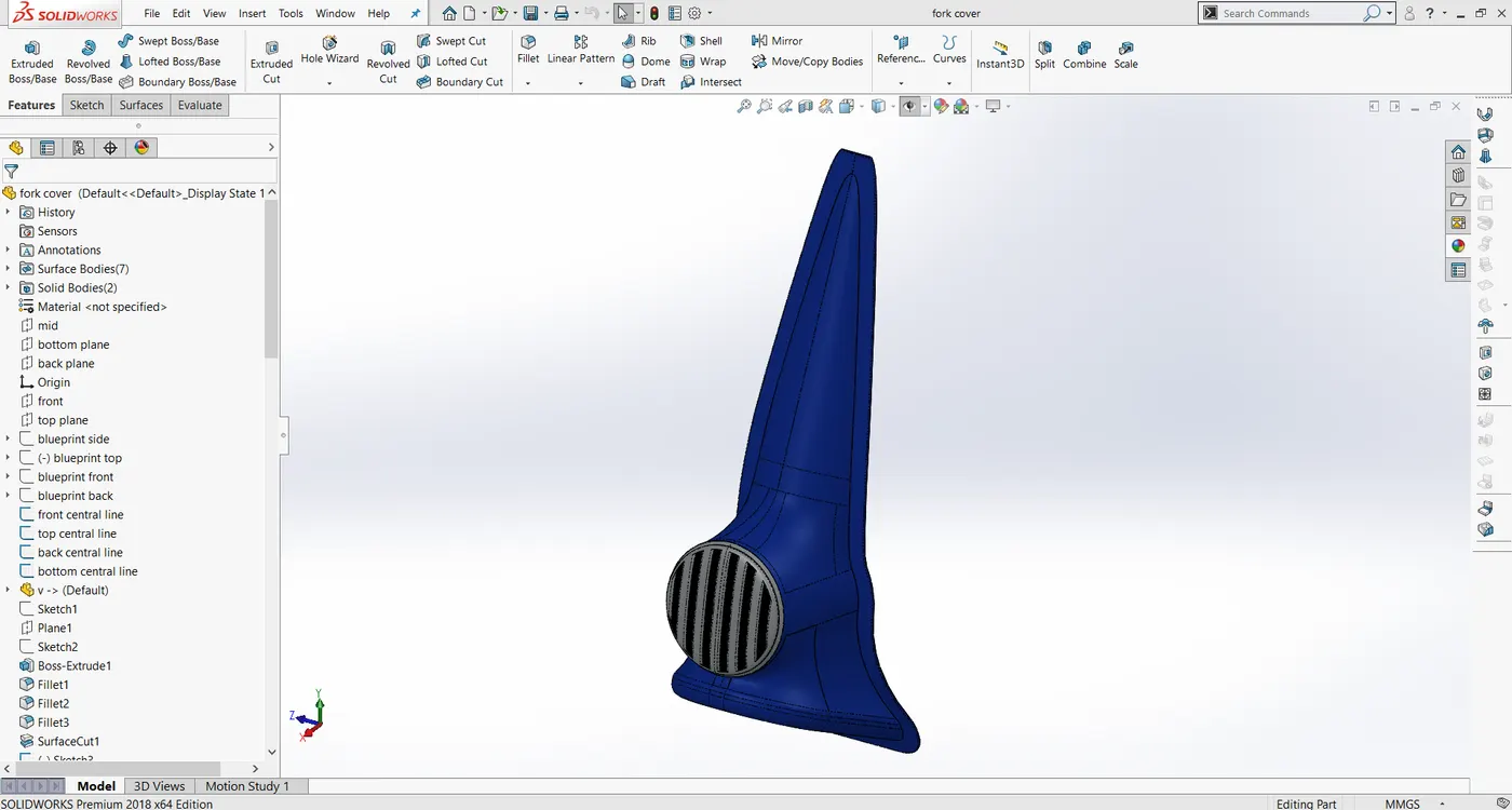
Fork cover Hides and protect the front fork. It is directly attached to the front body.
To design fork cover we have used surface of front body as a reference. The shape of fork cover was also challenging because it includes some smooth surface blend between some regular geometries like cylinder (at the nose). For that I have extruded a cylinder at the required position and trim the unwanted areas. Later, as like in handlebar I have created some boundary surfaces and connected them by filling the remaining areas.
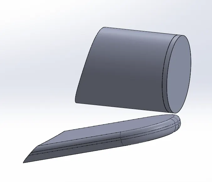
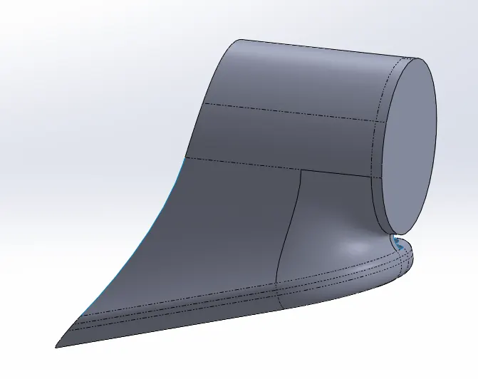
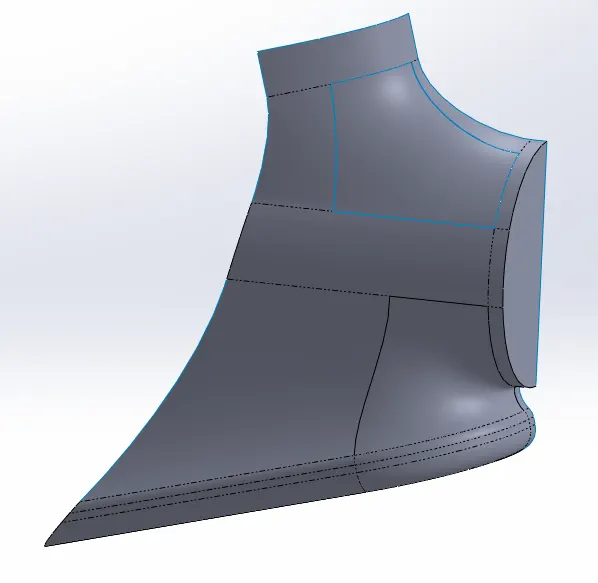
(Features used: Sketch, Boss-extrude, Surface-extrude, Fillet, Surface Cut, Split line, Delete face, Boundary surface, Knit surface, Surface Fill, Surface Offset, Thicken, Dome, Extrude cut, Body-Move, Split.)
4.Seat
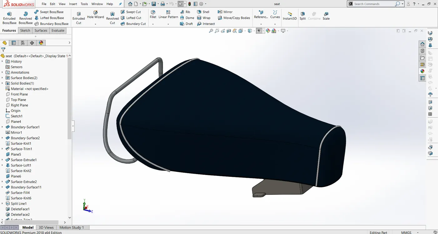
This model of vespa has split seat, that means rider and the pillion seats are independent. There is a dedicated spring system for the rider seat in order to reduce shocks.
(Features used: Sketch, Boundary surface, Mirror, Surface knit, Extrude surface, Fill surface, Split line, delete face, Thicken, 3D sketch, Sweep, Fillet, Freeform, Shell, Chamfer, Projected curve, Composite curve, Combine, scale.)
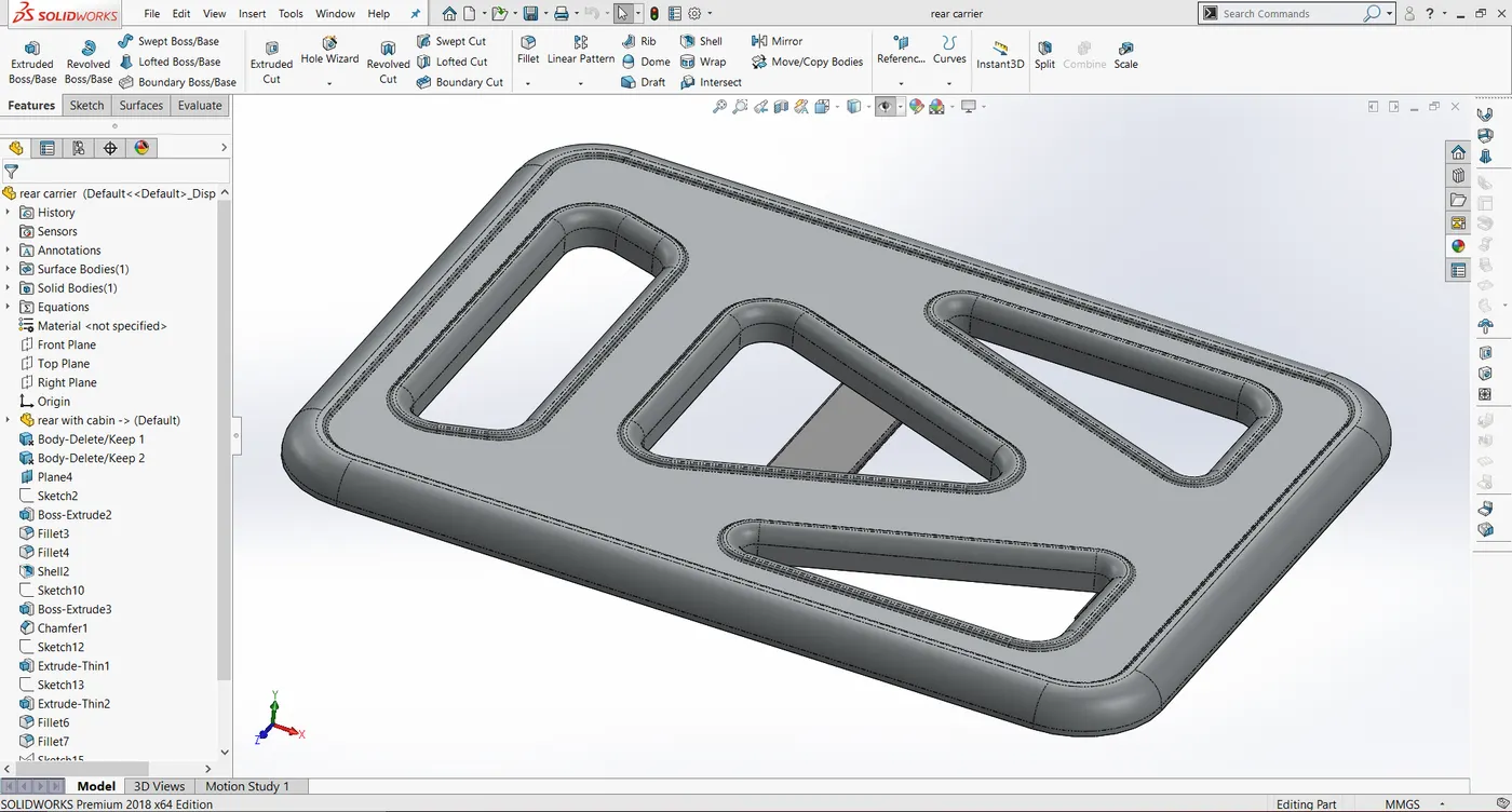
5.Carrier
If we remove the pillion seat of vespa then the space can be used for carrier. In this design I have modelled carrier instead of pillion seat.
(Features used: Sketch, Boss extrude, Shell, Chamfer, Fillet, Cut-extrude.)
6.Front Fender
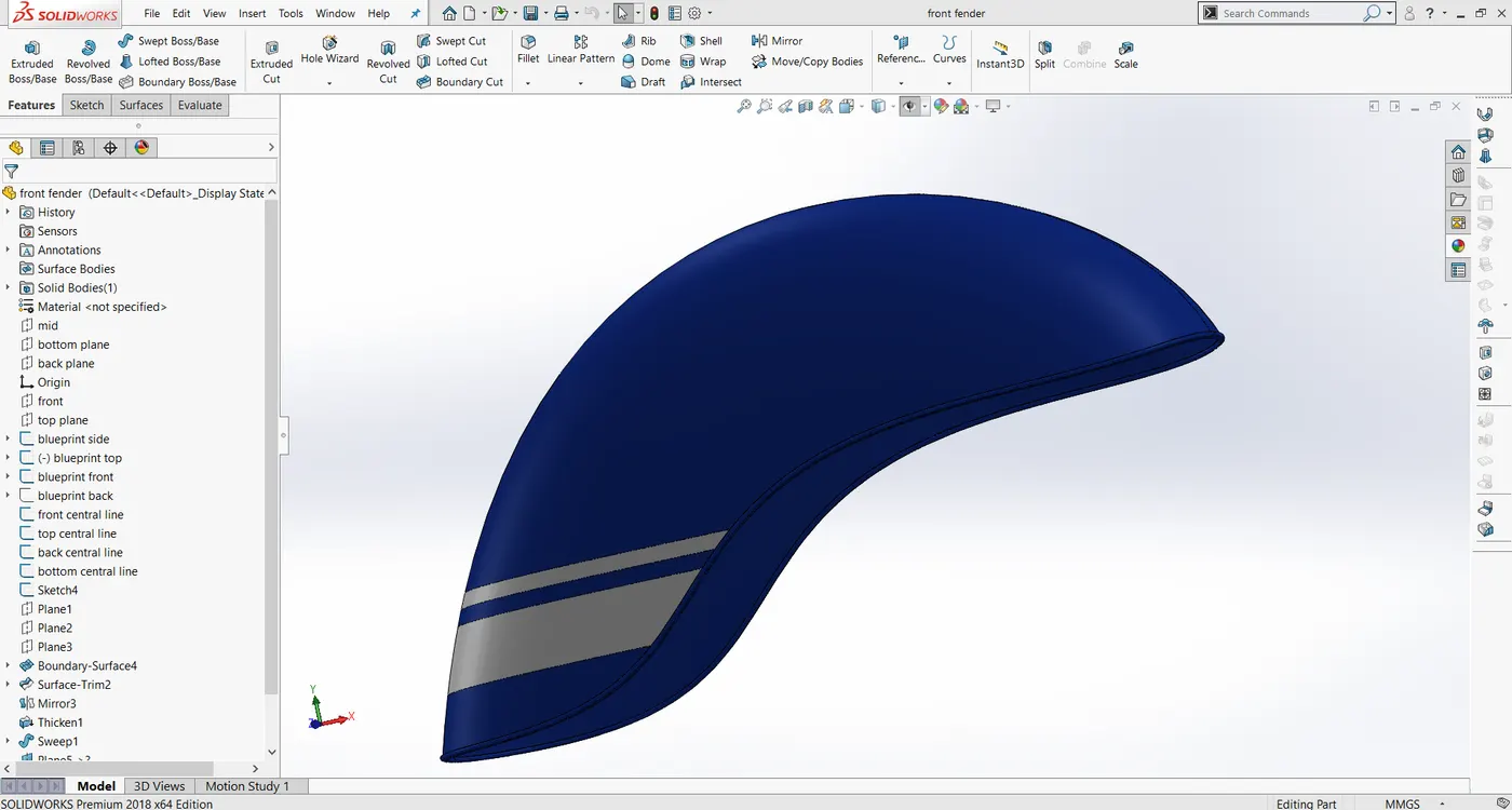
Fender covers the upper portion of wheel, in order to prevent the splashing of mud and other particles from the wheels.
(Features used: Sketch, Boundary surface, Mirror, Thicken, 3D sketch, Sweep, Split line.)
7.Front Suspension
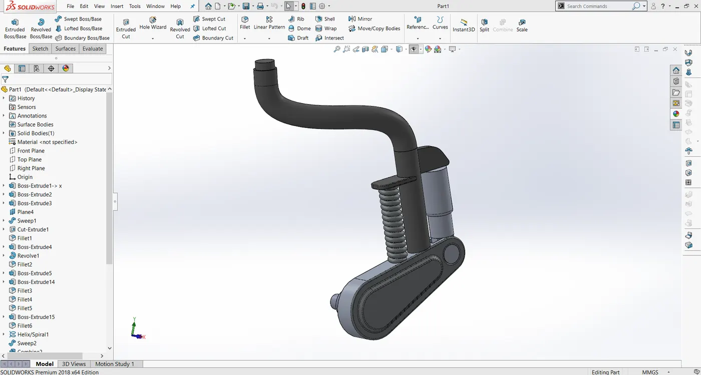
Front suspension of vespa include fork and the shock absorbers. This project aims the cosmetic version of vespa so that I have skipped the extension of fork that is not visible form outside.
(Features used: Sketch, Boss-extrude, Sweep, Cut-extrude, Helix, Fillet, Combine, projected curve.)
8.Wheel
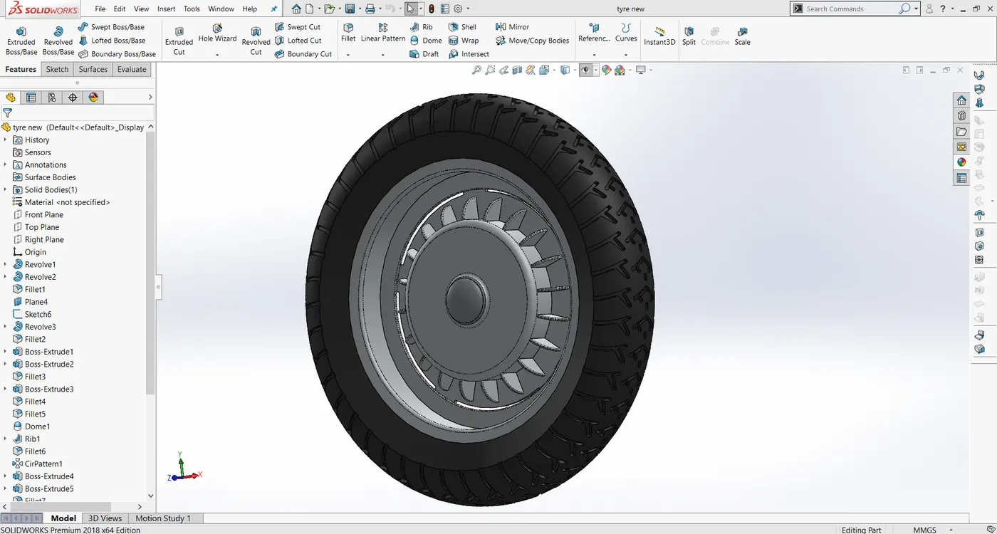
Wheels are the rotating elements that keep contact with the road. They are mounted to the axles which allow the rotational motion.
(Features used: Sketch, Revolve, Boss-extrude, Fillet, Dome, Rib, Circular pattern, Cut-extrude.)
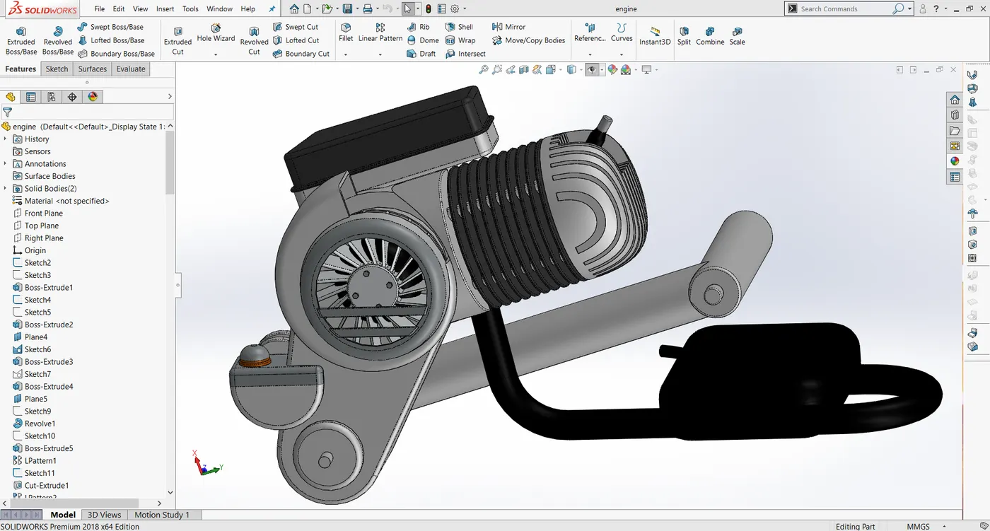
9.Engine
Engine is the prime mover of the vehicle. The combustion energy of the fuel is used to reciprocate the piston inside the cylinder, this reciprocating motion is converted to rotational motion with the help of crank and the connecting rod.
(Features used: Sketch, Boss extrude, Revolve, Linear Pattern, Fillet, Cut extrude, Helix/Spiral, Loft, Shell, Circular pattern, Combine, Scale, Split, Move body, Sweep.)
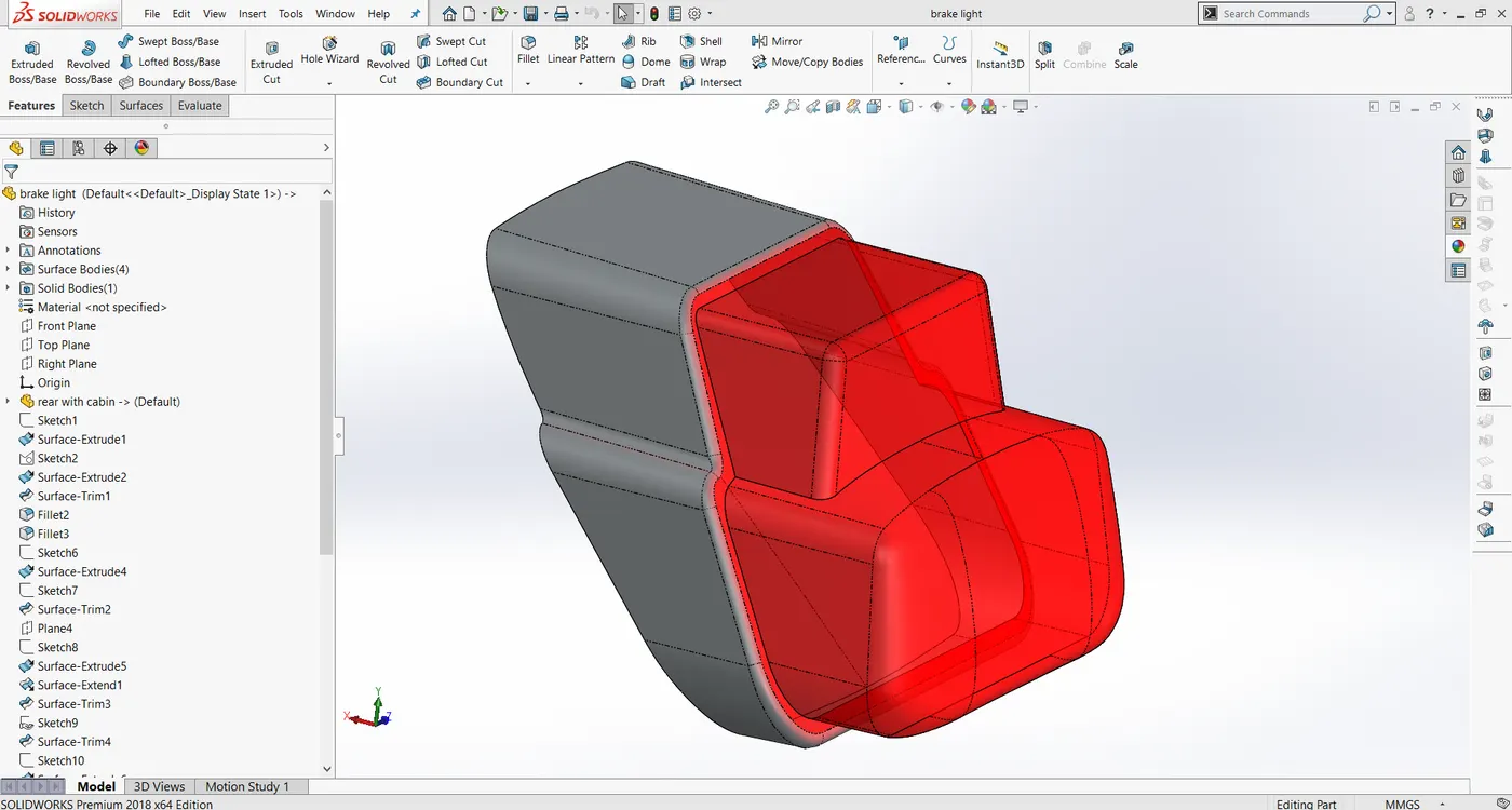
10.Brake light
Brake light is directly mounded to the rear body of vespa. It indicates brake engagement.
(Features used: Sketch, Surface extrude, Surface trim, Boundary surface, Fill surface, Mirror, Surface knit, Fillet, Delete face.)
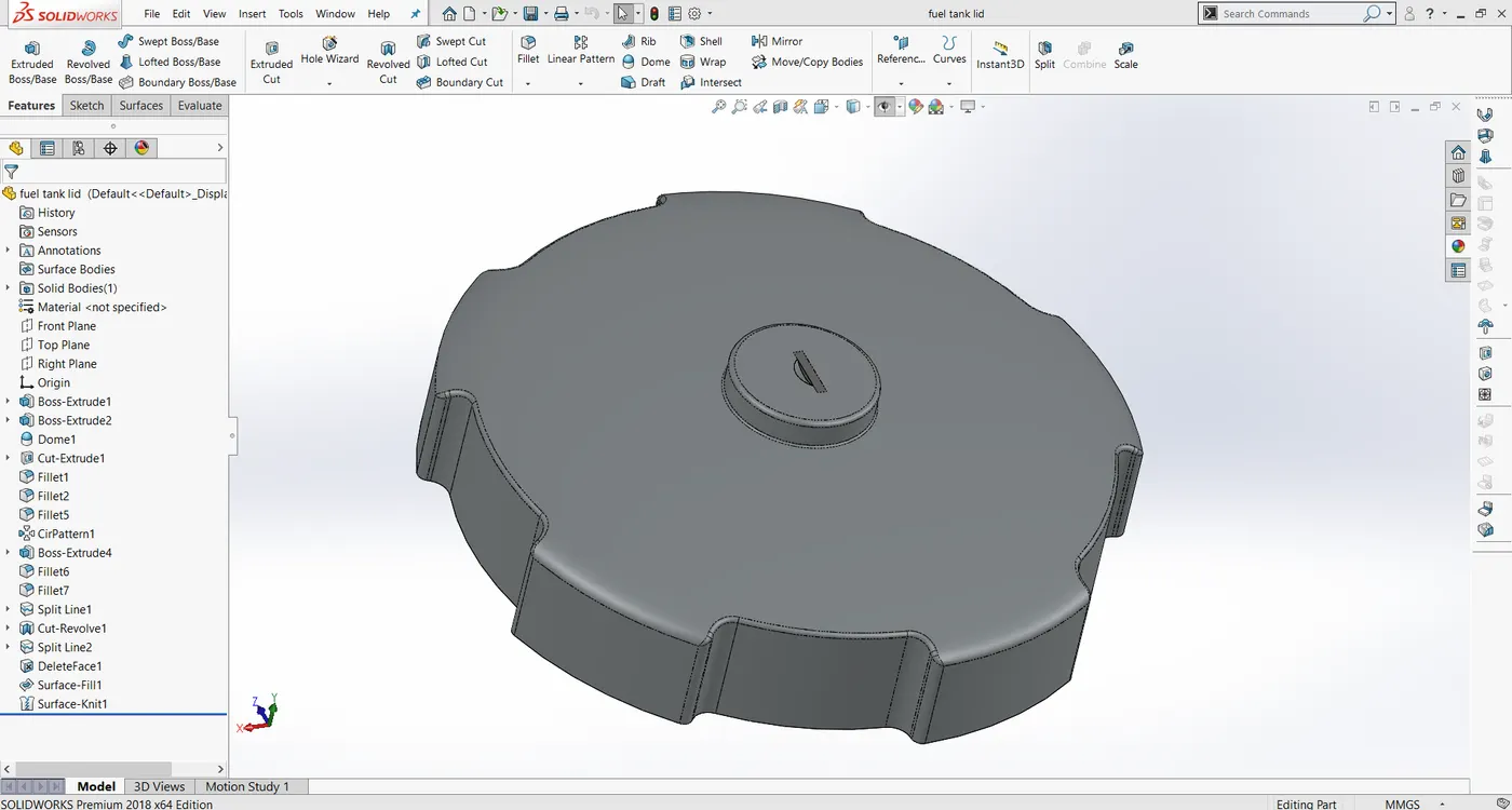
11.Gas Tank Lid
Gas tank lid in vespa are placed in between the rider and pillion seats. After inserting the key, lid can be opened and closed by rotating the lid itself.
(Features used: Sketch, Boss extrude, Cut extrude, Circular pattern, Dome, Split line, Delete face, Surface fill, Surface knit, Fillet.)
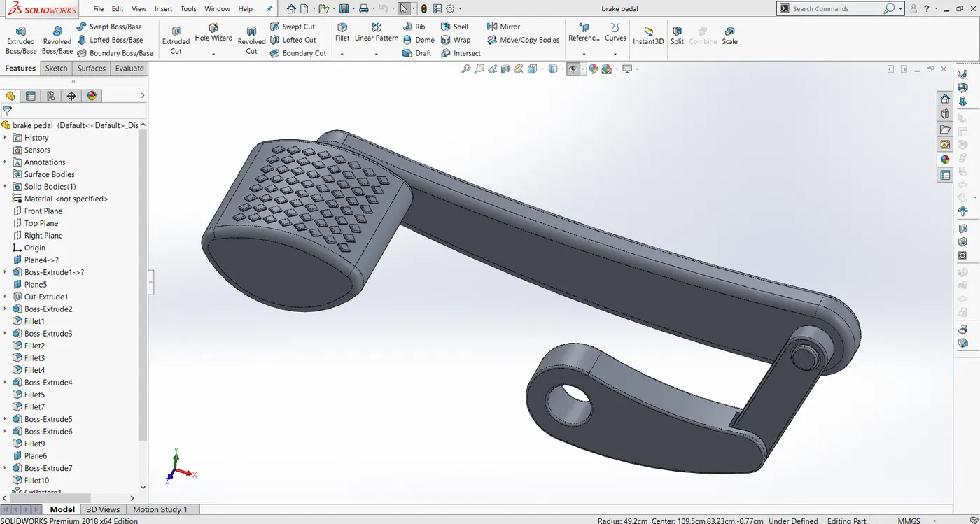
12.Brake Pedal
Brake pedal is a movable link used to engage back bake if required, and it can be activated by right foot.
(Features used: Sketch, Boss extrude, Cut extrude, Fillet, Circular pattern, Linear pattern, Combine.)
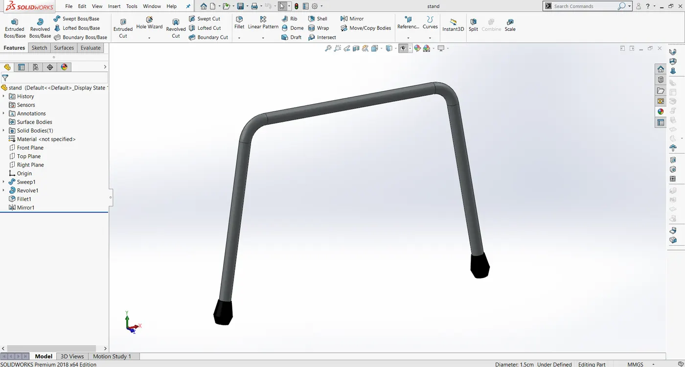
13.Stand
Stand is used to support and balance the vehicle at stationary condition. In vintage vespa there is only central stand, and it is hinged directly to the bottom of the body.
(Features used: Sketch, Sweep, Revolve, Fillet, Mirror.)
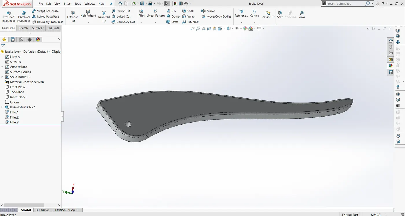
14.Brake/Clutch Lever
They are used to engage clutch or brake respectively according to the requirements. They are hinged to the Handlebar and can be operated by fingers.
(Features used: Sketch, Boss extrude, Fillet.)
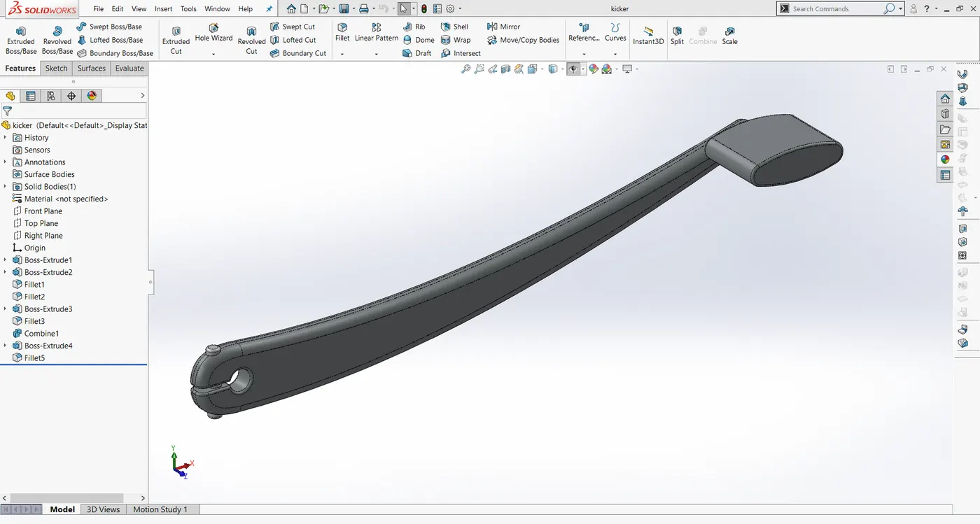
15.Kicker
Kicker is used to rotate the crank shaft which translate the motion to the piston by externally in order to begin the engine cycle.
(Features used: Sketch, Boss extrude, Fillet, Combine.)
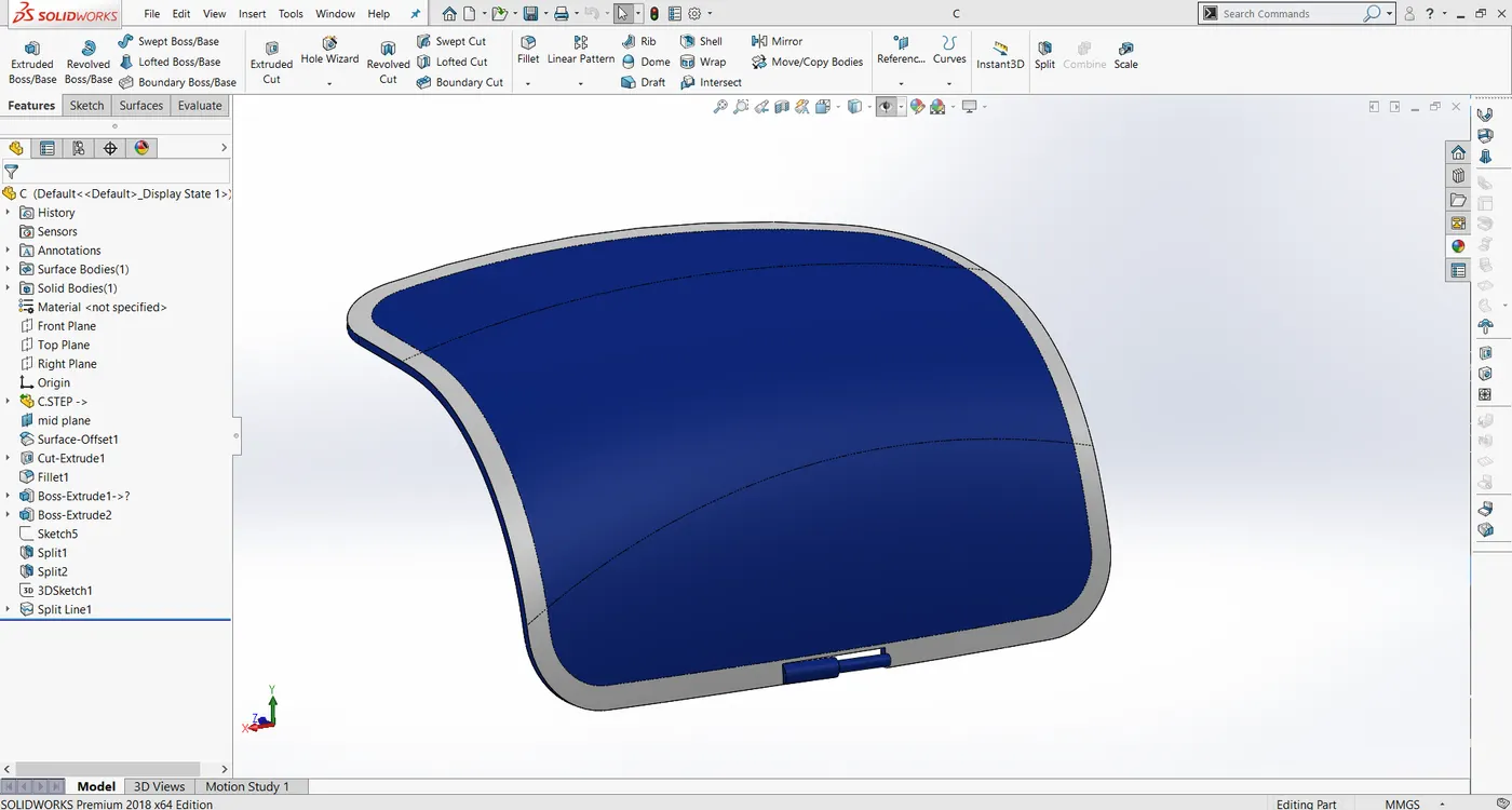
16.Cabin Door
Cabin door covers the cabin space in the vehicle. In this model it is a part spited directly from the body and assembled to the same using a hinge.
(Features used: Surface offset, Cut extrude, Fillet, Boss extrude, Split, Split line.)
17.Shock Absorber Rear (Sub assembly)
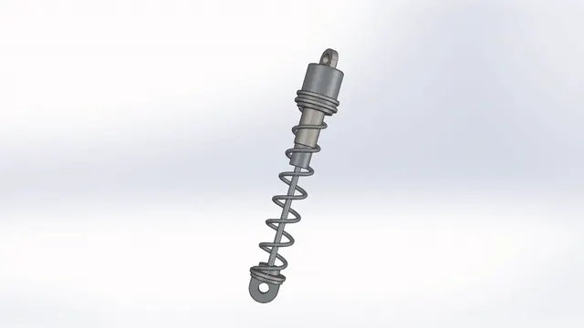
In this design model it is a sub assembly which consist of a piston part, cylinder part and the spring. It is a dynamic model, were spring get compressed and released by the movement of piston and cylinder parts.
(Features used: Sketch, Boss extrude, Fillet, Surface extrude, Surface Sweep, Body-Delete/Keep, Surface cut, Reference planes, Mate conditions.)
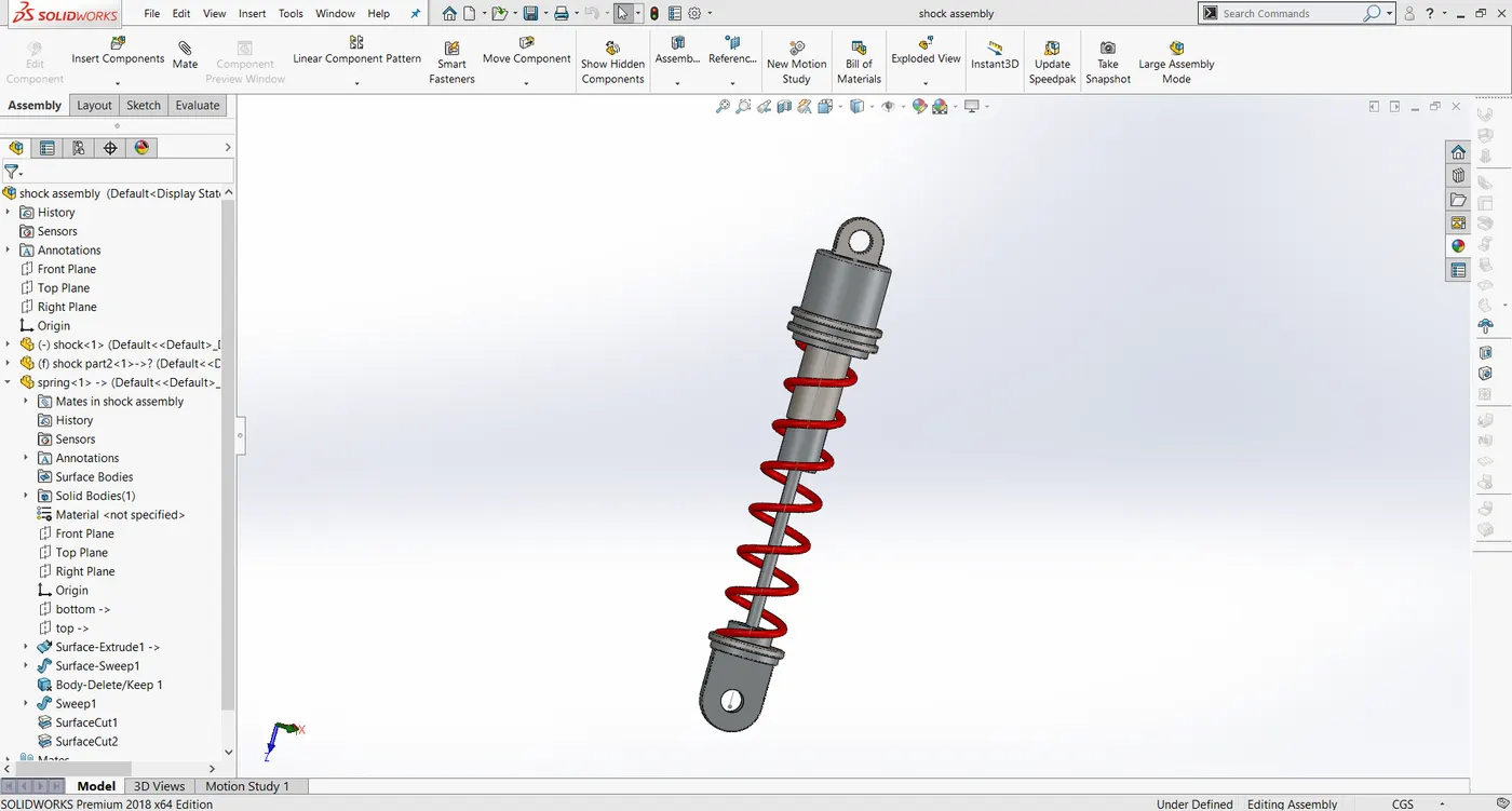
Animated Shock assembly
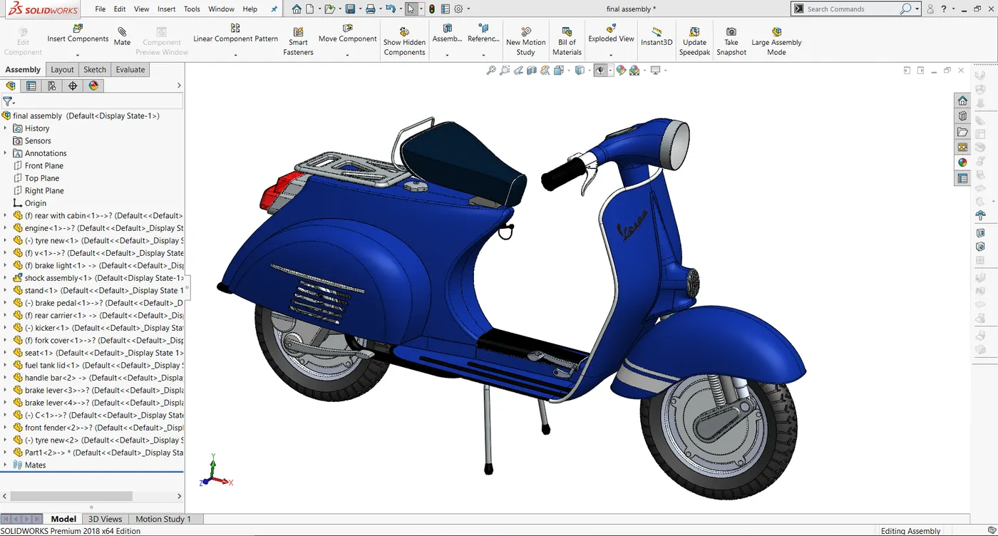
Assembly
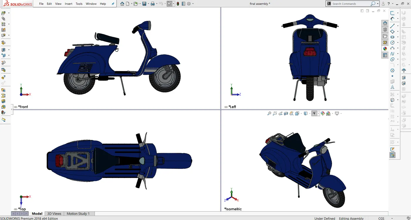
There are 20 parts in the final assembly. They are assembled using proper mate conditions. Mate conditions used for this assembly are: Coincident mate, Distance mate, Parallel mate, Angle mate.
Different views in assembly
Rendering
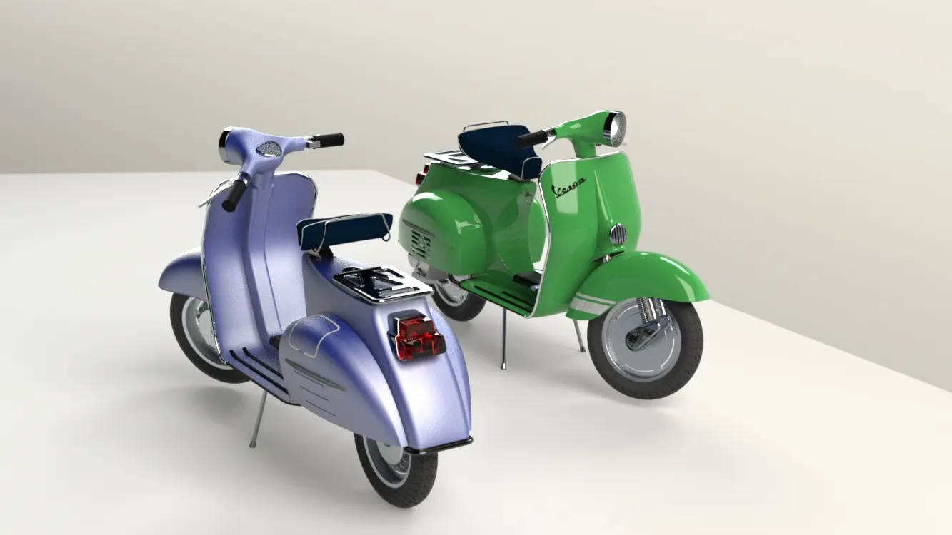
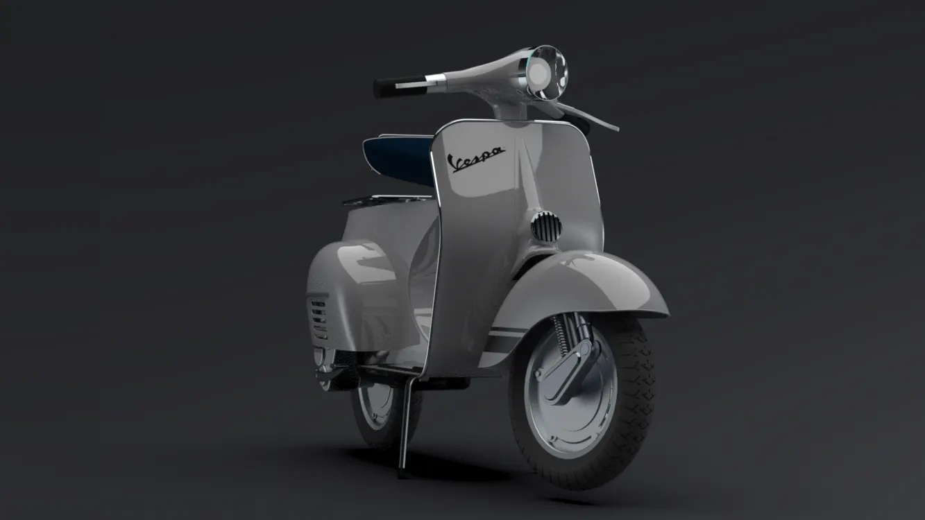
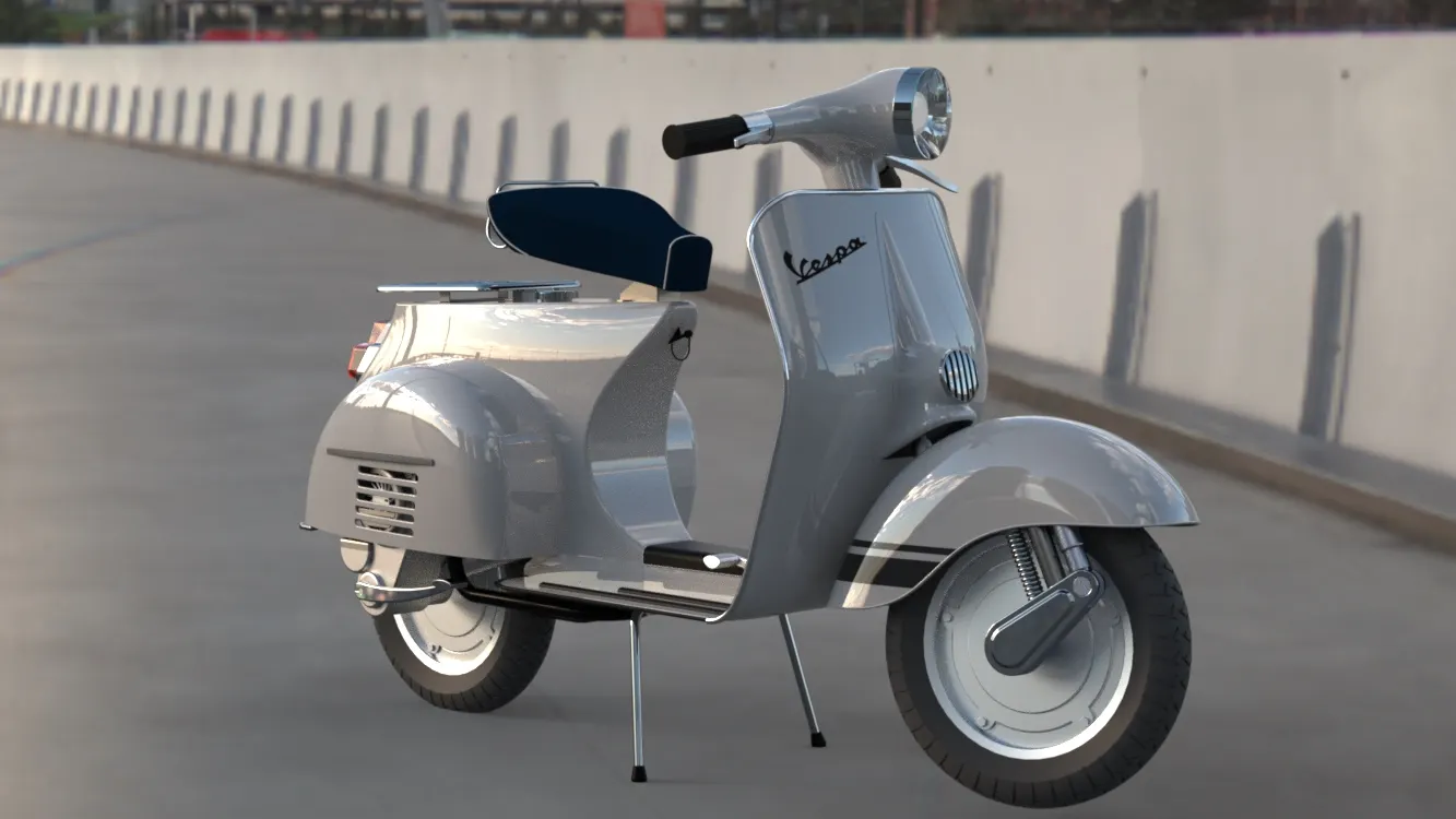
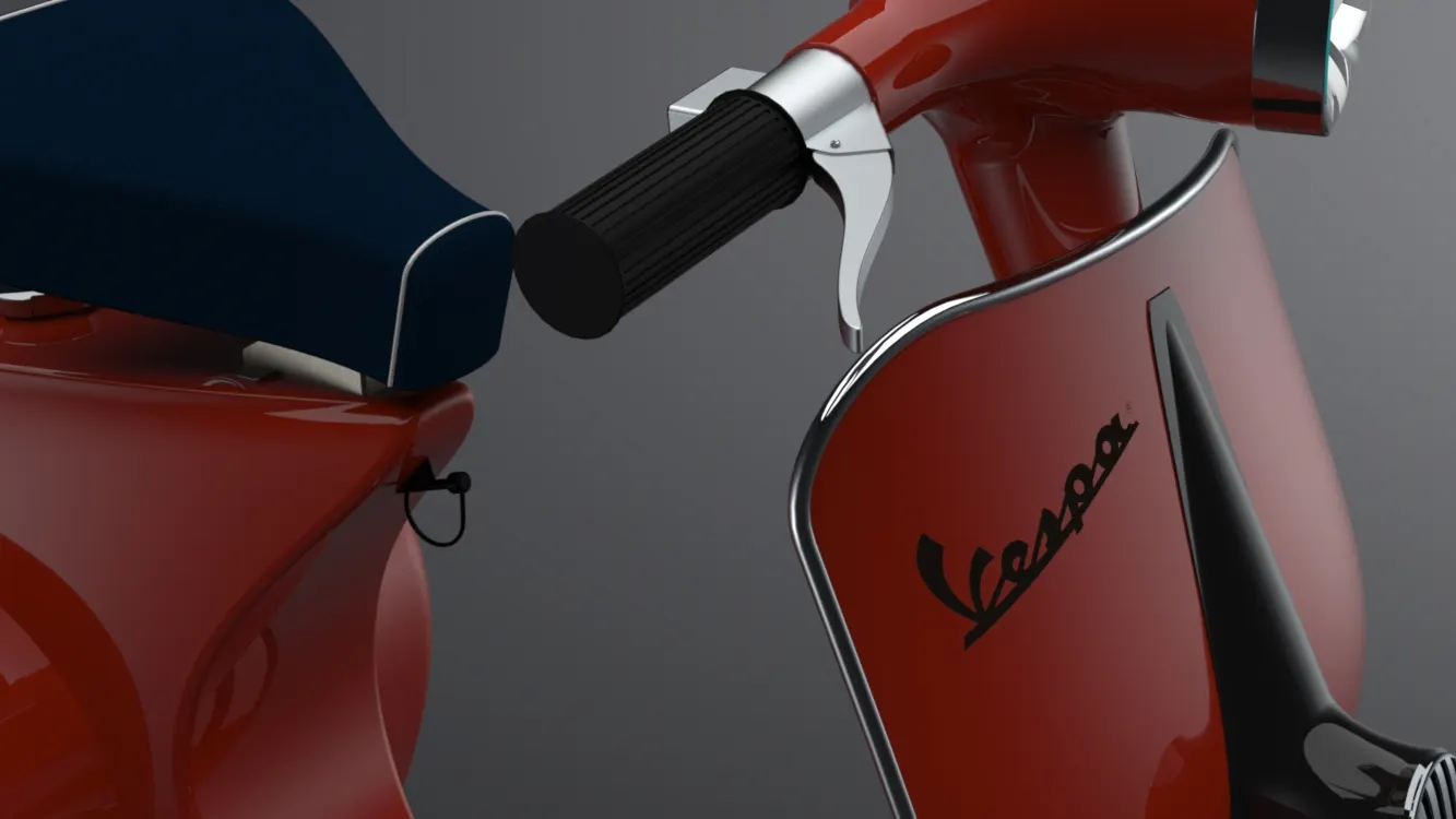
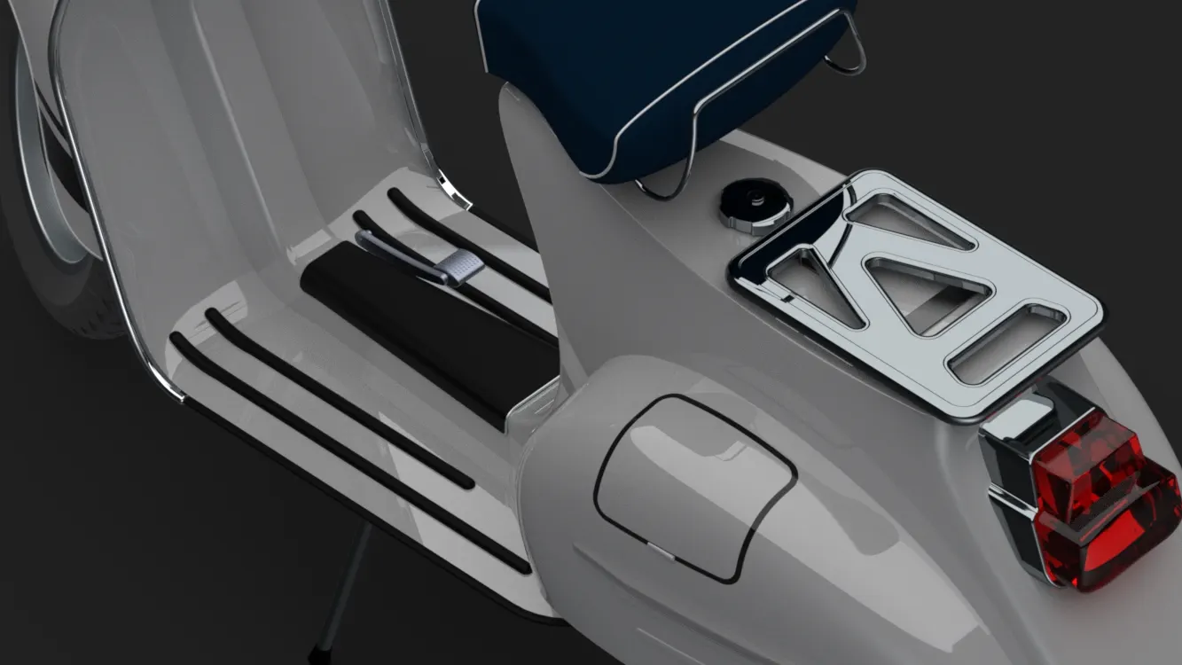
Rendering includes applying proper appearance, environment, light conditions, adjusting the position of model, position of camera etc. For rendering I have used Photoview360 (Solidworks Add-ins.) and Solidworks Visualize 2018.
Using Photoview360
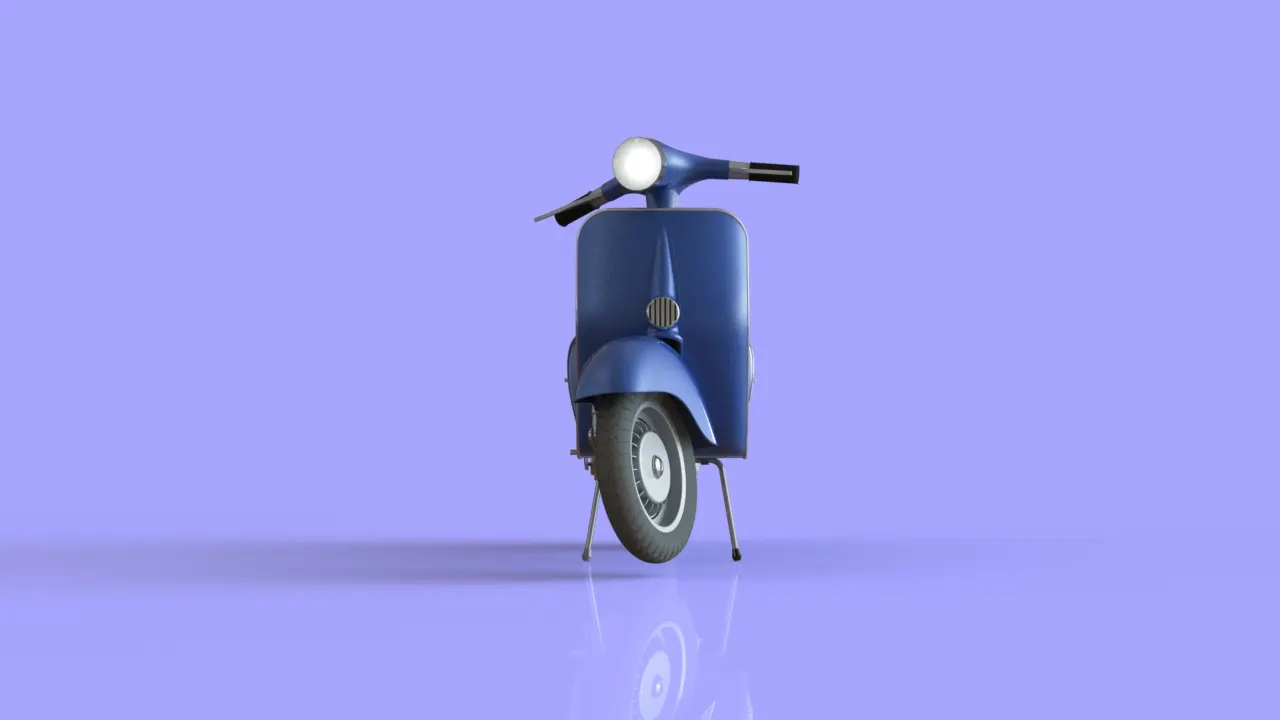
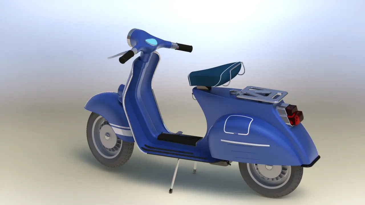
Using Solidworks Visualize 2018
Result and Conclusion
Modelled different parts for Vespa
Assembled them using proper mate conditions
Applied appearance, environment, lightings, decals and rendered the model in Photoview360 and Solidworks Visualize.
Reference
Skill-lync tutorials
YouTube channels and videos
Spring animation: https://www.youtube.com/watch?v=WYxdJtdHqWI&t=1146s
Image mask file for Decal: https://www.youtube.com/watch?v=5ENrLpfT8x4
Vespa restoration: https://www.youtube.com/watch?v=O1wROxBRpbo
Solidworks Visualize Shortcuts: https://www.youtube.com/watch?v=F642hUQx0uE
Blending instead of fillets: https://www.youtube.com/watch?v=irMK9Jwc1f8