Advanced Sheet Metal Design Using NX Cad Challenge_2_Box Assembly
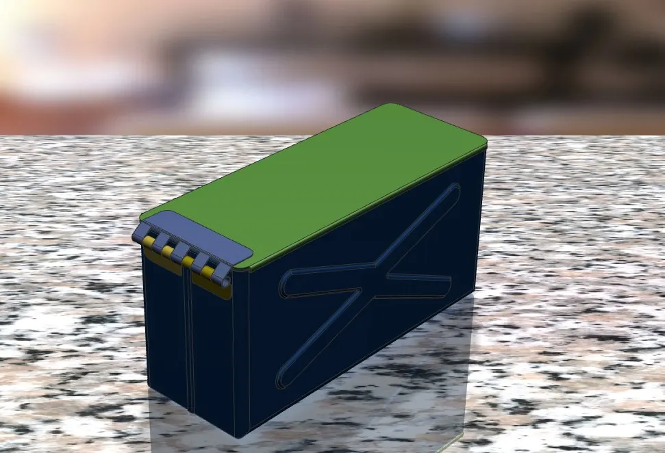
Sheet metal Box Assembly Designed by using NX cad
OBJECTIVE :-
To design the sheet metal Box assembly by using NX CAD software with Suitable command to Achieve the final product.
INTRODUCTION :-
NX CAD is one of the powerful design tool. To design various product from 2D to 3D various platforms like modelling ,sheet metal and surfacing etc.. with Suitable commands to achieve the final product.
Based on this I going to design a product named as BOX assembly Design
DESIGN METHDOLOGY :
| Select file in the NX CAD |

| Select Sheet metal Platform and saved with Suitable name |
| Select XY plane to draw the sketch |
| Tab is Created with Reference Sketch |
| Flanges is created at required edges |
| Hem flanges is created at required edges |
| Corners of Sides has been closed properly by using closed corner command |
| Add flanges at sides of the tab |
| Done mirror of the object as per the Dimension |
| Dimple is created remaining two sides of an flange |
| One more dimple created at the bottom of the face |
| Bead is created at 4 positions near the previous dimple |
| Datum plane is created at certain height for create top door |
| Sketch is created on Datum palne |
| Tab is created for the previous sketch with thickness 2mm |
| Again hem flange is created on all the corners by using hem flange with length of 3mm |
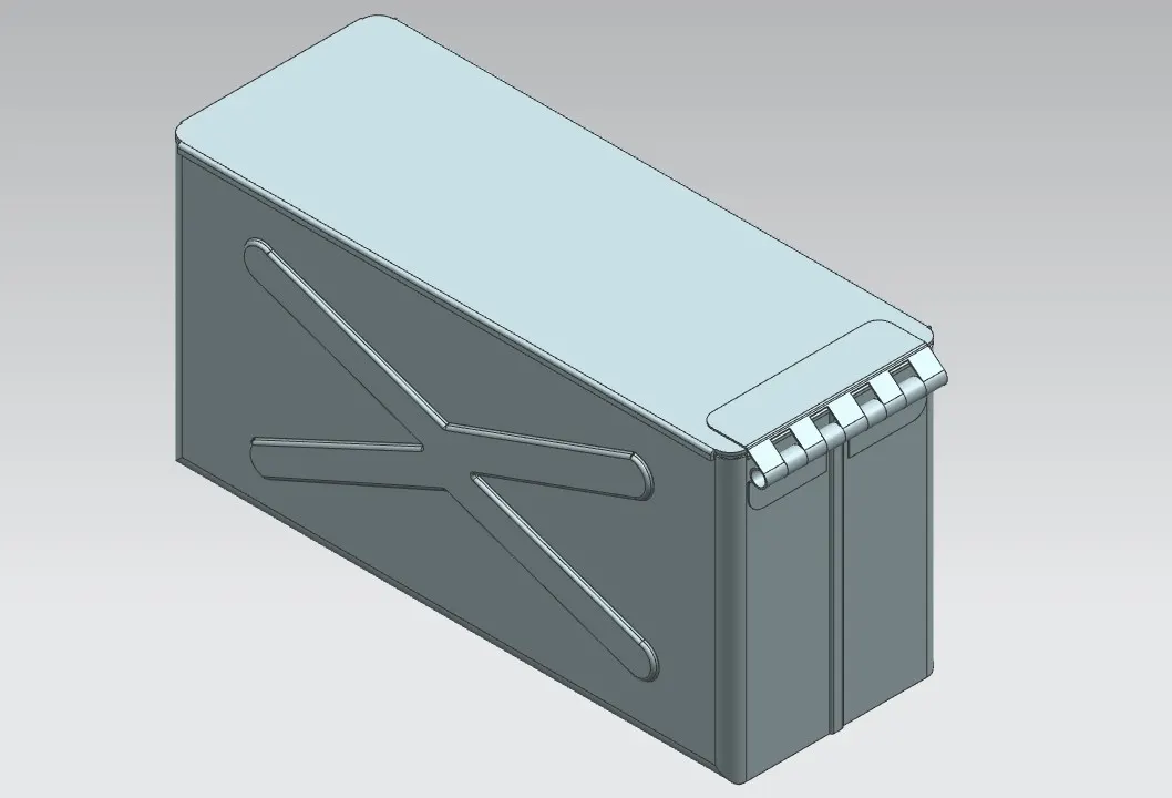
| Hinge type model is created on one of the sides of the box for opening and closing of the door |
DESCRIPTION :-
SKETCH :- It’s a basic command to draw 2D model
TAB :- It’s a command to add parameters of a sketch
FLANGE :- It’s an operation to extend of an sheet metal with reference to one of the edge of an Tab.
MIRROR IMAGE :- This feature is used to create same replica of an object wit respect to axis selection.
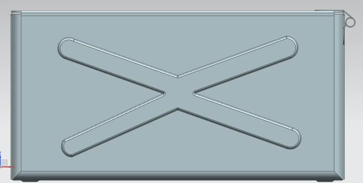
DIMPLE :- It is an type of projection command of a particular shape .with reference to sketch with certain depth.
BEADS :- It is also type of projection to deform the shape at a certain point with reference to sketch and also giving strength to the body.
DATUM PLANE :- This feature is used to draw a sketch at certain distance by selecting the datum plane.
NORMAL CUTOUT :- This feature is used to remove unwanted material with respect to sketch drawn on the face.
IMAGES :-
FRONT VIEW :-
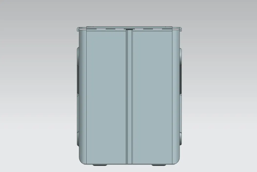
SIDE VIEW :-
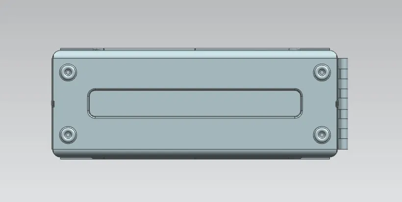
BOTTOM VIEW :-
ISOMETRIC VIEW :-
CONCLUSION :- This challenge I came to know about the application of various commands and selection of planes to achieve the final product.