FINAL INDEPENDENT PROJECT
FINAL INDEPENDENT PROJECT REPPORT
DESIGNING OF CAM PROFILES FOR ENGINEERING APPLICATIONS USING MATLAB
INTRODUCTION
A cam is a rotating machine element which gives reciprocating or oscillating motion to another element
known as the follower:
- The cams are usually rotated at uniform speed by a shaft.
- The follower motion is predetermined and depends on the shape of the cam.
- Complicated output motion which are otherwise difficult to achieve can be easily produced with the
help of cam and follower mechanisms. - Cam are used in internal combustion engines, automatic attachment of machineries, machine tools such
as automatic lathe machine, paper cutting machines, textile machineries etc. - Cam and follower have a line contact and constitute a higher pair.
- The motion is imparted from the cam to the follower via direct contact.
Necessary elements of a cam mechanism are
1. A driver member - the cam
2. A driven member - the follower
3. A frame which supports the frame and guides the follower.
TYPES OF CAMS
Cams are classified according to:
1. Shape
2. Follower movement and
3. Manner of constraint of the follower
1. According to Shape
a) Wedge and flat cams b) Radial or disc cams c) Spiral Cams d) Cylindrical Cams e) Conjugate Cams f) Globoidal Cams g) Spherical Cams
2. According to follower movement
a) Rise Return Rise (R-R-R) b) Dwell Rise Return Dwell (D-R-R-D) c)Dwell Rise Dwell Return Dwell (D-R-D-R-D)
3. According to Manner of Constraint of the Follower
a) Pre loaded Spring Cam b) Positive drive Cam C) Gravity Cam
TYPES OF FOLLOWER
1. According to the surface in contact
a) Knife edge follower b) Roller follower c) Flat faced or mushroom follower d) Spherical faced follower
2. According to the motion of the follower
a) Reciprocating or translating follower b) Oscillating or rotating follower
3. According to path of motion of the follower
a) Radial follower b) Off-set follower
CAM TERMINOLOGIES
1. Base Circle : It is the smallest circle tangent to the cam profile (contour) drawn from the centre of rotation of a radial cam.
2. Trace Point : It is a reference point on the follower to trace the cam profile such as the knife edge of a knife edged follower and centre of the roller of a roller follower.
3. Pitch curve : It is the curve drawn by the trace point assuming that the cam is fixed, and the trace point of the follower rotates around the cam.
4. Prime circle : The smallest circle drawn tangent to the pitch curve is known as the prime circle.
5. Pressure angle : The pressure angle, representing the steepness of the cam profile, is the angle between the normal to the pitch curve at a point and the direction of the follower motion.
6. Pitch point : It is the point on the pitch curve at which the pressure angle is maximum.
7. Pitch circle : It is the circle passing through the pitch point and concentric with the base circle.
8. Lift or stroke : It is the maximum travel of the follower from its lowest position to the topmost position.
9. Angle of ascent : It is the angle through which the cam turns during the time the follower rises.
10. Angle of dwell : It is the angle through which the cam turns while the follower remains stationary at the highest or lowest position.
11. Angle of descent : It is the angle through which the cam turns during the time the follower returns to the initial position.
12. Angle of action : It is the total angle moved by the cam during the time, between the beginning of rise and the end of the return of the follower.
FOLLOWER TERMINOLOGY
In studying the dynamic characteristics of the follower for the different motion schemes, the
following nomenclature is used
• H = Total follower displacement during the rise or fall interval under consideration In the case of a
pivoted follower, this is the total angular displacement of the follower link, ΔΔθL,during the particular
interval.
• T = Total time period for the rise or fall interval under consideration.
• t = Time into rise or fall interval that defines the instantaneous follower properties.
• β = Rotation angle of cam during the rise or fall interval under consideration (deg).
• Φ = Angle into rise or fall interval that defines the instantaneous follower properties (deg).
• ω𝒄𝒂𝒎 = Speed of the cam (degrees per time).
• Δ R = Magnitude of the instantaneous follower displacement at time t or cam angle β In the case of a
pivoted follower, this is analogous to the instantaneous angular displacement of the follower link, ΔΔθL.
• v = Magnitude of the instantaneous follower velocity dR dt In the case of a pivoted follower, this is
analogous to the rotation of the follower link, ωL.
• a = Magnitude of the instantaneous follower acceleration dv/ dt.
FOLLOWER MOTION SCHEMES
The follower, during its travel, may have one of the following motions
1. Uniform or constant velocity motion
2. Uniform or constant acceleration and retardation
3. Harmonic motion
4. Cycloidal motion
1. Uniform Velocity Motion : It is characterized with a straight line displacement diagram because velocity is uniform.

FIG. The constant velocity displacement diagrams along with velocity and acceleration curves.
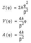
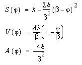
2. Uniform Acceleraton Motion : Constant acceleration motion during a rise or fall sequence produces the smallest possible values of acceleration for a given rise and time interval The displacement diagram for a rise or fall interval is divided into two halves, one of constant acceleration and the other of constant deceleration The
shapes of each half of the displacement diagram are mirror image parabolas.
When
,
When
,
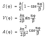
3. SIMPLE HARMONIC MOTION : A cam mechanism with the basic curve will impart simple harmonic motion to the follower. The velocity diagram at h indicates smooth action. The acceleration, as shown at i, is maximum at the initial position, zero at the mid-position, and negative maximum at the final position.
4. CYCLOIDAL MOTION : The dynamic equation for cycloidal motion are:

Construction of Displacement diagram
The shape of the cam depends on the desired motion of the follower A scaled displacement
diagram of the follower is required to construct the actual cam profile, i e the actual shape of the cam
Analytical Method
The equations presented in the previous slides can be used in conjunction with a spreadsheet
or other equation plotting package to complete the displacement diagram
Graphical Method
Graphical construction of a displacement diagram is an alternative method to generating a
displacement diagram to scale Such a construction can be accomplished by following a set procedure
which are shown in the next few slides for constant acceleration, simple harmonic and cycloidal motion
schemes of the follower
OBJECTIVE : The prime objective of this project is to design precise cam geometries which are widely used in many engineering aplications such as Automobiles, Powerplants, Industrieal machinery etc. using analytical approach along with MATLAB.
MOTIVATION : To faciliate friction-free movement of different mechanical equipments and machines.
METHODOLGY : In this project we are going to design a cam profile for any specefic application. We consider the input parameters as per the defined applications such as for a wall clock mechanism the input parametes such dwell time , rise and fall height, rotational speed of shaft is quite different from the cam follower used in IC Engines. On the basis of the input, we are going to design the cam profile and its displacement curve.
PROBLEM :
Consider for a mechanical system, we are going to design a cam follwer roller assembly. A cam is to give the following motion to a Knife-edged follower. Given, the line of stroke is offset 5 mmvfrom the axis of the cam shaft. The radius of the base circle of cam is 40 mm. Rotational speed of cam shaft 60 rpm. The designed trajectory of the follower is as follows:
| Follower Motion | Height (in mm) | Time (in sec) | Follower action |
| SHM | 20 | 10 | Rise |
| Dwell | 0 | 2 | Remain constant |
| Cycloid | 10 | 10 | Rise |
| Dwell | 0 | 3 | Remain constant |
| 3-4-5 Motion | 15 | 15 | Fall |
| Dwell | 0 | 4 | Remain constant |
| Cycloid | 15 | 10 | Fall |
| Dwell | 0 | 6 | Remain constant |
Design the cam profile and follower displacement using the MATLAB considering above situation.
CODE STRUCTURE :
% Task Cam Profile And Follower Displacement Diagram
clear
close all
clc
syms t
r_base = 20;
w = pi/30;
%SHM
h_shm = 20;
fy_shm = 10*w;
th_shm = (0:60)*(pi/180);
s_shm = (h_shm/2)*(1 - cos(pi*t/fy_shm));
v_shm = diff(s_shm,t);
s_shm = subs(s_shm,t,th_shm);
v_shm = subs(v_shm,t,th_shm);
fy = th_shm;
v = v_shm;
%DWELL
th_dwell = w*2;
th_dwell_t = linspace(fy(end),fy(end)+th_dwell,15);
s_dwell = s_shm(end).*ones(1,15);
fy = [th_shm th_dwell_t];
s = [s_shm s_dwell];
v_d1 = zeros(1,15);
v = [v_shm v_d1];
%CYCLOIDAL
h = 10;
fy_cyc = w*10;
th_cyc = linspace(0,fy_cyc,61);
th_cyc_t = th_dwell_t(end) + th_cyc;
s_cyc = s(end) + (h)*((t/fy_cyc) - (1/(2*pi))*sin(2*pi*t/fy_cyc));
v_shm = diff(s_cyc,t);
s_cyc = subs(s_cyc,t,th_cyc);
v_cyc = subs(v_shm,t,th_cyc);
s = [s s_cyc];
fy = [fy th_cyc_t];
v = [v v_cyc];
%DWELL
th_dwell = w*3;
th_dwell_t = linspace(fy(end),fy(end)+th_dwell,15);
s_dwell = s(end).*ones(1,15);
fy = [fy th_dwell_t];
s = [s s_dwell];
v_d2 = zeros(1,15);
v = [v v_d2];
%3-4-5
h = -15;
fy_345 = w*15;
th_345 = linspace(0,fy_345,91);
th_345_t = fy(end) + th_345;
s_345 = s(end) + (h)*(10*(t/fy_345).^3 - 15*(t/fy_345).^4 + 6*(t/fy_345).^5);
v_345 = diff(s_345,t);
s_345_r = subs(s_345,t,th_345);
v_345_r = subs(v_345,t,th_345);
s = [s s_345_r];
fy = [fy th_345_t];
v = [v v_345_r];
%DWELL
th_dwell = w*4;
th_dwell_t = linspace(fy(end),fy(end)+th_dwell,15);
s_dwell = s(end).*ones(1,15);
fy = [fy th_dwell_t];
s = [s s_dwell];
v_d3 = zeros(1,15);
v = [v v_d3];
%CYCLOIDAL
h = -15;
fy_cyc = w*10;
th_cyc = linspace(0,fy_cyc,61);
th_cyc_t = th_dwell_t(end) + th_cyc;
s_cyc = s(end) + (h)*((t/fy_cyc) - (1/(2*pi))*sin(2*pi*t/fy_cyc));
v_shm = diff(s_cyc,t);
s_cyc_r = subs(s_cyc,t,th_cyc);
v_cyc_r = subs(v_shm,t,th_cyc);
s = [s s_cyc_r];
fy = [fy th_cyc_t];
v = [v v_cyc_r];
%DWELL
th_dwell = w*6;
th_dwell_t = linspace(fy(end),fy(end)+th_dwell,15);
s_dwell = s(end).*ones(1,15);
fy = [fy th_dwell_t];
s = [s s_dwell];
v_d4 = zeros(1,15);
v = [v v_d4];
plot(fy*180/pi,s)
Dis = s+r_base;
tha = fy*180/pi;
x = Dis.*cosd(tha);
y = Dis.*sind(tha);
x_base = (r_base).*cosd(tha);
y_base = (r_base).*sind(tha);
%pressure angle
al_inline = atand(v./(w*Dis));% for inline knife
e = 5;% offset
r_f = 5;% roller radius
al_offset = double(atand((v./w).*(Dis./(e.^2 +Dis.^2 -e.*(v./w)))) - atand(e./Dis)); %offset knife
al_roller = atand(v./(w.*(r_f+Dis))); %roller
figure(1)
plot(fy*180/pi,s)
grid on
axis([0 400 -5 33])
xlabel('Cam Angle (Deg)');
ylabel('Follower Displacement (mm)');
title('Follower Displacement Graph');
%cam profile in cartesian plane
figure(2)
plot(x,y,'-r',x_base,y_base,'--k')
title('Cam Profile (Cartesian Graph)');
%cam profile in polar coordinate
figure(3)
polar(tha*(pi/180),Dis)
title('Cam Profile (Polar Graph)');
grid on
axis square
t = 0:5:60;
th = w*t*180/pi;
T = ((pi/180)*tha./w)';
A = double([T,tha',s',v',al_inline',al_offset',al_roller']);
disp('Time Cam angle Disp. Vel. PA(Inline) PA(Offset) PA(roller) ')
disp(A)
SOURCE CODE SNIPS
RESULTS :
Displacement Curve
CAM PROFILE in cartesian plane
CAM PROFILE in polar plane
OUTPUT CALCULATION:
The above code divides into 2 different parts. One is plotiing of displacement curve and second is ploting desired cam profile. In the first part, the programme is futher segmented into different parts as per the different motion performed by the follower. The programme initialize some variables such as h, fy, th, s, v which are updated after each and every motion. There is constant angular speed = w of the shaft. From these variables, the output displacement is calculaletd using the follower motion equations. These values of displacement is finally stored in an array s which is fianlly plotted against fy. The 2D displacement curve is a graph between follower diaplacement vs cam angle (Φ).
In the second part, the cam profile is calculated in cartesian and polar plane respectively. The cam profile is obtain by adding s (calculate in part 1) with base radius. The black dash is a circular profile of base circle while the red color figure represents the cam profile. Using polar function, the same is plotted on a polar plane for better understanding.
| Position | Cam Angle, Φ (in degree) | Follower Displacement, s (in mm) |
| Intially at rest | 0 | 0 |
| SHM | 60 | 20 |
| Dwell | 72 | 20 |
| Cycloid | 132 | 30 |
| Dwell | 150 | 30 |
| 3-4-5 | 240 | 15 |
| Dwell | 264 | 15 |
| Cycloid | 324 | 0 |
| Dwell | 360 | 0 |
UTILITY : Majority of this are used to prooduce better and precise cam profiles used in delicated mchanical apllications. Some of the applications are discussed below:
APPLICATIONS OF CAM AND FOLLOWERS
- Cam and follower are widely used for operating inlet and exhaust valve of I C engine.
- These are used in wall clock.
- These are used in feed mechanism of automatic lathe Machine.
- These are used in paper cutting machine.
- Used in weaving textile machineries.
- The cam mechanism is a versatile one. It can be designed to produce almost unlimited types of motioning the follower.
- It is used to transform a rotary motion into a translating or oscillating motion.
- On certain occasions, it is also used to transform one translating or oscillating motion into a different translating or oscillating motion.
- Cams are used in a wide variety of automatic machines and instruments.
- The certain usuages of cam and followers that includes textile machineries, computers, printing presses, food processing machines, internal combustion engines, and countless other automatic machines, control systems and devices. The cam mechanism is indeed a very important component in modern mechanization.
VALIDATION : We can validate the same by solving th same problem using Graphical/Theoritical approach.
CONCLUSION :
The above study is one of basic and gold standard method for designing shaft for different purposes. This method also coincides with the theoritical results. Such a method is used to design highly precise and sophisticated cam follower assembly. This method for multi-purpose application developement of shafts is accurate too.
Mention the errors faced while programming
* Most of the common errors are typo errors.
* Difficulty in undertsnding the data in logic to solve the problem.
* Error in polar function.
Steps taken to overcome those errors.
* Uses the MATLAB doc for correct syntax.
* Refer to the book for more knowledge on Cam and follower terminolgy.
* Take guidance of MATLAB docs.