FINAL INDEPENDENT PROJECT
Objective: To create the ASR locomotive 3D model with assembly and rendering.
History of ASR Locomotive:
The ASR H Class were built as T class locomotives with modifications for use at the Melbourne Hump Yard. They were fitted with additional equipment for their duties, including extra weight for traction, "manual power control" to allow low-speed operation, and an accurate low-speed speedometer.
The H class was delivered as T413 to T417 but was reclassified before entering service. The class rarely left Melbourne due to their excessive weight, until being approved to operate on the same lines as the N class in January 1987. All were included in the sale of V/Line Freight to Freight Victoria in May 1999 and passed with the business to Pacific National in August 2004.
Pacific National sold three of the H class to the Ettamogah Rail Hub in 2015. Two of those were on-sold to 707 Operations in 2018. H4 was scrapped in 2020, while H1 had had its long hood cladding removed and was stored in North Dynon between 2020 and April 2022, when it was transferred to the Seymour Railway Heritage Centre as part of a long-term restoration project.
ORIGINAL DESIGN REFERENCE:
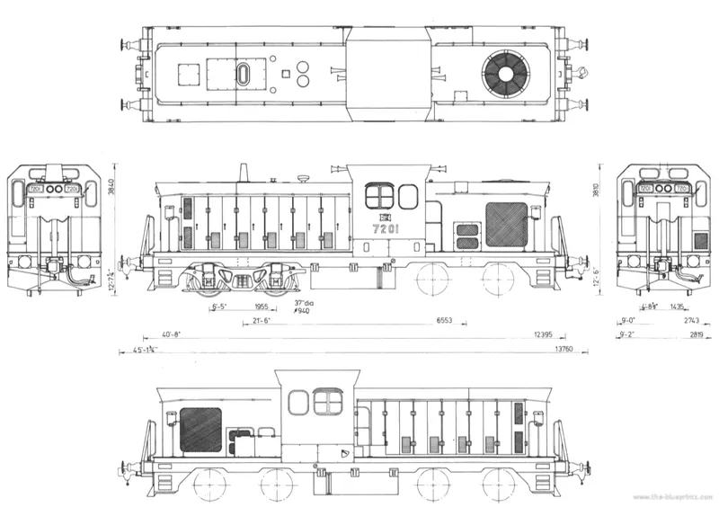
The locomotive original blueprints were openly available after the model was scrapped from the Australian rail services and I found them in Blueprints.com.Only the basic attributes standardly considered for the design of the locomotive are used by me :
- Basic Dimensions i.e., Height, length, width, and Gague width (width between wheels for positive traction )
- No.of wheelsets
- Type of bogie system
- Turbo fan design and placement
- Guide rails placement
- Dampers
LIST CORE OF PARTS(Sub assemblies):
- Bogie Assembly
- Traction Motor Assembly
- Compressor set Assembly
- Fuel Tank
- Frame
- Centre Body
- Horn
- Turbofan
- Sandbox
Let's discuss each sub-assemblies in detail and the type of features used in the modelling process.
1. Bogie Assembly:
A bogie is a structure underneath a railway vehicle body to which axles and wheels are attached through bearings. The term “bogie” is used in British English, while a “wheel truck”, or simply “truck” is used in American English. The overall term is “running gear”, which covers bogies as well as vehicles with two, or more axles without any bogies. In this case, these axles are directly fitted to the vehicle body via guiding devices and springs, and for very low speeds even without springs.
Running gears serve a number of purposes:
• support of the rail vehicle body
• stability on both straight and curved tracks
• Provide ride comfort by absorbing vibration, and minimizing centrifugal forces when the train runs on curves at high-speed
• minimizing generation of track irregularities and rail abrasion.
- Radial steering principles: To reduce the forces between rails and wheels, several radial steering design principles for wheelsets are applied. The aim of these designs is to reduce wear and noise caused by low steering forces. Designs with connected wheelsets and wheelsets connected to the vehicle body are based on lever systems that act on the wheelsets via the axle boxes. The Bogie steering system used in our bogie is the Transverse type.
- Selection of practical examples:
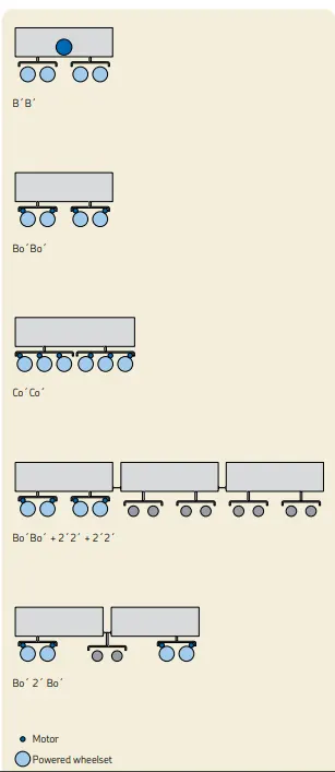
• B´B´ two bogies or wheel assemblies under the unit. Each bogie has two powered axles, connected by driving rods or gears.
• Bo´Bo´ each bogie has two individually driven powered axles. 75% of all modern locomotives(as well as the power cars of self- propelled trains) are configured as Bo´Bo´.
• Co´Co´s two bogies or wheel assemblies under the unit. Each bogie has three individually-driven, powered axles (i.e., via traction motors).
• Bo´Bo´ + 2´2´ + 2´2´ multiple units, first unit: two bogies, each bogie has two individually-driven powered axles; second and third unit: two bogies, each bogie with two non-powered axles.
• Bo´ 2´ Bo´ articulated vehicle: first and the last bogie has two individually-driven powered axles / middle bogie (Jacobsdesign) with two non-powered axles. - THE TYPE OF BOGIE SYSTEM THAT WE USED IS Bo´Bo´ SYSTEM. refer to the below image for a detailed understanding.
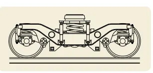
- Type of Bogie Wheelset design reference: Link arm suspension with one primary helical spring on top of the axle box assembly, which is designed as a yoke, enabling vertical dismounting of the wheelset assembled with the axle box for easier maintenance. This design was applied for the French bogie type Y32 for Corail coaches and is similar to the Italian bogie Fiat Y0270S and Spanish bogie CAF-GC. 1 and is widely used in Europe, for instance in the Alstom TVG bogies.
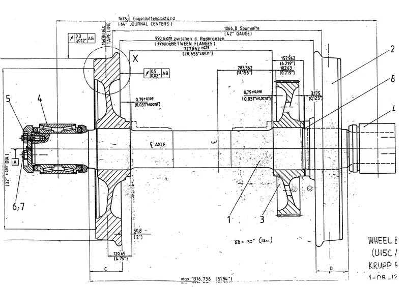
- Wheel Set design Reference:
- LIST OF COMPONENTS IN BOGIE ASSEMBLY:
- Axle box
- Axle cap
- Axle shaft
- Equalizer beam
- Axle Link
- Axle secondary spring
- Primary coil spring
- Beam link
- Wheel
- Bogie frame
- Bogie frame plate
- Primary spring pin
- Bull gear
- Traction motor (Sub assembly)
- Pinion gear.
- Explaining the engineering aspect for the selectoion of this particular type of Bogie design
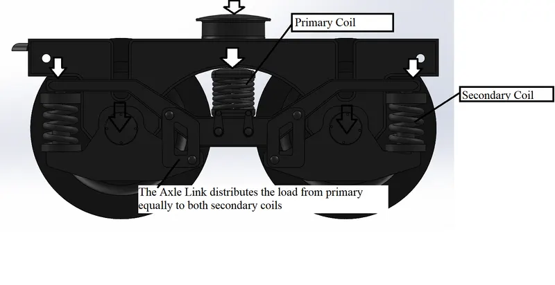
As depicted in the above diagram is the load distribution on the bogie while the locomotive is in the rest position. When the locomotive is in motion i.e., either when it's accelerating or decelerating there was a problem in load distribution where only either of one the wheel sets was under the action of maximum load which is not favorable and may lead to heavy wear on wheels due to uneven loads. To solve this problem we have introduced the Axle Link which is highlighted in the image, the axle link dissipates the load and automatically adjusts at a certain angle because of its cross-link mechanism and distributes the load equally irrespective of motion.
VIEWS OF BOGIE ASSEMBLY:
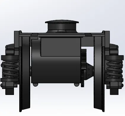
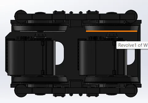
Front_view Bottom_view
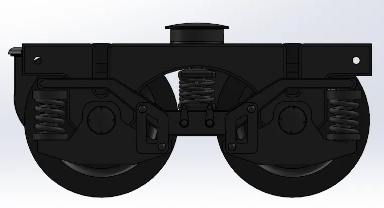
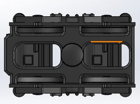
Side_view Top_view
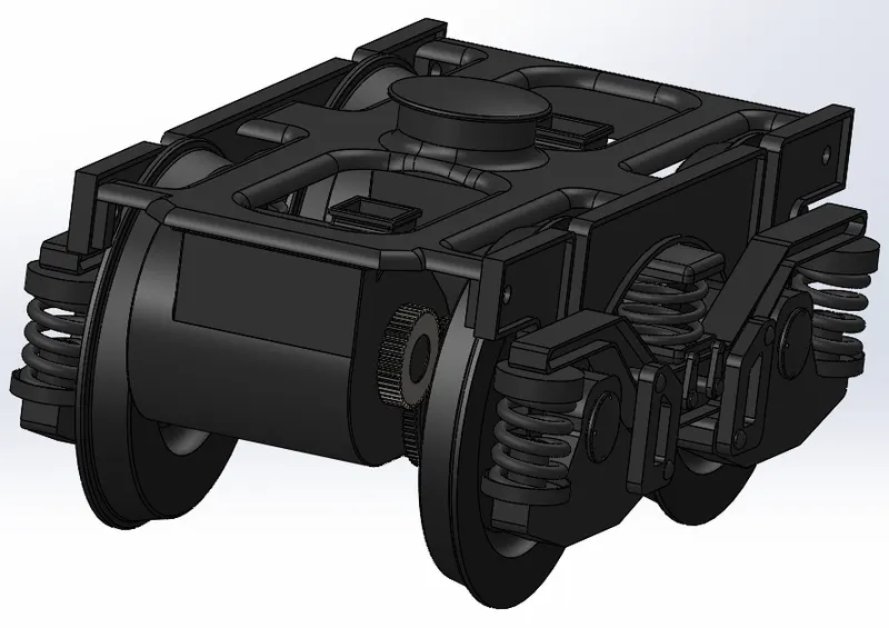
Isometric_view
DESIGN PROCEDURE IN SOLIDWORKS:
- Since we have discussed the principles involved in the bogie now well will see the main core solid modeling features used in designing the bogie system parts.
- If you Isolate and examine each part in the assembly you can see most of the complex shape like a cross-section of the wheel of the axle box unique shapes is done in the sketch feature only.
- This is adapted by me to reduce the tree structure and no of solid features so that the model won't take too much time to compile.
- Most of the parts are generated using extrude command only. The cut extrude is used to make holes and remove material to reduce weight. The fillets and chamfers were added to remove the sharp edges and reduce mesh strain concentration.
- The Bull and the Pinion Gears are designed according to the gear design terminology with the same module of 7 and the rest of the dimensioning is set according to position so that the meshing progresses efficiently.
- Revolve is used for that shaft and wheel and draft command is used to provide the angle cross section on the shaft for the axle box.
- Only different and complex sketches will be for the primary and secondary coil springs where the helix command is used. Dome command is used at the top steering stern.
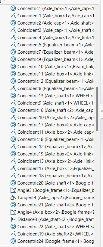
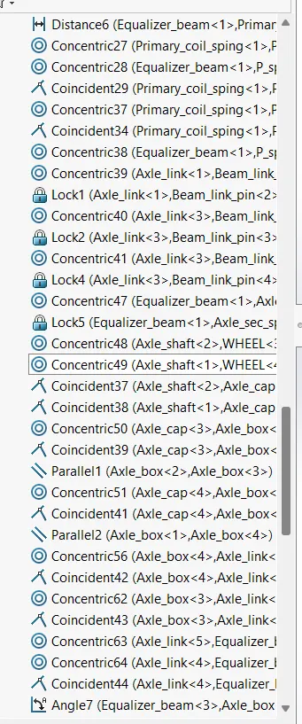
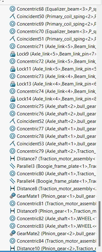
Mates_tree:
Assembly_tree:
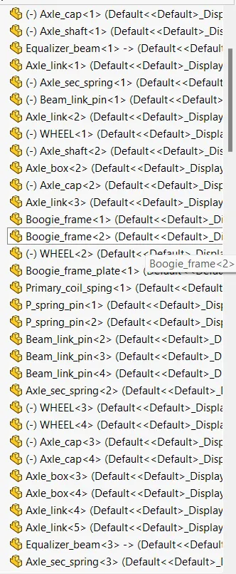
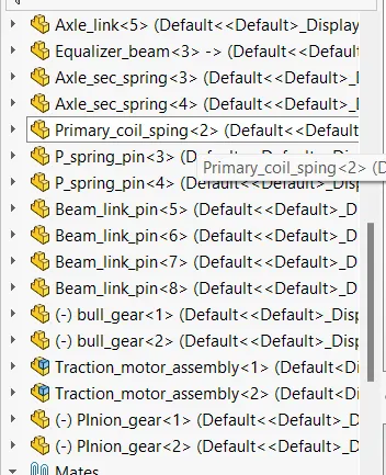
As there are 15 individual parts in only a bogie it's quite complicated to paste their feature tree so please evaluate them from the files uploaded.
2. Traction Motor Assembly:
LIST OF PARTS IN TRACTION MOTOR ASSEMBLY:
- Traction motor
- Motor fixture
- Motor fixture ring.
Design Intent:
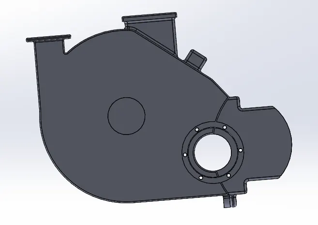
- The traction motor drives the wheelset through the pinion gear and is directly geared to the bull gear. Thus it's fixed to the shaft and frame plate of the bogie thus locking its degrees of freedom.
- The entire motor cannot be assembled in the shaft thus it has to be fixed in parts this is where the motor fixture is bolted with the motor around the shaft as shown in the picture.
- The motor fixture rings are bolted to both the motor fixture and motor to ensure the circularity for the shaft to pass on.
ASSEMBLY VIEWS:
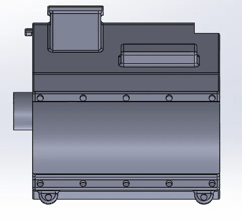
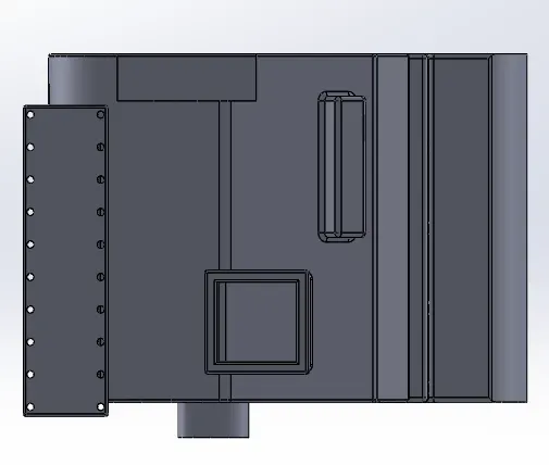
Side_view Front_view Top_view
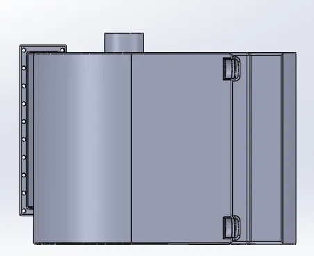
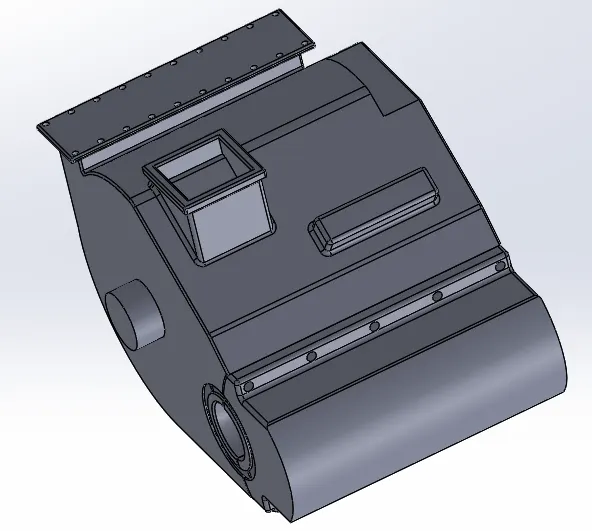
Bottom_view Isometric_view
Assembly_Tree and Featuer trees:
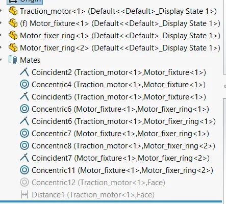
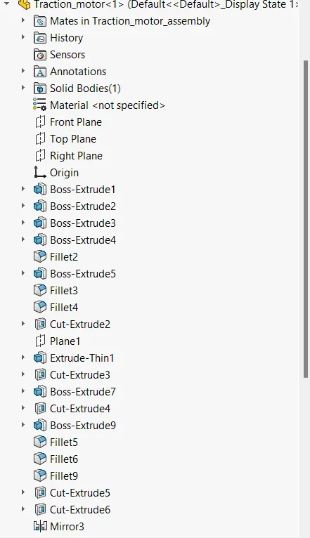
Assembly and Mates Traction_motor_feature_tree
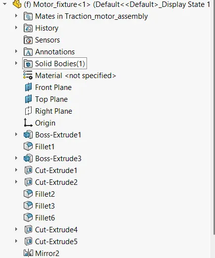
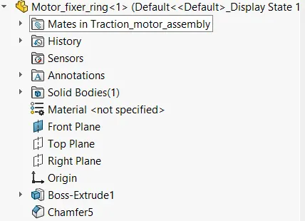
Motor_fixture_tree Motor_fixture_ring
ISOMETRIC_VIEWS OF ALL PARTS:
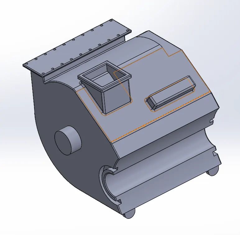
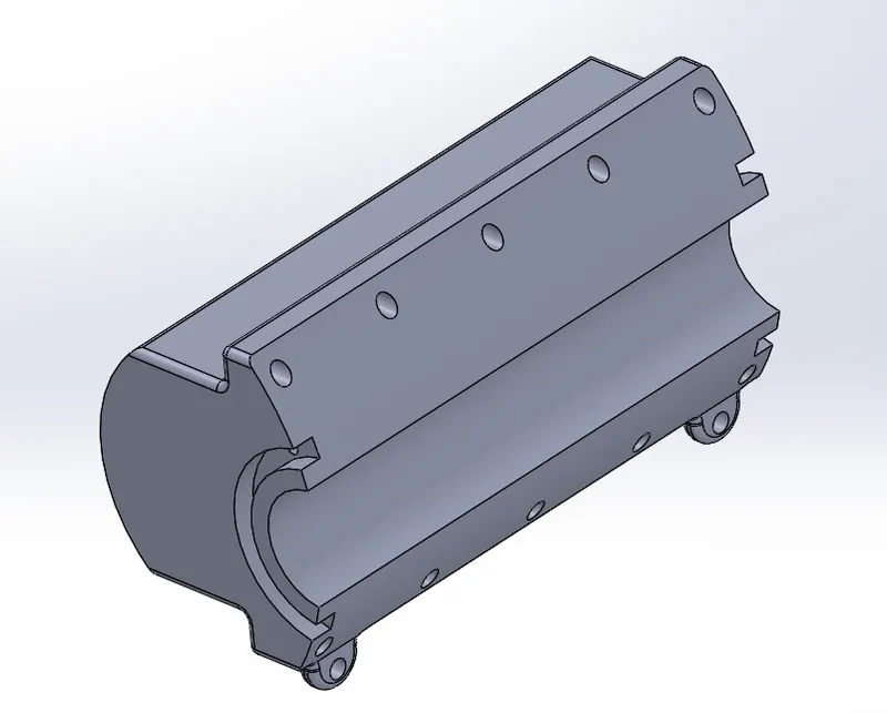
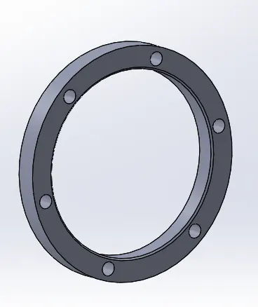
3. Compressor set assembly:
List of parts in Compressor set:
- Compressor set
- Compressor stand
Design Intent:
- The compressor is a necessary essential for braking systems in a locomotive thus not to complicate this much I have used simple design features to design the compressor.
- The extrude feature is used to draw the compressor and the dome is used to give it circulate edging.
- They both are Welded to the compressor stand and the stand is riveted to the frame.
- The extrusions are also given so that the Air rubber pipes will be harnessed to several inputs.
VIEWS and Feature Trees:
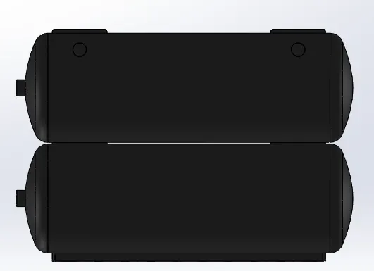
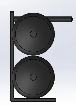
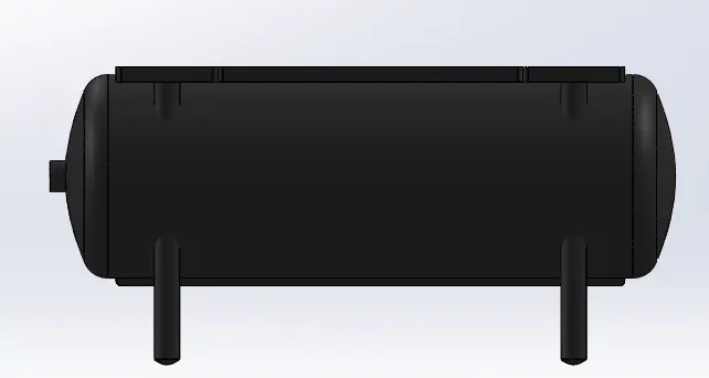
Front_view Side_view Top_view
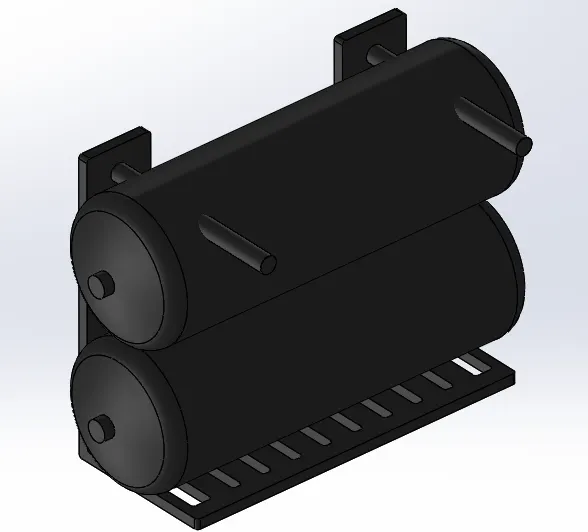
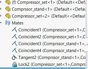
Isometric_view Assembly tree and mates
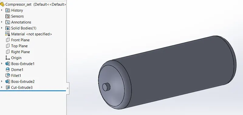
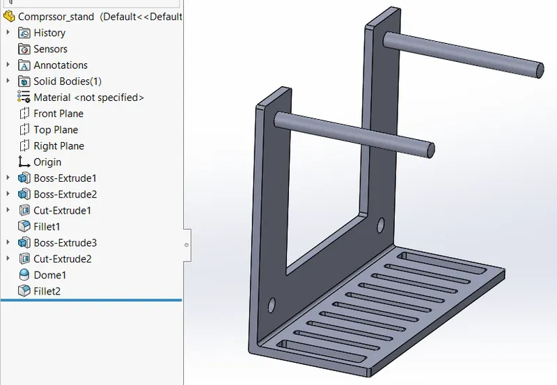
Compressor Feature tree and Isometric view Compressor stand Feature tree and Isometric view
4. Fuel Tank:
- Fuel tank is not much complicated it's a simple feature that is mostly drawn in sketch only
- it's extruded and to fix it the extractions on top are provided so that it is riveted to the frame directly.
- To replicate the rivet feature the dome is provided.
- They are made line copies using the pattern feature.
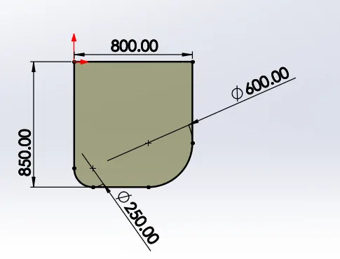
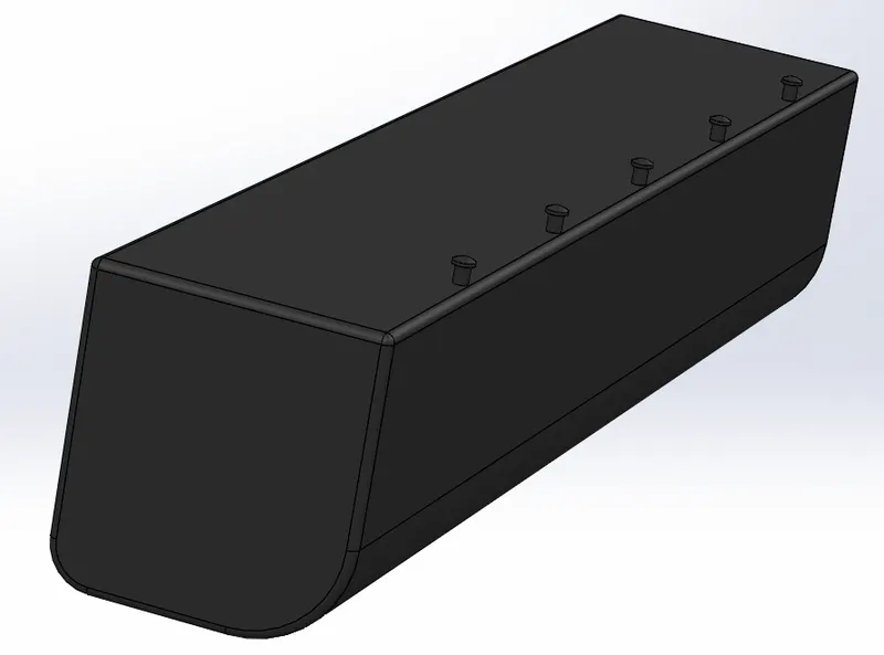
Fuel_tank_profile Fuel_tank_Isometric_view
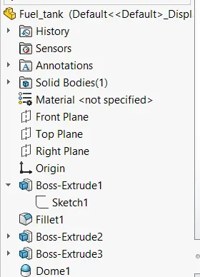
Fuel tank feature Tree
5. Frame:
- The Frame is the most important part because its the intermediate part where the center body and the bogie are assembled.
- Usually reinforced carbon steel material is used to provide good strength.
- Some of the material is removed in between to reduce the weight and sidebar thickness is minimized to reduce the stress concentration
- The circular slot provided where the bogie is assembled to frame and ensure the steering mechanism of the bogie which is explained in the top slide in the bogie selection system.
- The frame is fitted to the center via rivet which is represented in the extrusions which are prolonged using the pattern feature and the dome is given to replicate the riveting feature.
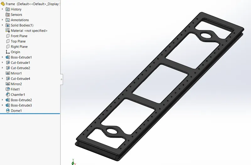
Frame feature tree and Isometric view
6. Centre body:
- The center body is a single body in which I have arranged all upper-faced features of the locomotive.
- The reason for doing this is to give it less computing time when the parts are assembled individually.
- Thus I mostly have replicated every necessary part designed directly by taking the planes with the necessary faces as reference.
- To make the evaluation easy the features are divided into folders of individual core parts that contain their respective features.
- As for the center body's main aim is to show the exterior of the upper section of the locomotive.
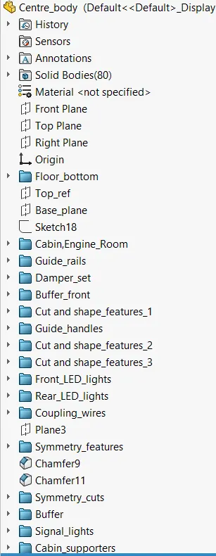
DESIGN INTENT:
- The center is a complex design but is built with simple design features.
- The main compact parts of he Centre body are:
- Upper contre body is mostly built using the extrude and cut extrude features.
- Lower body frame, this part is the core part that sits on the frame and is riveted. The steps, buffer, damper, buffer front, couple, and coupling wires are also attested on the lower frame.
- The slot cut extrudes are given to assemble the turbofan and horn.
- The windows and door slots are done using the cut extrude by taking the faces as the reference.
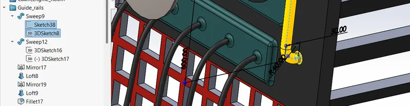
- The railings and the guide rails are designed using the 3D sketch feature and they are drawn in a certain path using the sweep command.
- The main compact parts of he Centre body are:
- The appearance is the most important aspect of the center body.
- Since the center body is the core part for the aesthetic appearance the necessary fillets are provided to give smoothness to the surface.
- For the lights the Dome is provided and the neon light appearance is given to give a good reference.
Guide Rails Profiles:
- The guide rails and similar sweep handles are drawn using the sweep command with a Normal sketch as profile.
- the 3D sketch is used as the path of the rail.
CORE PROFILES OF THE CENTRE BODY:
The Centre body is made of numerous profiles, but we'll see the core profiles that contribute to its shape appearance. These are the main profiles of a center that gives a look as an actual locomotive.
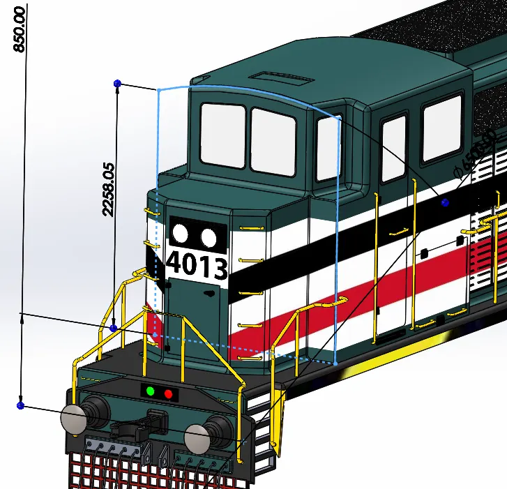
1. Cabin Room Profile:
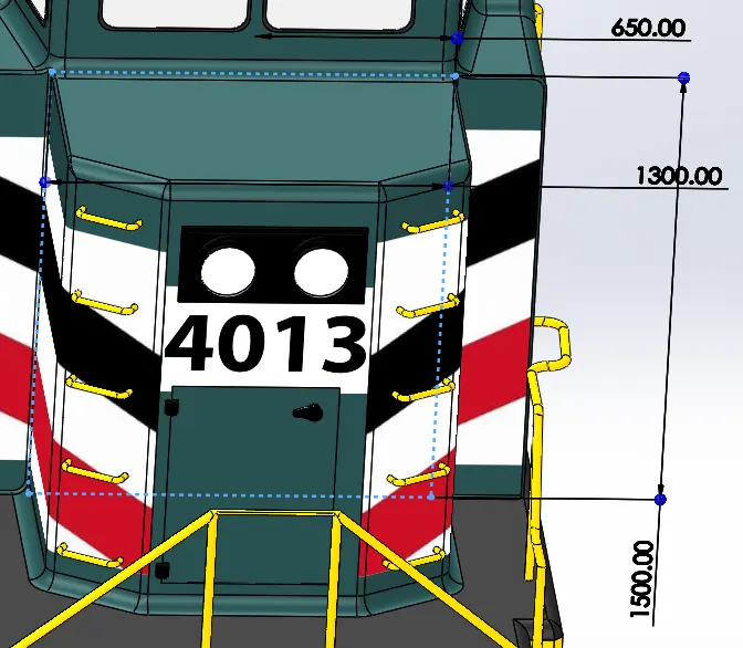
2. Cabin front profile:
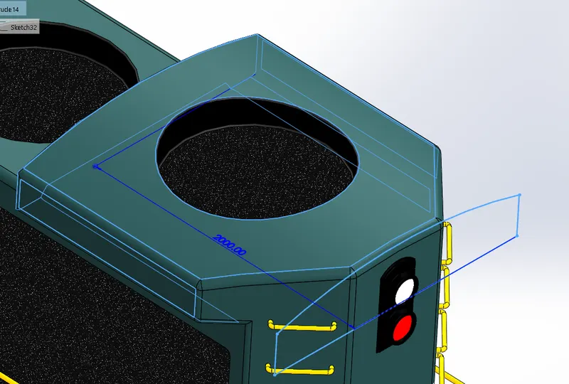
3. Rear Generator Room Top:
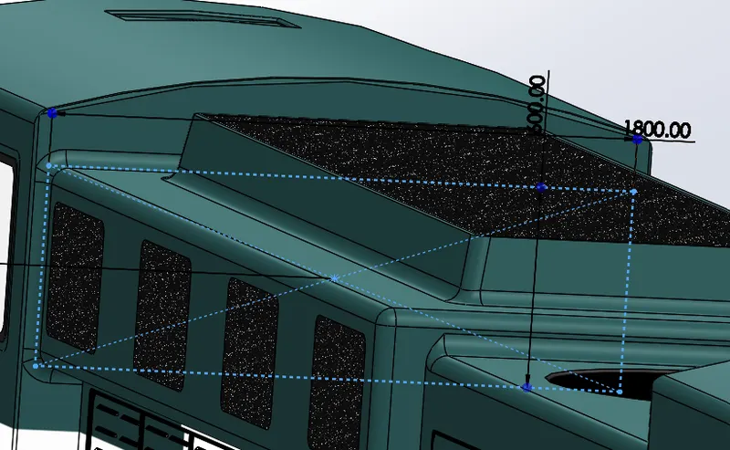
4. Side Cooling Vents:
5. Front Cut Profile:
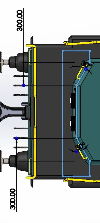
6. Rear Cut Profile:
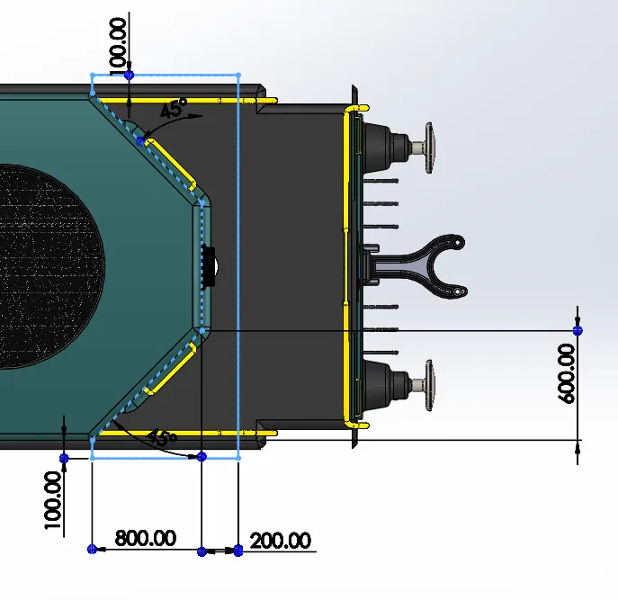
7. Pilot View/Windshield Cut Profile:
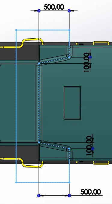
8. Turbofan Cut Profile:
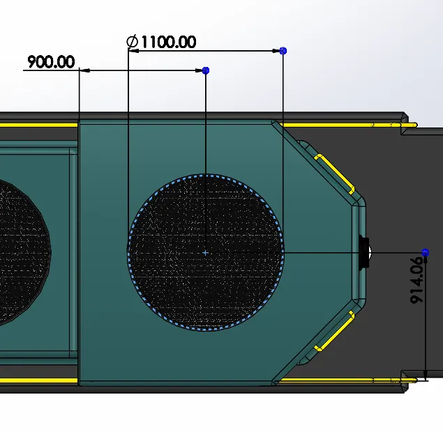
9. Upper cooling exhaust vent:
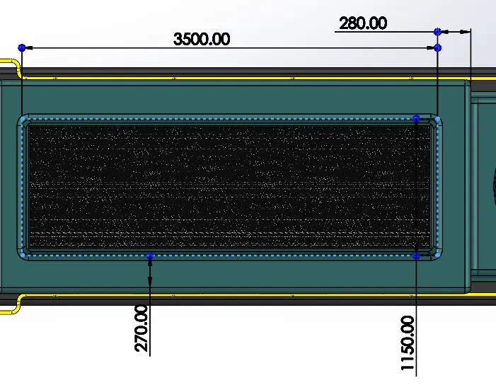
10. Coupling Profile:
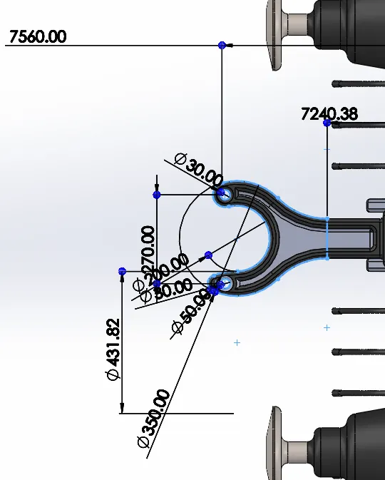
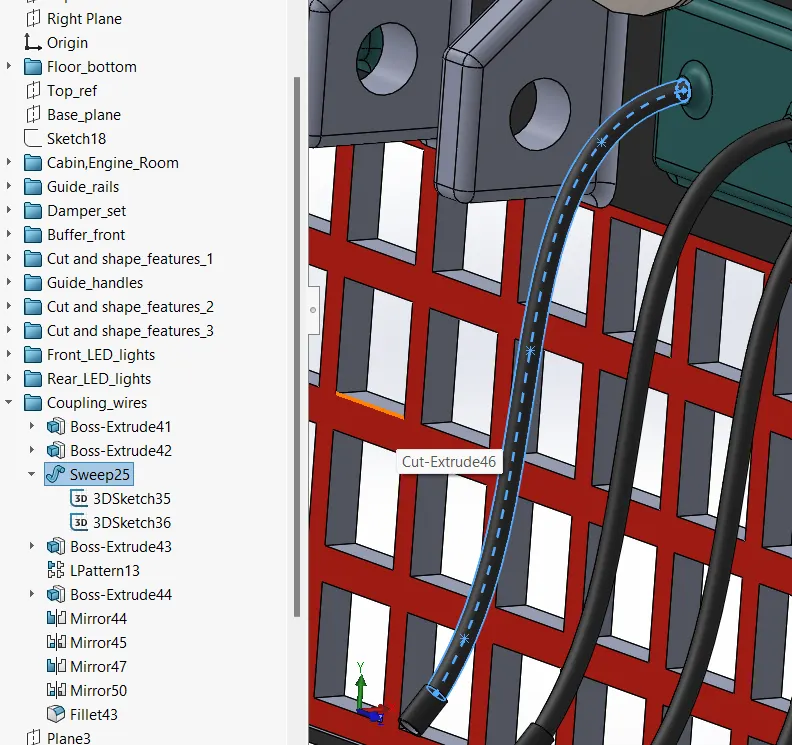
Coupling wire profiles:
- The wire and similar sweep handles are drawn using the sweep command with a Normal sketch as the profile.
- the 3D sketch is used as the path of the harness.
Decoration Features:
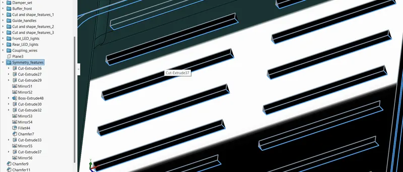
- The side opening of the locomotive is provided to open and close the door for servicing.
- Thus to give the sides doors the replica I had to each stape and chamfer the strap to give it the look like it is an air opening.
- The lines of straps are 10mm in length and 50 nos in line from top to bottom.
- This feature is complicated and took a lot of computing time to perform the chamfer and the gaps using the cut extrude command.
Explaining the appearance:
- The painted color is added to the main faces of the center body.
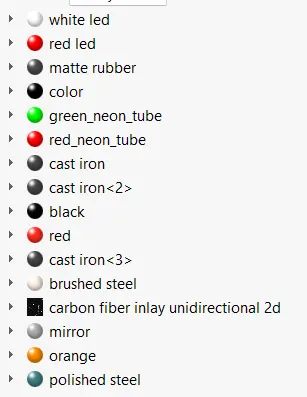
- The white led is used for headlights and signal lights.
- red and green neon lights for signal lights.
- Matte rubber is for coupling wire at the front.
- Black paint is used for the floor.
- Cast iron is used on the base and side floors.
- Mirror appearance used glass mirrors.
- Orange is used for the railings and polished steel for the buffer.
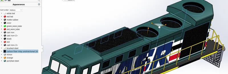
The carbon fiber appearance is used to replicate the cooling vents and smoke exhausts in black color as shown in the below image.
Decals:
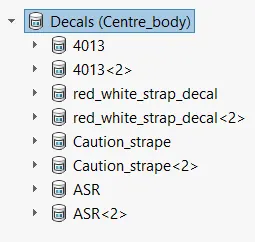
- The decals are the most important attributes that contribute to the aesthetics of the center body.
- As shown in the ASR, 4013, caution Strape in yellow and black, white and black straps on the surface are downloaded on the internet.
- The decal placement is done manually no additional features are created for the decals.
VIEWS:
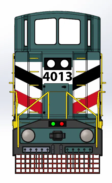
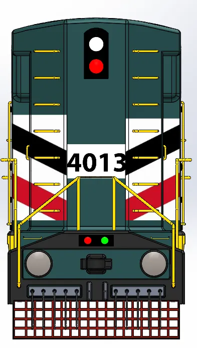
Front_view Back_view
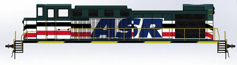
Side_view

Top_view

Bottom_view
7. Horn:
- The is designed using the revolve option.
- The inside of the horn is shelled to give it a good interior look.
- Horn is placed is the top of the cabin of the center body and is given a simple appearance.
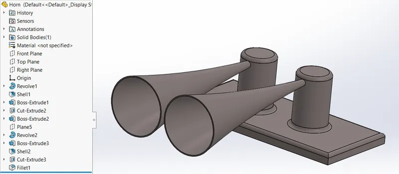
Feature_tree and Isomteic View
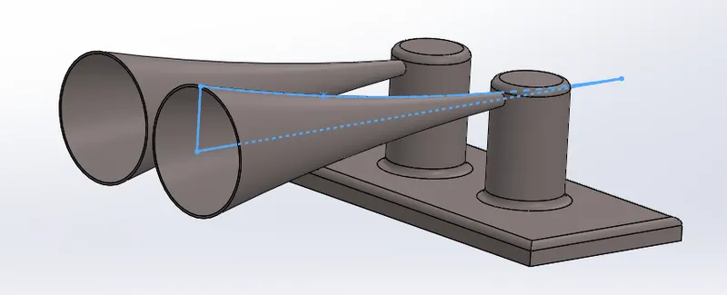
Horn_revolve Profile
8. Turbofan:
- Turbofan is a little bit complicated part where the wing is designed using two profiles as shown below.
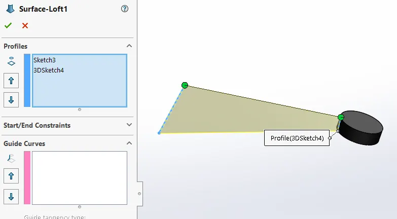
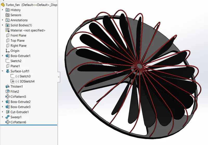
- Using the surface loft profile is generated and thickened.
- The sharp edges are filleted and pattern command is used to make copies around.
- The bars are created using sweep and patterned.
9. Sandbox:
- Sandbox is placed in the front before the buffer.
- It's usually not visible but the purpose of the sandbox is that, during deceleration to increase the traction, sand is poured out during braking.
- Sandbox is a simple design and the profile is as below.

Assembly:
- Finally all the parts are assembled and appearance is added to each part.
Views:
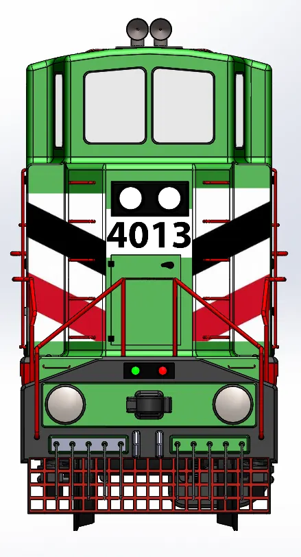
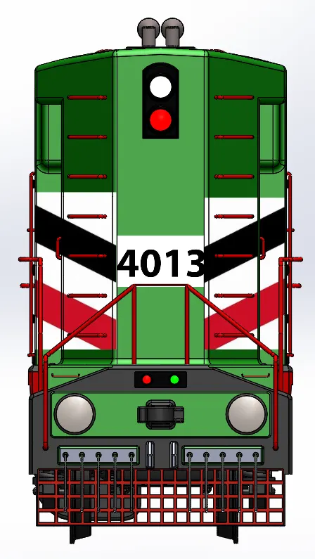
Front_view Back_view
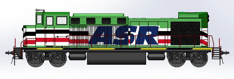
Side_view

Top_view

Bottom_view
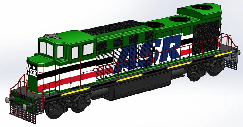
Isometric_view 1
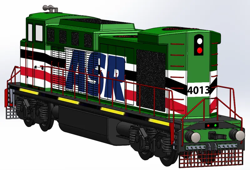
Isometric_view 2
RENDERS:
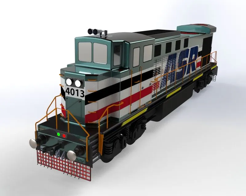
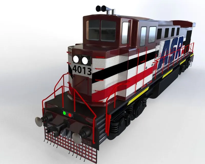

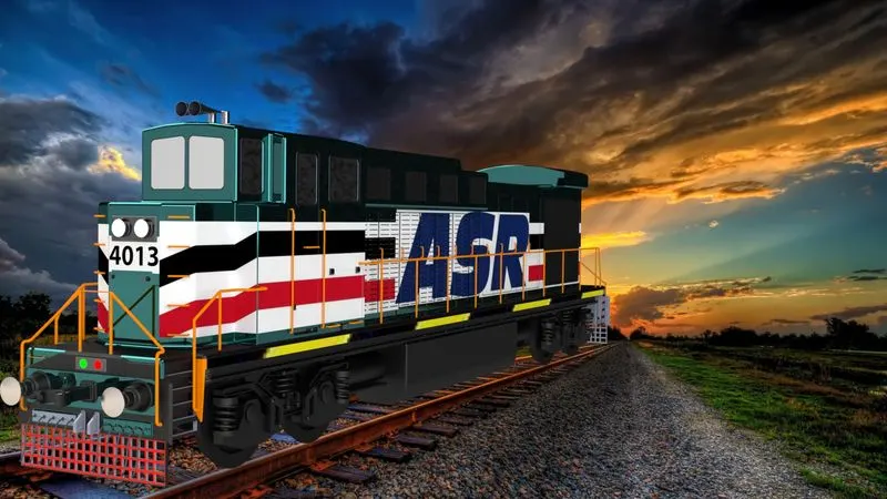
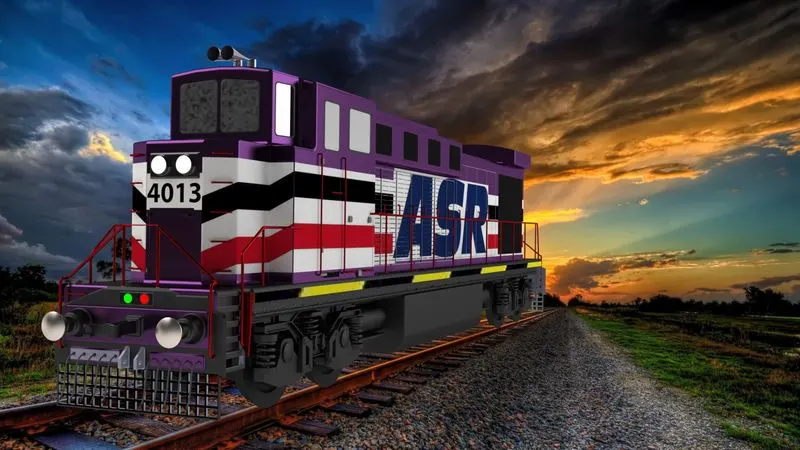
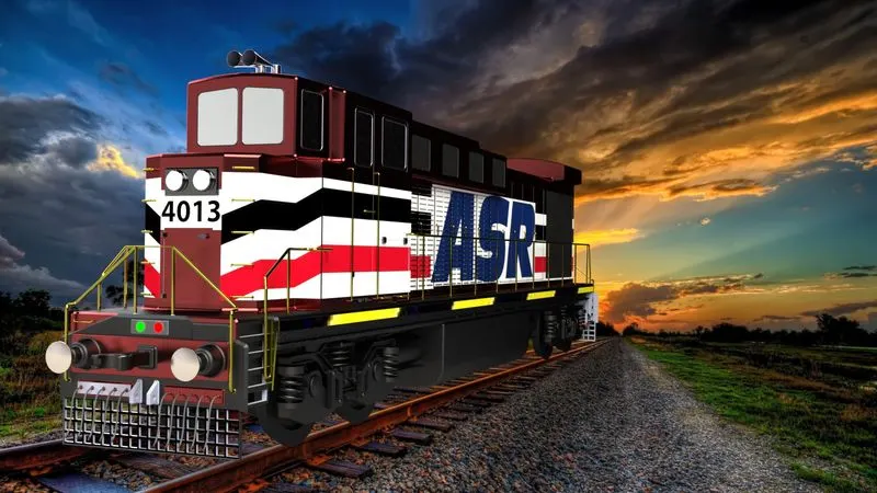
Conclusion:
The Final independent project of Conceptual modeling of the full-scale ASR locomotive has been created, the necessary sub-assemblies have been created and mates have been added. The rendering is done in SOLIDWORKS Visualize.