FINAL INDEPENDENT PROJECT
Assembly and rendering of a yacht
Objective: To assemble a yacht and render it with proper views and environments.
Introduction: For studying different tools and features of the SOLIDWORKS, this project was selected. During the design of each parts, efforts were made to use each and every tool in SOLIDWORKS and to get familiarized in it. This project also aims in familiarization of SOLIDWORK for rendering and editing.
Design Methodology:
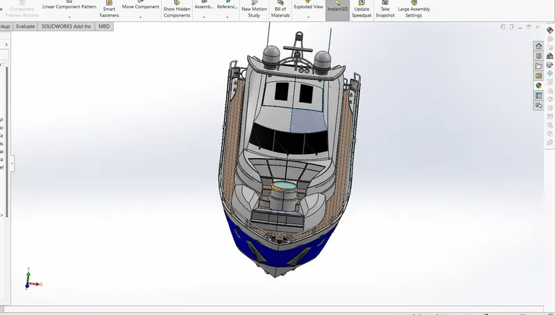
As shown in the flow chart at first, I started by designing individual parts of the yacht in SOLID WORKS. After designing the part models, I switched to assembly model and assembled every part with sufficient relations. As assembly was completed it was rendered with different backplates and environments.
Description:
For the assembly of Yacht at first all the parts should be designed the parts are:
1.Propeller:
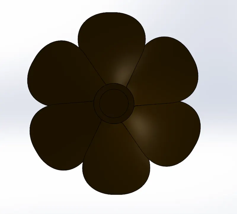
Features used in the part design are:
- Revolve: Used to create the revolve base in the centre.
- Loft: Used to create a single leaf of the propeller.
- Cut Extrude: Used to remove from base.
- Circular Pattern: Used to pattern the leaf.
- Fillet: To remove sharp edges.
2.Radar
Features used in the part design are:
- Boss-Extrude: Used to create a 3-D base from a 2-D sketch.
- Cut-Extrude: To remove material from a base.
- Sketch Pattern: Used to pattern 2-D sketch.
- Mirror: To Pattern a body along a plane.
- Split Line: Used here as a reference for text.
3.Hull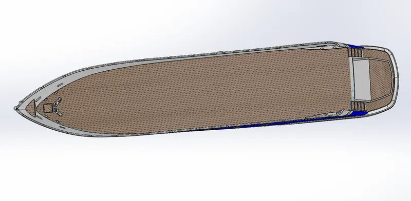
Features used in the part design are:
- Surface Loft: To create surfaces between edges or lines, minimum condition for applying this is two edge curves and a guide curve.
- Projective Curve: To project two different curves in different planes.
- Surface Extrude: To create a surface from a 2D sketch.
- Surface Trim: To remove excess surface from surface extrudes.
- Surface Fill: To fill gaps in Between surface extrudes.
- Surface knit: To merge and control gap between to surfaces.
- Shell: To make a hollow feature in solid bodies. Here the removed body is saved for garage door.
- Reference Plane: A feature used to create new planes for sketching.
- Sweep: To create required profile throughout a path.
- Fillet: To avoid sharp edges and to provide finishing.
- Chamfer: To creates a bevelled feature on selected edges, faces, or a vertex.
- Revolve: To create boss/base around an axis.
- Dome: To create dome feature in the surfaces, for providing more finishing.
- Helix/Spiral: For creating spring in the part.
- Linear Pattern: Used to pattern bodies in a linear path.
- Delete Face: To delete faces not required here delete with patch option is used for more surface finish
- Mirror: To Pattern a body along a plane.
- Garage Door
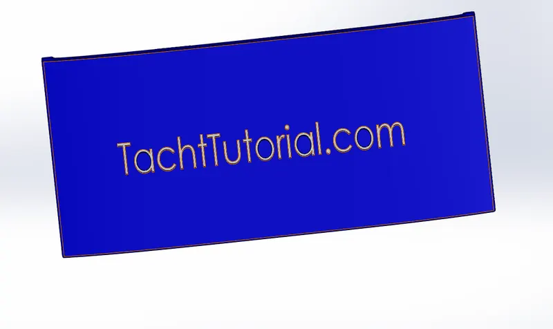
Features used in the part design are:
- Cut Extrude: To remove material from a base.
- Fillet: To avoid sharp edges and to provide finishing.
- Reference Plane: A feature used to create new planes for sketching.
- Mirror: To Pattern a body along a plane.
5.Front Seat
Features used in the part design are:
- Surface sweep: To create a surface profile along a path.
- Surface Extrude: To create a surface from a 2D sketch.
- Surface Trim: To remove excess surface from surface extrudes.
- Surface Loft: To create surfaces between edges or lines, minimum condition for applying this is two edge curves and a guide curve.
- Surface Fill: To create surfaces enclosing 3d sketches or edges.
- Surface knit: To merge and control gap between to surfaces.
- Shell: To make a hollow feature in solid bodies. Here the removed body is saved for garage door.
- Reference Plane: A feature used to create new planes for sketching.
- Chamfer: To creates a bevelled feature on selected edges, faces, or a vertex.
- Revolve: To create boss/base around an axis.
- Dome: To create dome feature in the surfaces, for providing more finishing.
- Fillet: To avoid sharp edges and to provide finishing.
6.Middle Seat
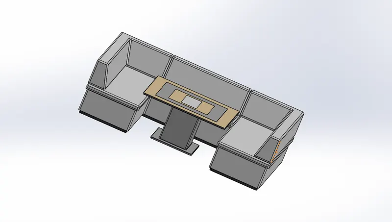
Features used in the part design are:
- Boss-Extrude: Used to create a 3-D base from a 2-D sketch.
- Mirror: To Pattern a body along a plane.
- Fillet: To avoid sharp edges and to provide finishing.
- Chamfer: To creates a bevelled feature on selected edges, faces, or a vertex.
- Cut-Extrude: To remove material from a base.
7.Rear Seat
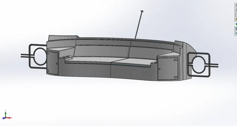
Features used in the part design are:
- Surface sweep: To create a surface profile along a path.
- Surface offset: To offset a surface to a certain distance.
- Surface Trim: To remove excess surface from surface extrudes.
- Ruled surface: To create surfaces that extend out in a specified direction from selected edges.
- Surface Trim: To remove excess surface from surface extrudes.
- Surface Loft: To create surfaces between edges or lines, minimum condition for applying this is two edge curves and a guide curve.
- Reference Plane: A feature used to create new planes for sketching.
- Sweep: To create required profile throughout a path.
- Fillet: To avoid sharp edges and to provide finishing.
- Mirror: To Pattern a body along a plane.
- Revolve: To create boss/base around an axis.
8.Superstructure
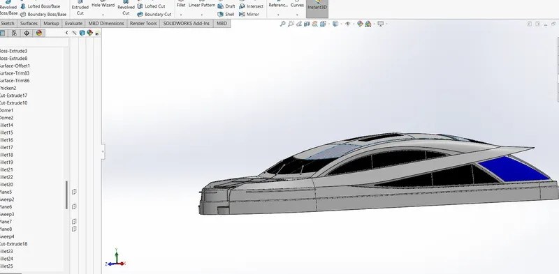
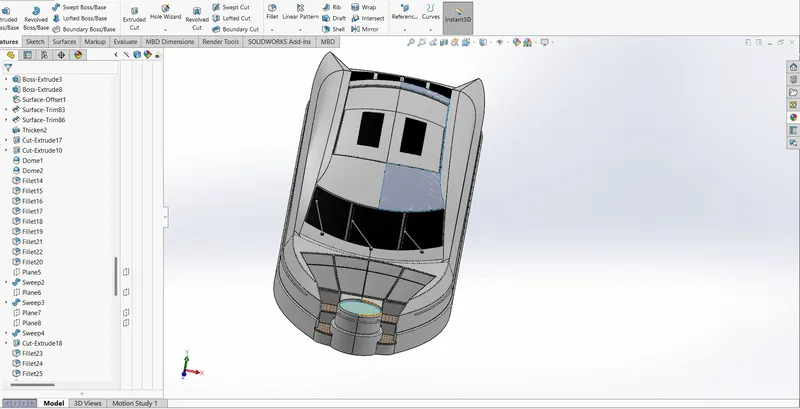
Features used in the part design are:
- Surface Extrude: To create a surface from a 2D sketch.
- Surface Trim: To remove excess surface from surface extrudes.
- Surface Loft: To create surfaces between edges or lines, minimum condition for applying this is two edge curves and a guide curve.
- Surface Fill: To create surfaces enclosing 3d sketches or edges.
- Surface knit: To merge and control gap between to surfaces.
- Reference Plane: A feature used to create new planes for sketching.
- Chamfer: To creates a bevelled feature on selected edges, faces, or a vertex.
- Surface offset: To offset a surface to a certain distance.
- Ruled surface: To create surfaces that extend out in a specified direction from selected edges.
- Surface sweep: To create a surface profile along a path.
- Mirror: To Pattern a body along a plane.
- Boss-Extrude: Used to create a 3-D base from a 2-D sketch.
- Cut-Extrude: To remove material from a base.
9.Radar Mast
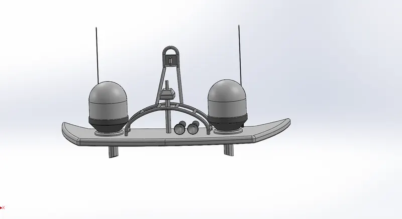
Features used in the part design are:
- Boss-Extrude: Used to create a 3-D base from a 2-D sketch.
- Reference Plane: A feature used to create new planes for sketching.
- Sweep: To create required profile throughout a path.
- Fillet: To avoid sharp edges and to provide finishing.
- Mirror: To Pattern a body along a plane.
- Revolve: To create boss/base around an axis.
- Shell: To make a hollow feature in solid bodies.
- Combine: Used to merge bodies.
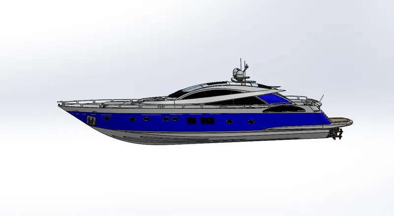
Different views of assembled yacht are given below: