FINAL INDEPENDENT PROJECT
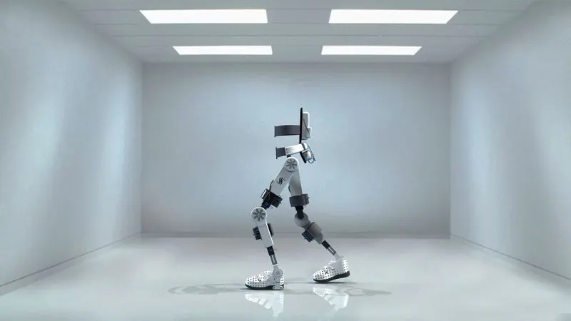
TITLE: -DESIGN OF WALKING ASSIST DEVICE USING SOLIDWORKS
OBJECTIVE:
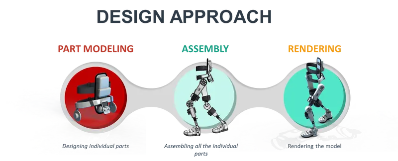
- To design individual parts of the Walking assist device
- To assemble all the individual parts of the Walking assist device
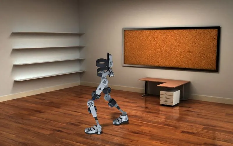
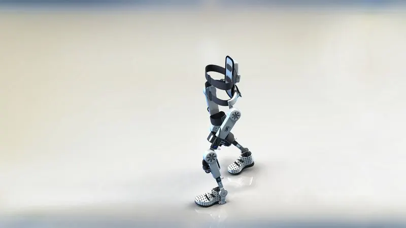
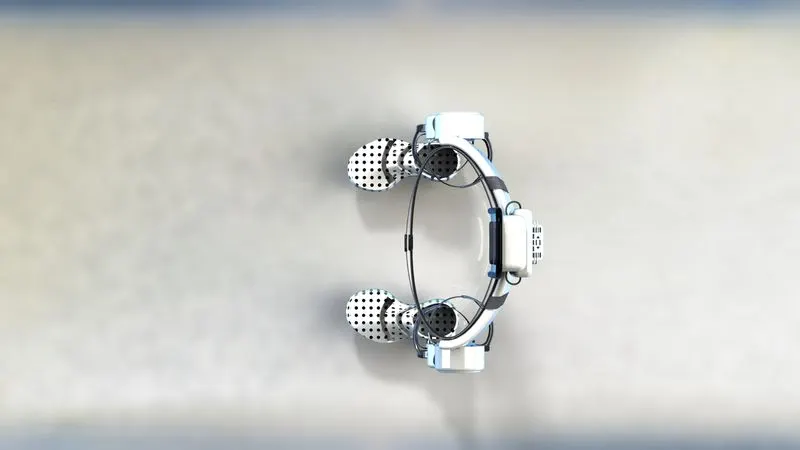
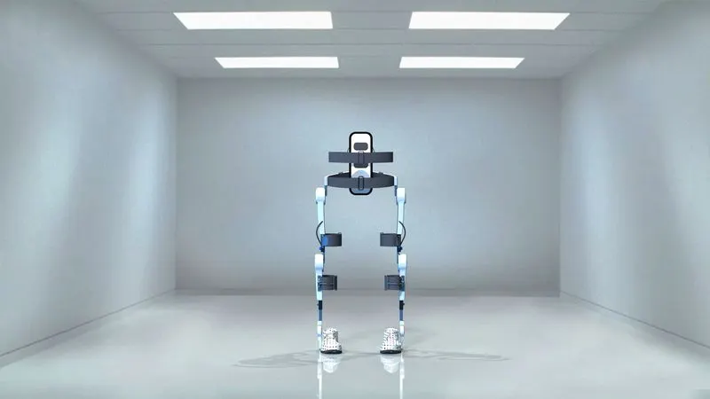
- To render the model by adding appearances, decals, lights, cameras, and background scene
INTRODUCTION:
The walking assist device is a wearable robotic exoskeleton that provides powered hip and knee motion to enable individuals with spinal cord injury (SCI) to stand upright, walk, turn, and climb and descend stairs. It detects movement of the hip joint during walking with sensors built into the right and left motors, and guides the movement.
SOFTWARE USED:
- SOLIDWORKS 2017
- PHOTOVIEW 360
PART MODELLING
FEATURES USED WHILE MODELLING:
- SKETCH: Sketch is a 2D representation of the model. Some of the sketch commands are
- Line- In sketch line is created by choosing different types like centerline, midpoint line, and construction line
- Arc- It is a three-pointed arc that can be created on basis of positioning points.
- Smart Dimensions- The dimensions of any sketches can be changed easily in required situations by using this command.
- Sketch picture - This command is useful in inserting required pictures for the modeling part.
- Offset- It Offsets one or more sketch entities or selected model edges
- Mirror- It used to create a duplicate curve about the required curve or plane
- Spline- It is used to create irregular curves
- Trim – it is used to trimming curves.
- Extend - It can extend the entities to nearby geometry
- EXTRUDE BOSS/BASE- It is used to create 3d objects from reference sketches.
- REVOLVE BOSS/BASE- It is used to create a solid feature by revolving a sketch about an axis
- SWEEP- It is a tool in which a 2D cross-section is moved along a pre-set path to creating a 3D object.
- LOFT- Loft is almost the same as sweep, but it requires more than 1 cross-section
- PROJECT CURVE- It is a tool used to form 3D curves from two 2D curves from two different planes
- EXTRUDE CUT- it is used to remove material from a 3d object by using a reference sketch.
- REVOLVE CUT- It is used to cut a solid feature by revolving a sketch about an axis.
- FILLET- It creates a rounded internal or external face on the part
- CHAMFER- It creates a straight line which bevels the edges of objects
- LINEAR PATTERN- It is used to create multiple instances of one or more features along one or two linear paths
- CIRCULAR PATTERN- It is used to create multiple instances of one or more features about an axis
- SWEEP SURFACE- It is a tool in which a 2D cross-section is moved along a pre-set path to creating a surface
- KNIT SURFACE- The Knit Surface tool is used to combine two or more surface
- TRIM SURFACE- It is used to trim surfaces by using curves, sketches, or surface as a trim tool
- FILLED SURFACE- Constructs a surface patch within a boundary defined by existing model edges, sketches, or curves.
- 3D SKETCH- Creates a new sketch in 3D space.
- Ruled Surface- Inserts ruled surfaces from edges.
- THICKEN- Creates a solid feature by thickening one or more adjacent surfaces which are already knit.
- Delete Face- Deletes faces from solid bodies to create surfaces or deletes faces from surface bodies.
- Extend Surface- Extends the edge, multiple edges, or the face on a surface, based on end conditions and extension type.
COMPONENTS:-
BODY FRAME
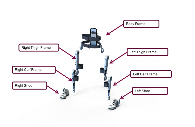
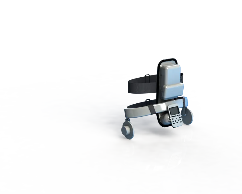
The device's main control unit incorporates the control computer, battery, and motors positioned on both sides that connect the thigh frames.
Features used:
- Sketch
- Projected Curve
- Lofted Surface
- Trim Surface
- Extruded Surface
- Knit Surface
- Extruded Boss/Base
- Extruded Cut
- Fillet
- Chamfer
- Swept Boss/Base
- Revolved Boss/Base
- Helix and Spiral
- Linear Pattern
- 3D Sketch
- Mirror
- Split Line
- Appearance
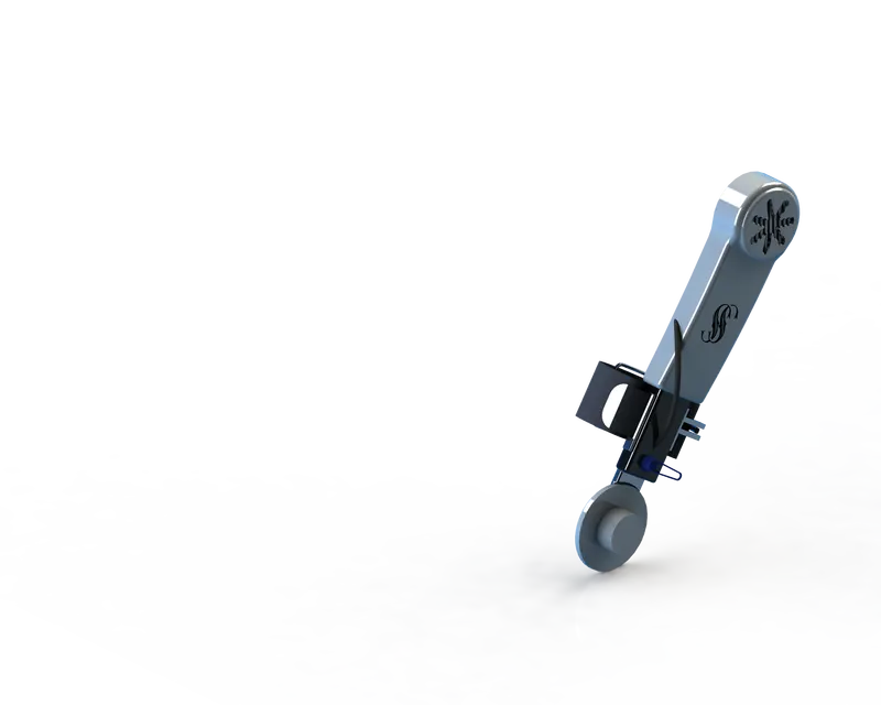
THIGH FRAME
It guides the beginning and kicking movement of the lower legs by assisting bending and extension of the hip joints with the computer-controlled motors.
Features used:
- Sketch
- Projected Curve
- Lofted Surface
- Trim Surface
- Extruded Surface
- Knit Surface
- Extruded Boss/Base
- Extruded Cut
- Fillet
- Chamfer
- Swept Boss/Base
- Revolved Boss/Base
- Helix and Spiral
- Linear Pattern
- 3D Sketch
- Split Line
- Thicken
- Appearance
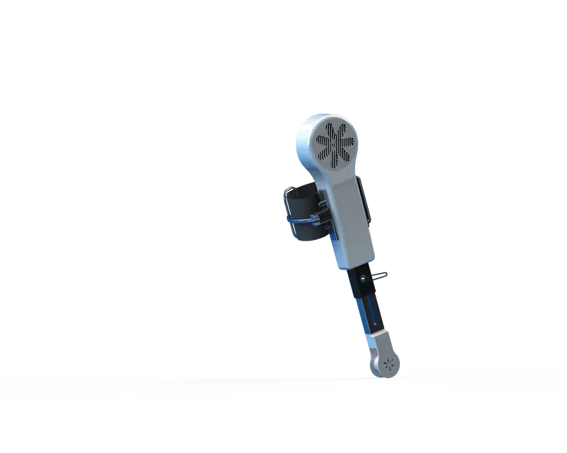
CALF FRAME
It is used to transfer motion to the shoe by using the ankle motor. It consists of leather straps that support the calf.
Features used:
- Sketch
- Projected Curve
- Lofted Surface
- Trim Surface
- Extruded Surface
- Knit Surface
- Extruded Boss/Base
- Extruded Cut
- Fillet
- Chamfer
- Swept Boss/Base
- Revolved Boss/Base
- Linear Pattern
- 3D Sketch
- Split Line
- Thicken
- Appearance
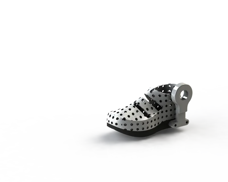
SHOE
It is used to support the foot. It allows the movement of the ankle joint.
Features used:
- Sketch
- Projected Curve
- Trim Surface
- Extruded Surface
- Knit Surface
- Extruded Boss/Base
- Extruded Cut
- Fillet
- Chamfer
- Swept Boss/Base
- 3D Sketch
- Thicken
- Appearance
ASSEMBLY
COMMANDS USED:
- Insert component
- Mates
MATES USED:
- Coincident
- Concentric
- Limit angle
RENDERING
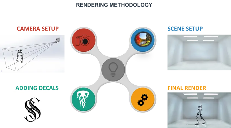
FINAL RENDER IMAGES
CONCLUSION
By doing this project I enhanced my knowledge of solid modeling, assembly, and rendering of a model using Solidworks and photoview 360.
- Yogesh KhairnarGreat job and design, the rendering done is awesome !