Fender Design - Wheel Arch Challenge
FENDER DESIGN ANALYSIS FOR WHEEL ARCH AREA
Objective:
To calculate the fender wheel arch area for the given front fender design and to analyse its standards to prove whether the fender design will pass the European standards or not.
Description:
Fender:
Fender is the American English term for the part of an automobile, motorcycle or other vehicle body that frames a wheel well (the fender underside).
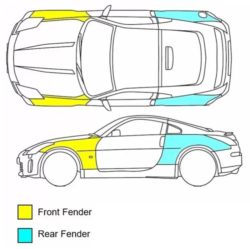
Its primary purpose is to prevent sand, mud, rocks, liquids, and other road spray from being thrown into the air by the rotating tire.
When vehicle is moving, tires pick up stones and others and hurl them in all directions. Fenders are basically present to prevent any injuries to pedestrians and contain the motion of these particles.
There are two types of fenders used in cars. They are,
- Full bumper type and
- Half bumper type.
- Full bumper type:
In full bumper type, the fender covers the entire wheel area from the front to the body side. This type is widely used by the OEMs and automotive industries in early days.
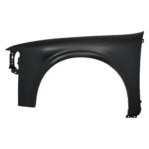
Full bumper type front fender.
- Half bumper type:
In half bumper type, the fender only covers the one-third area of the wheel from the bodyside to front. This is because to reduce the production cost and material wastage compared to the full bumper type. This type is widely used by the OEMs and automotive industries now-a-days.
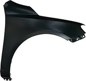
Half bumper type front fender.
Fender wheel arch:
The area which is above the wheel and the edge connecting the fender and its underside is said to be the fender wheel arch area.
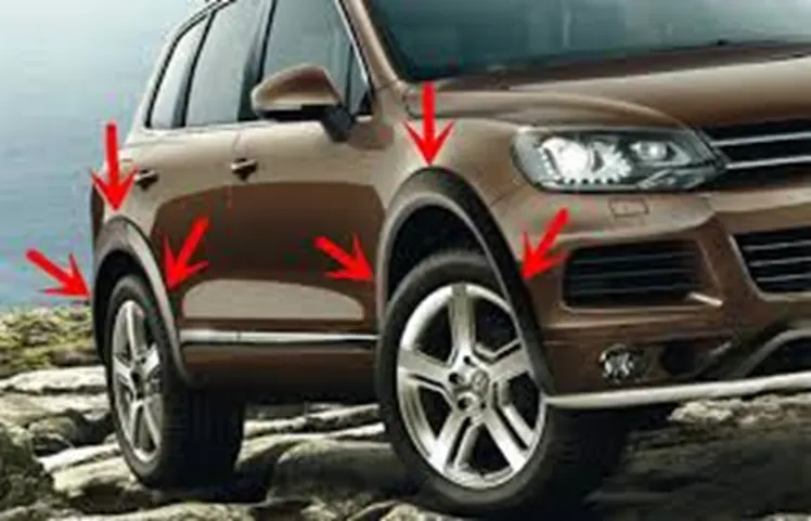
The arrow marks shows the fender wheel arch.
Sticky materials, such as mud, may adhere to the smooth outer tire surface, while smooth loose objects, such as stones, can become temporarily embedded in the tread groves as the tire rolls over the ground. These materials can be ejected from the surface of the tire at high velocity as the tire imparts kinetic energy to the attached objects. For a vehicle moving forward, the top of the tire is rotating upward and forward, and can throw objects into the air at other vehicles or pedestrians in front of the vehicle. To avoid this, some standards are followed by the OEMs, where the vehicle going to be operated (like country or region) for pedestrians safety.
These standards are structured by the observational results according to the road condition, traffic, average speed of the vehicle etc…
The fender wheel arch area is calculated according to the wheel clearance, suspension clearance and turning radius clearance of the vehicle while in rest and moving conditions.
There are three regulation standards for fender wheel arch design. They are,
- Japan regulation standard
- European regulation standard and
- U.S regulation standard.
1.Japan regulation standard:
The clearance between the wheel and fender wheel arch must be greater than 5mm in all the three positions (A, B & C which is shown in the following picture).
Wheel guard requirement: the value of ‘a’ shall be more than 5mm at a line 30º forward and 50º rearward from the central vertical axis of wheel.
To validate, measure the clearance L of tire, hub, cap & fender in three different positions within area K and produce the clearance check chart according to the requirements of Japanese regulation standard.
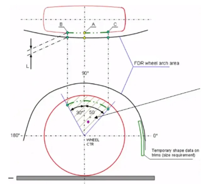
Sections considered in Japan regulation standard is shown.
2.European regulation standard:
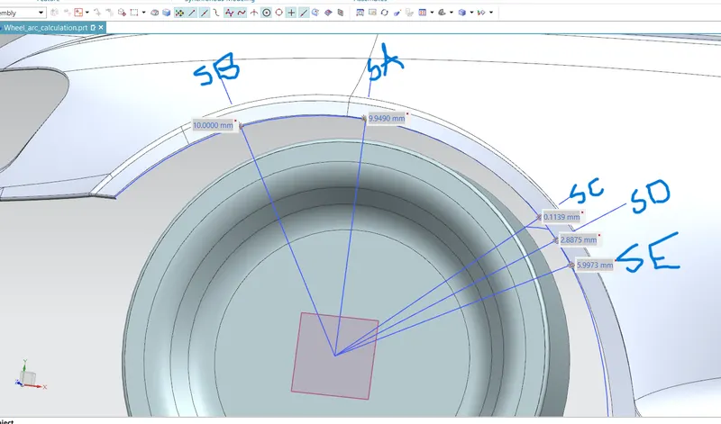
The clearance between the wheel and fender wheel arch must be greater than 10mm in sections SA-SA, SB-SB, SC-SC, SD-SD and SE-SE to satisfy the European regulations.
Wheel guard requirement: the value of ‘a’ shall be more than 5mm at a line 30º forward and 50º rearward from the central vertical axis of wheel.
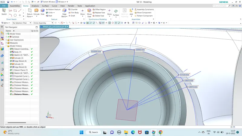
To validate, measure the clearance L at sections SA-SA, SB-SB, SC-SC, SD-SD and SE-SE (which is shown in the following picture) and produce the clearance check chart according to the requirements of European regulation standard.
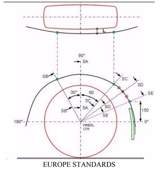
Sections considered in European regulation standard is shown.
3.U.S regulation standard:
The clearance between the wheel and fender wheel arch must be greater than 5mm in all positions.
The value of ‘a’ shall be more than 5mm at a line 30º forward and 50º rearward from the central vertical axis of wheel.
To validate, measure the clearance at every 10º from -20º to 180º and produce the clearance check chart according to requirements of U.S regulation standards.
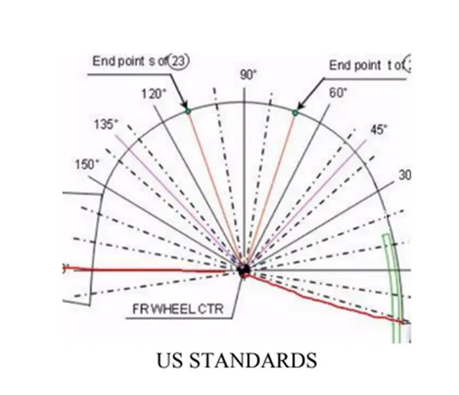
Sections considered in U.S regulation standard is shown.
FENDER DESIGN FOR EUROPEAN REGULATION STANDARD IN NX CAD :
This is the class A surface design of WHEEL ARC :
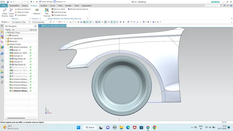
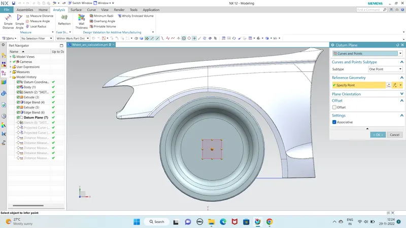
After next we take a DATUM PLANE and select a curves and points, select a curve of wheel and place the datum plane.
SKETCH IN WHEEL ARC :
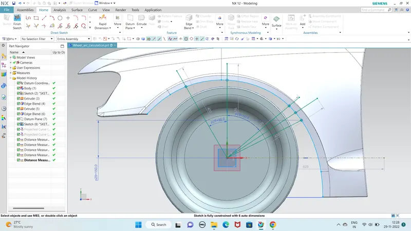
Firstly i had taken the line along the horizontal as a reference line after and according to the european regulations i draw the line with providing same angles. From the derived lines command i had taken the mid point line. Then i convert the fender arc to 2d curve and specify the points with selecting line and curve.
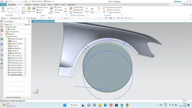
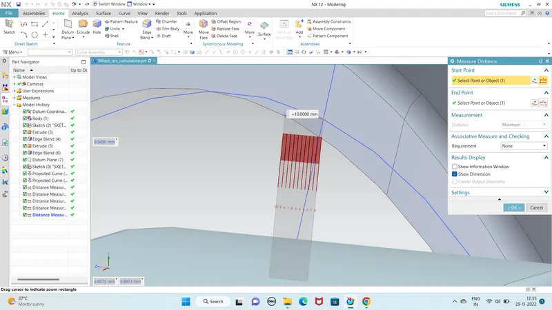
Take a project curve in th curve command specify the points by selecting fender and placing vector on to the Z axis.
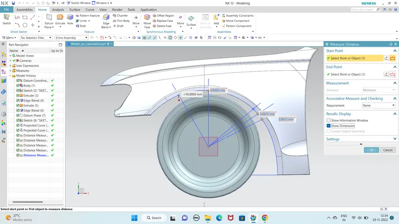
By measuring the distance of two point then we get the idea about it pass or fail.
Clearance observation table:
|
Sections |
European regulation standard clearance value (in mm) |
Clearance value obtained from the given fender design (in mm) |
Result |
|
SA |
10 |
9.949 |
FAIL |
|
SB |
10 |
10.000 |
PASS |
|
SC |
10 |
-0.113 |
FAIL |
|
SD |
10 |
-2.884 |
FAIL |
|
SE |
10 |
-5.997 |
FAIL |
The given fender design is failed in wheel arch analysis, according to the European regulation standard. The clearance at section SB only passed in this analysis. So, this is informed to the styling team to correct this design until it gets cleared in the fender wheel arch analysis to proceed further.
Conclusion:
The fender wheel arch area is calculated and the given fender design is failed in the wheel arch analysis according to the European regulation standard.