Fender Design - Wheel Arch Challenge
Introduction:
Every car industry is under constant development because of the competition between different brands but mostly because of the constant rising demands from customers. A new car always has to present the state of the art in every aspect.This also includes a part such as the wheel arch liners which is why our task at Fender Design - Wheel Arch Challenge , is to optimize it.
Problem statement:
Due to all tasks the wheel arch liners and splash shields are suppose to solve, the
demands are very high. Not only on its capabilities but also on its characteristics. These parts must for example have high sound absorption coefficient and be resistant to water and dust. Also, with regard to the constantly increasing efforts of the automobile industry to reduce component and vehicle weights, in particularly with regard to the generally demanded reduction of the average fuel usage of the vehicles, the high weights of these
parts are increasingly less accepted.
Purpose and Research Questions:
The purpose with the master thesis is to optimize the front wheel arch liner regarding material, geometry and cost. The weight of the wheel arch liner and the noise inside the passenger compartment, are to be reduced considerably. It is also of great importance to investigate the possibility to integrate the splash shield in the wheel arch liner to decrease the costs and simplify the assembly. Important questions which we carefully have to answer are; which is the most suitable material for this purpose? Solid plastic of some kind, solid non-woven fabric or a laminate? Regarding the geometry; which is the most
suitable design? One or several parts? With or without components in other materials?With or without integrated splash shield?
• Wheel arch liners
• Wheel house liners
• Wheel house shell
• Wheel well liners
• Noise
• Textile
• Absorption
Main methods of reducing noise:
There is a number of simple ways of reducing the noise inside the passenger compartment which is caused by the tire noise:
• drive slowly
• drive over an ideally smooth road surface
• fit the vehicle with narrow tires of large diameter
However it is not the job of the automobile developer to optimize road surfaces or to educate the customer. Tire width and diameter are in part determined by technical factors but are very frequently also associated with aesthetic preferences on the part of the vehicle owner. What this leaves us with from the technical point of view are passive noise control measures – in other words, fitting insulating and muffling materials in the wheel well area. Resonance absorbers One approach to weight reduction is to implement sound absorption via panel, sheet or Helmholtz resonators. With sheet resonators the resonating mass is a sheet which is impermeable to air. The recovery forces arise from the resilient of the air in the cavity of the resonator. Attenuation is achieved by porous materials (for example, open celled foams) affixed to the walls of the cavity. A correct setting for the attenuation is just as important as the choice of natural frequency f0. If there is dirt stuck on the surface of the sheet, this can change the natural frequency in undesired ways. Insulation If the air is full of hard and incompressible water droplets, such as is found during travel in the rain, and these droplets are given a high kinetic energy due to the rotation of the tires, it will be best to use lightweight soft materials for sound insulation. They will break a water droplet with maximum gentleness. Attenuation Airborne sound attenuation is the absorption of the sound by conversion of the sound energy into heat. Materials which absorb sound are referred to as sound absorbing materials. Their behavior is ideal when a sound wave is able to penetrate them without resistance, in other words, without any reflection. In its open-pored structure the velocity is reduced – that is, the kinetic energy is transformed into heat. It is most effective where the acoustic velocity v is at its maximum. In the case of a standing wave in front of an acoustically hard wall, the ideal distance of the absorber material from the wall is λ/4. Thin coatings on an acoustically hard wall have very little effect since the movements of the molecules in those are virtually at zero.
Optimization measures:
Step by step measures were now taken aimed at improving the functional properties.
• The increase in rigidity causes a deterioration in acoustic properties
• The modified binder means an increase in costs
• The greater quantity of binder leads to an increase in mass and cost
• The compressed matrix means a thinner componen
| PROBLEM | ACTION |
| Warpage and after shrinkage at high temperatures |
Optimize fiber binder |
| Inadequate stability of shape | Increase part rigidity by: • Beading and stiffener ribs • Increase modulus of elasticity by greater proportion of binder |
| Penetration of dirt particles, Poor cleaning qualities |
Make matrix denser by: • Higher proportion of binder • Shorter polyester fibers |
| Water permeability | Change over to flat needle fleece |
Wheel-housing shell:
The present invention relates to a wheel-housing shell for incorporation in mudguards of a motor vehicle, which extends at least approximately parallel to the mudguard over a considerable part of the inner periphery of the mudguard and which forms with this a hose like channel having an air inlet at its end at the front in the driving direction and at its end an air outlet directed towards the roadway, the wheel-housing shell being
equipped with orifices which assist or make easier the passage of water splashes into the channel.
Wheel Arch in Fender:
- The function of the wheel arch is to protect from mud, and stone and during accidents help pedestrians and consider wrap-around distance for head impact.
- It is found in the distance from the outermost tyre to the L-shaped brackets in the fender and helps to determine the range of SRL.
- Different countries have different standards and regulations for compliance with the wheel arch of fenders, which means the vehicle's use permit requires it to comply with those standards.
Some of the different standards followed are:
- Japanese standards.
- European standards.
- US standards.
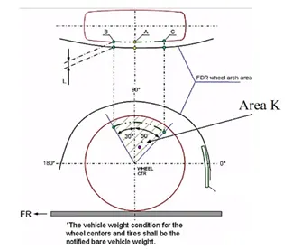
1.Japanese standards:
- Measure clearance L of the tire, hub, cap, and fender in three different positions within area K and produce a clearance check chart to validate.
- Clearance must be greater than 5 mm in all the three positions (i.e., at A, B, C from fender curvature)
- Wheel guard requirement: The value of 'a' shall be more than 5 mm at line 30* forward and 50* rearward from the central vertical axis of the wheel.
2.European standards:
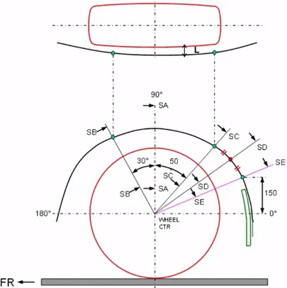
- According to european requirements the distance is measured at 5 different points.
- Measure CL L at sections SA-SA SB-SB SC-SC SD-SD SE-SE and produce CL check chart to validate.
- At all five sections the CL L value should be greater than 10 mm to satisfy the European regulations.
- ✓ Wheel guard reqmt: The value of 'a' shall be more than 5 mm at a line 30* forward and 50* rearward from the central vertical axis of axis of wheel.
3.US standards:
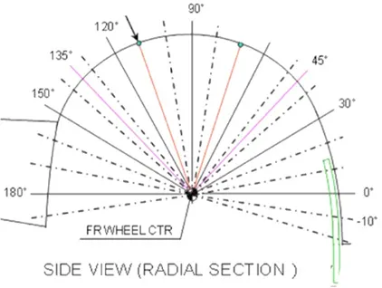
- The clearance ‘L’ at all positions (every 10o) from -20 deg to 180 deg should be greater than 5 mm to satisfy US regulations.
Why they have different requirements ?
- This is because of the road condition and also due to population density at the particular country.
- As in japan population density is high means speed limit will be low due to which at low speed the mud partical will spread slow so it have less distance ( 5mm) .
- While in europ population density is less means speed limit will be high due to which at high speed the mud partical will spread fast so it have more distance (10mm ) .
How I calculated.:
- We will start by constructing the points of measurements for the wheel arch area.
- first i used tthe point command to get center point of the outermost wheel .
- then created datam from that point.
- then i sketched the required specification according to the european standard and marked point where wheel arch and wheel line intersect.
- then used measure comond to measure the distance.
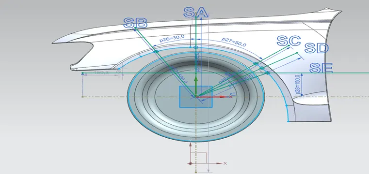
Measure CL L at sections SA SB SC SD SE and produce CL check chart to validate.
sections SA:
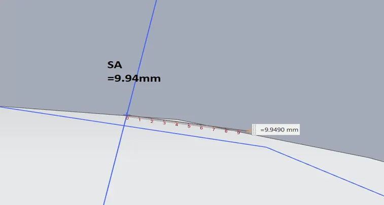
- CLEARANCE L at sections SA is 9.94 WHICH IS =10 mm from wheel to wheel archer
Section SB:
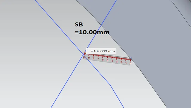
- CLEARANCE L at sections SB is 10 mm from wheel to wheel archer.
- Section SC:
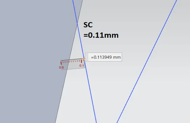
- CLEARANCE L at sections SC is -0.11 mm from wheel to wheel archer
Section SD:
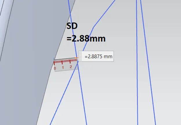
- CLEARANCE L at sections SD is -2.8mm from wheel to wheel archer.
Section SE:
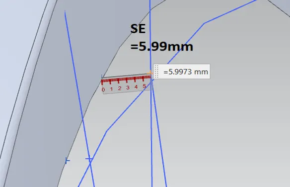
- CLEARANCE L at sections SE is -5.9mm from wheel to wheel archer.
Checking whether the front fender wheel arch meets the standards:
- Comparing the above-observed values with the required values.
-
Position/Section Observed Clearance Value (mm) Required Clearance Value (mm) Passes the Requirement SA 9.94 10 Fail SB 10.00 10 Pass SC 0.11 10 Fail SD 2.88 10 Fail SE 5.99 10 Fail
Conclusion:
The fender wheel arch area is calculated and the given fender design is failed in the wheel arch analysis according to the European regulation standard.