Fender Design - Wheel Arch Challenge
AIM: Examine the given fender wheel arch design to verify if the wheel arch of the fender meets the European standards.
Fender:
- A fender is the part of a car that protects and frames its wheels and keeps mud from splashing it.
- Its primary purpose is to prevent sand, mud, rocks, liquids, and other road spray from being thrown into the air by the rotating tire.
- Fenders are typically rigid and can be damaged by contact with the road surface.
- Front fenders are one example of such stiff body parts with small impact energy absorption capability.
- The fender's openings for the wheel wells tend to be much larger than the diameter of the tire, because they do not move with the tire suspension and consequently must be large enough to allow the full range of tire motion on the suspension without touching the interior of the wheel well.
Fender wheel arch:
- It is a curved part of the Fender positioned right above the Wheel.
- The Wheel Arch is designed such that it protects both the pedestrian and car cabin from mud, water rocks and other road spray
- Different countries have different wheel arch regulations in place, and the wheel arch design has to comply with them to be deemed usable in that country.
- For avoiding design alterations of the same vehicle to meet the different regulations in different countries, the maximum values of the concerned regulation parameters are taken into consideration for design purpose.
Fender wheel arc regulations:
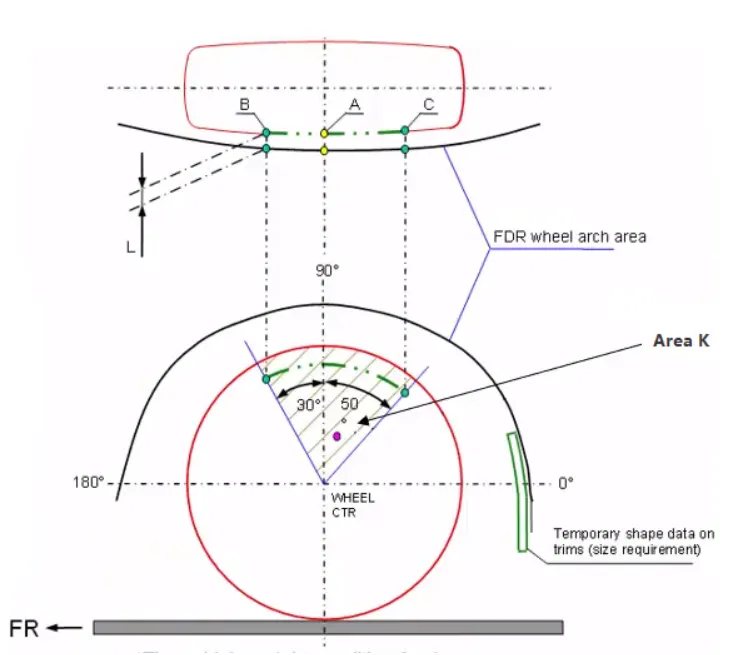
Europeon standards: The European regulation requires a pre determined clearance or a minimum distance of 10mm. to be maintained between the Fender (Front Quarter Panel) and the respective tyre at particular points(5 points/Sections to be exact) along the tyre profile as shown below.
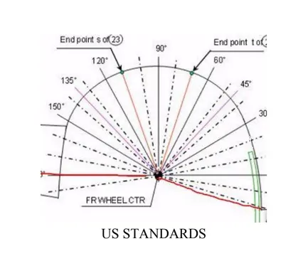
US standards: The American Standard requires the fender to be at a minimum distance of 10mm from the outer surface of the wheel at points at every 10 degrees from the -20degrees to 180degrees of the wheel center.
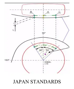
Japanese standards: The Japanese Standard requires the distance between the wheel and fender to be a minimum of 5mm at 3 points . Since the clearance at point 3 is 4.1mm. The part has failed to satisfy Japanese Wheel Arch Standards.
Fender design considerations:
- Drip area
- Wheel arch
- Baffel and ORVM mount area
- Front crash regulation and requirements
Fender design considerations:
- Drip area
- Wheel arch
- Baffel and ORVM mount area
- Front crash regulation and requiremen
Fender wheel arch calculation:
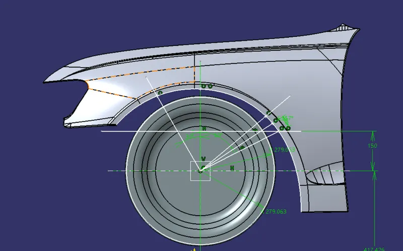
- According to the european standards the fender wheel arch clearence length will be 10mm. SA, SB, SC, SD, SE are the point on the wheel from where it is projected to the wheel arch to measure the distance.
- Create a plane parallel to the wheel surface with an offset of 0 distance.
- Now movie to the sketcher workbench and project the boundry of the wheel and the fender boundry on the plane which we created.
- Create a center point to the wheel boundry and giv ethe axis lines.
- Now draw the line with an angle of 30 degrees from the center point towards left side.
- Now draw the line witha an angle of 50 degrees from the centre point towards right side.
- Draw a line parallel to the horizontal axis towards up at a distance of 150mm from the centre axis.
- Now mark the points where the lines touching the fender boundry.
- Now draw a line passing from the centre point and the point where the 150 mm parallel line contacting the fender boundry.
- Draw the bisecting line between the 50 degrees line and the connecting line of center point and the parallel line contacting fender boundry. Mark the point where the bisecting line intersecting the fender boundry.
- Now project the points on the fender.
- Now measure the distance between the points on the plane and the points on the fender.
- Compare the values with the european standards.
Images:
Creating the plane
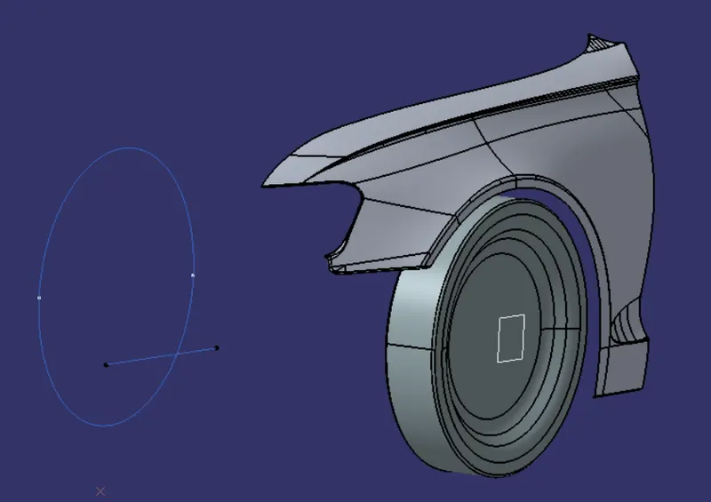
Extracting the boundries and creating the points according to the european standards.
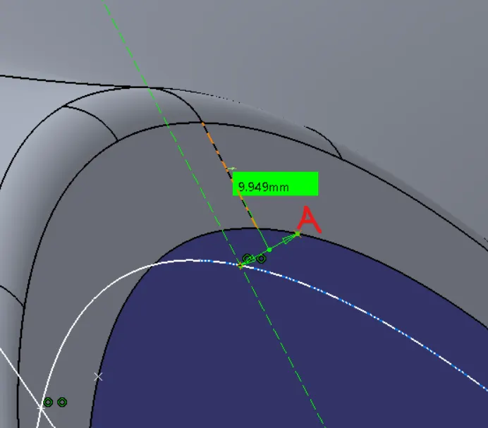
Now projecting the point SA on the fender and measure the distance
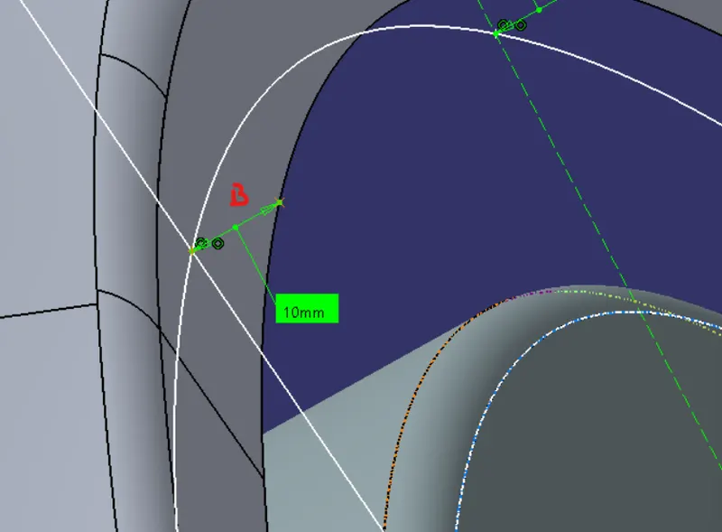
Now projecting the point SB on the fender and measure the distance
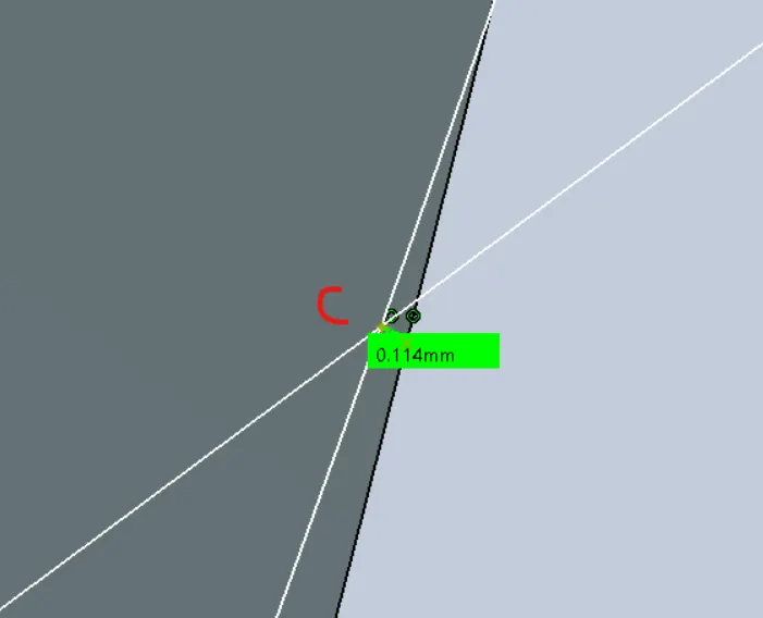
Now projecting the point SC on the fender and measure the distance
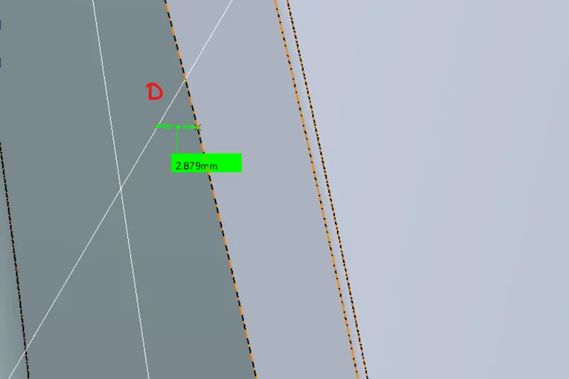
Now projecting the point SD on the fender and measure the distance
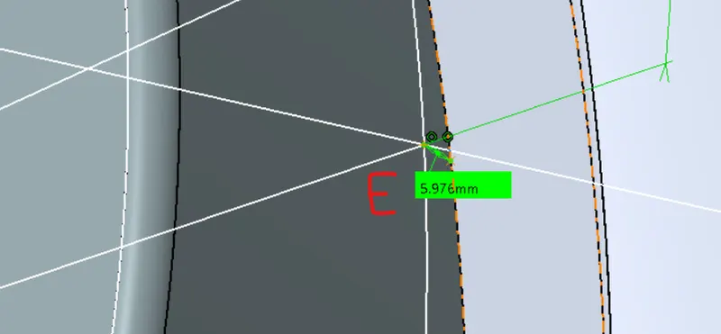
Now projecting the point SE on the fender and measure the distance
Observation tabular form mentioned below:
| Position | Required vertical Clearance Value (mm) (a) | Observed Clearance Value (mm) | The requirement Test |
| SA | 5 | 9.949 | Pass |
| SB | 5 | 10 | Pass |
| SC | 5 | 0.114 | Failed |
| SD | 5 | 2.879 | Failed |
| SE | 5 | 5.976 | Pass |
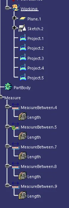
Tree:
Conclusion:
I will observed above calculation of the given fender wheel arch design will not pass the European standard in the position SC & SD has a verticle clearance less than 5mm which is the minimum requirement for European standards.