Fender Design - Wheel Arch Challenge
Fender Design - Wheel Arch Challenge
Analysis of the wheel arch area:
For pedestrian safety, the wheel should be within the fenders. Fenders are used to protect the engine compartment and pedestrians from getting hit from small gravel on the road. There are different standards for different countries. The countries’ vehicle regulatory body decides the standards for the vehicles in their subcontinent.
For Japan, it has Japan Automobile Standard Internalisation Centre (JASIC). According to JASIC:
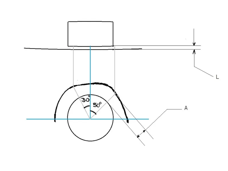
We have to take 3 points on the wheel and the fender at 0o, -30o and 50o with the vertical from the centre.
Gap distance A:
The distance between points lying on the wheel and their respective collinear point on the fender should have a minimum distance of 5mm.
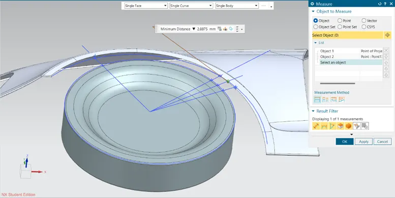
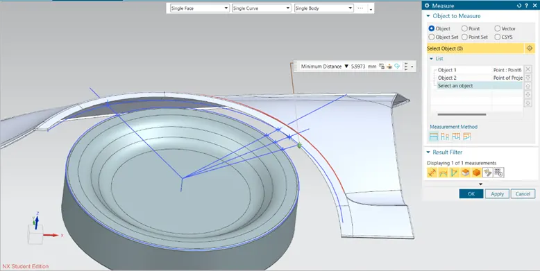
Project the points on the edge of the wheel arches onto the surface of the wheel arches. Now measure the points on the sketches with the projected points.
Gap distance L:
The distance between these points should be more than or equal to 5mm.
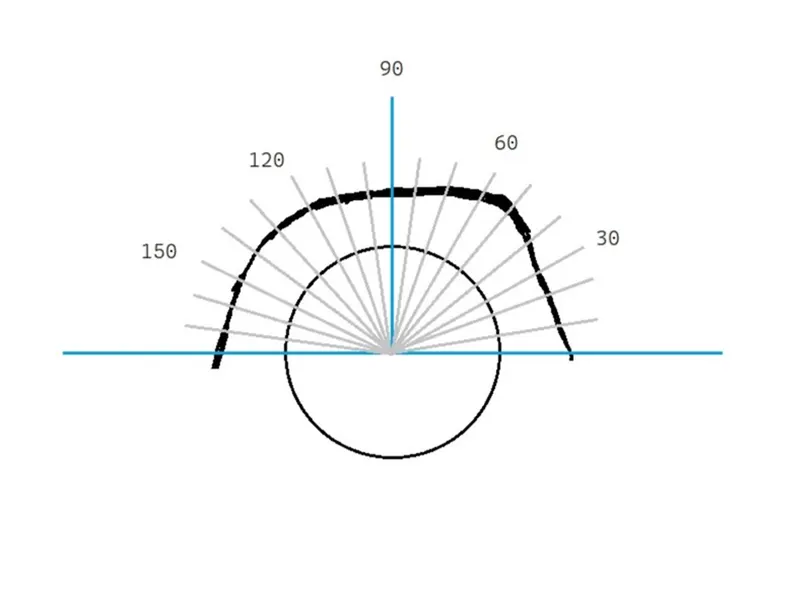
The National Highway Transportation Safety Administration (NHTSA) governs all the rules and regulation for the vehicle manufacturers who are building vehicles for the US market.
To calculate the gaps between the wheel and the wheel arch base, we have to mark point on the wheel and wheel arch area starting from 0o to 100o from the centre with respect to the horizontal.
Gap distance A should be more than or equal to 5 mm.
Gap distance L should be more than or equal to 5 mm.
For Europe, United Nations Economic Commission for Europe (UNECE) decides the regulations for the vehicle which are being launched.
According to UNECE, the gap between the distance between tyre’s outer edge and the fender’s inner surface must have a gap of 10mm at all the given points.
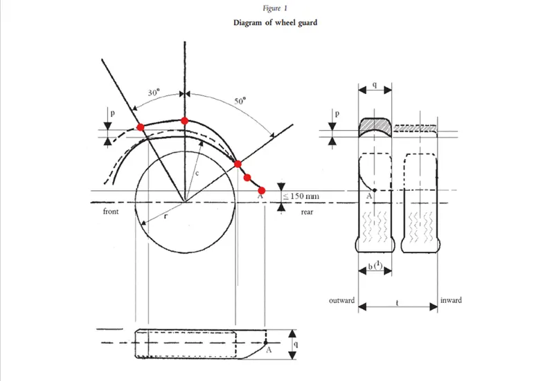
For the analysis of the fender arch gap, create a sketch and project the wheel outer edge and the wheel arch inner edge. From the centre, draw a line at 30o from the vertical. Draw another line at 50o from the vertical in the opposite side of the existing line. Create a point on the wheel arch inner edge at a distance of 150 mm from the horizontal.
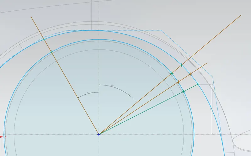
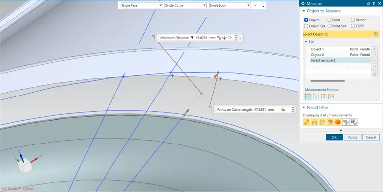
Testing for the gap A for the given specimen of the fender and the wheel:
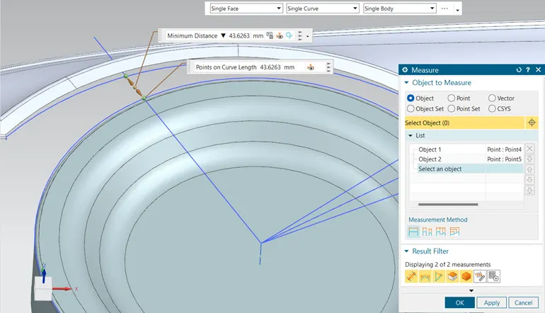
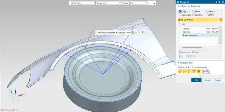
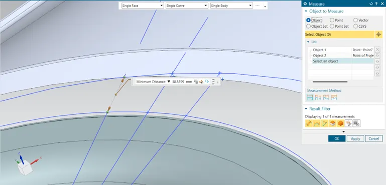
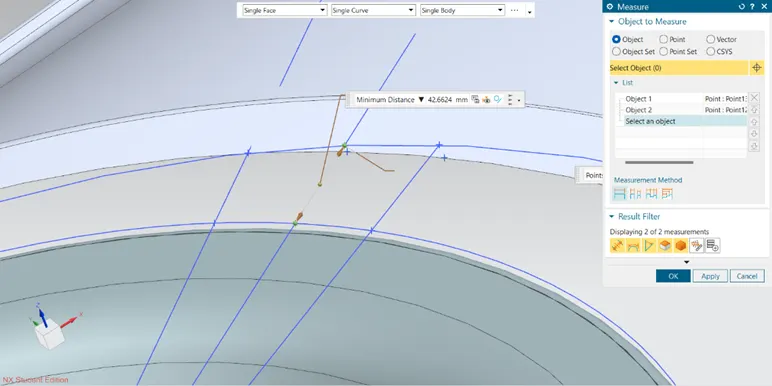
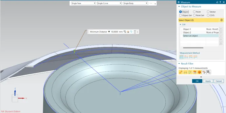
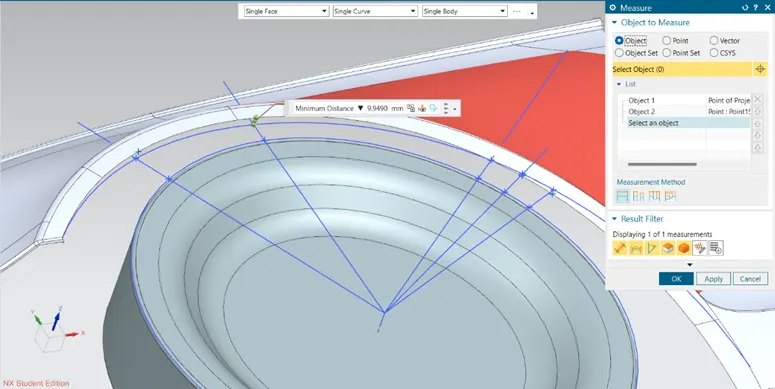
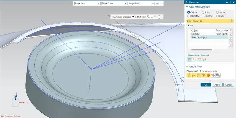
Testing for gap L for the given specimen of the fender and the wheel:
|
Reference line |
Gap A |
Gap L |
|
30o line anticlockwise |
43.62mm |
10.00mm |
|
0o line |
25.99mm |
09.95mm |
|
50o line clockwise |
38.35mm |
-0.11mm |
|
Bisecting line |
42.66mm |
-2.88mm |
|
150 mm from the horizontal |
47.62mm |
-5.99mm |
As per the data we obtained in the table, we can see that Gap A has been maintained very well as per the European standards.
But the gap L is not uniform and is not meeting the requirements of the European standards. It is maintained at the 30o line but at the rest of the points it is having a gap of <1mm. At point 150 mm from the horizontal, the distance is going in opposite direction of the required vector.
Thus, the designed fender doesn’t pass the European regulation.
Please find the report and part file in the attachment