Fender Design - Wheel Arch Challenge
FENDER DESIGN - WHEEL ARCH CALCULATION
OBJECTIVE:
Calculate the Wheel Arc area of European Standard and prove whether the car will pass the standards or Not.
INTRODUCTION:
The wheel arch is an arch-shaped cavity in the body of a vehicle, which houses a wheel. It has two important functions. It serves for the safety of pedestrians and other cars because the wheel is situated in the body of a vehicle. The second function is to protect the car from the sticky materials, such as mud, may adhere to the smooth outer tire surface, while smooth loose objects, such as stones, can become temporarily embedded in the tread grooves as the tire rolls over the ground. These materials can be ejected from the surface of the tire at high velocity as the tire imparts kinetic energy to the attached objects. For a vehicle moving forward, the top of the tire is rotating upward and forward and can throw objects into the air at other vehicles or pedestrians in front of the vehicle.
TYPES OF WHEEL ARCH REGULATIONS:
1. JAPAN REGULATIONS:
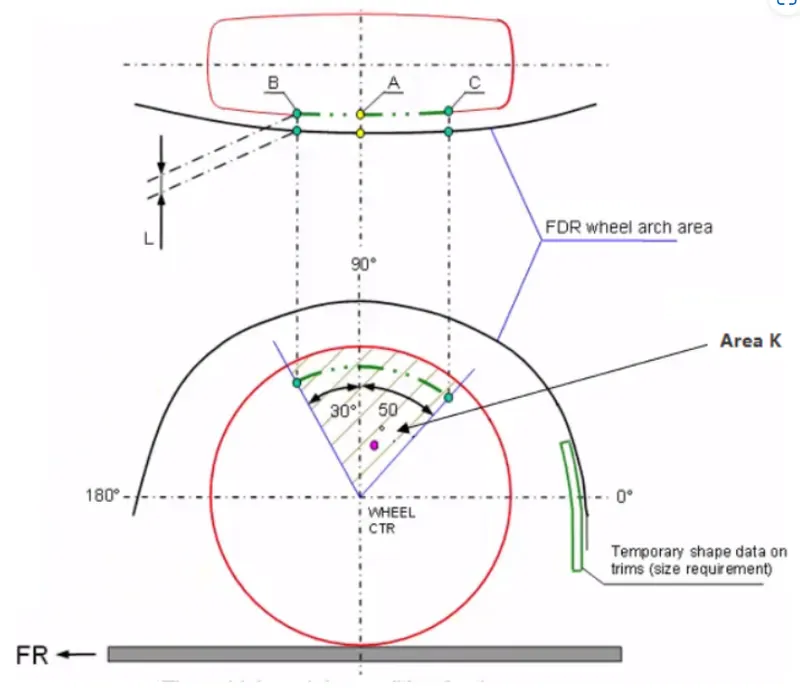
- The clearance ‘L’ for tire, hub, cap and fender is to be measured within area K and create clearance check chart to validate
- The value of L should be greater than 5mm at all positions
- Wheel guard requirement: The value of ‘a’ should be more than 5mm at line 30° forward and 50° rearwards from the central vertical axis of the wheel.
2. EUROPEAN REGULATIONS:
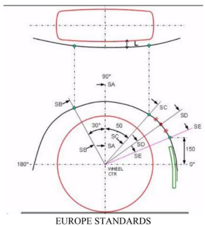
- The Clearance ‘L’ should be measured at sections SA-SA, SB-SB, SC-SC, SD-SD and SE-SE and create clearance check chart to validate
- At all the five sections the value of L should be greater than 10mm to satisfy the European Regulations
- Wheel guard requirement: The value of ‘a’ should be more than 5mm at line 30° forward and 50° rearwards from the central vertical axis of the wheel
3. US Regulations:
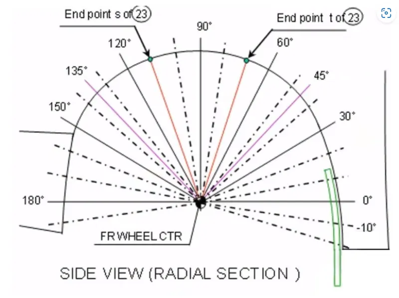
- Clearance ‘L’ is to be checked at all positions from -100° to 100° and create clearance check chart to validate
- The value of L should be greater than 5mm to satisfy the regulations
- Wheel guard requirement: The value of ‘a’ should be more than 5mm at line 30° forward and 50° rearwards from the central vertical axis of the wheel
Calculation of wheel arch area according to European Regulations
For calculation of clearance between Wheel Arch and Wheel we have to create a sketch on the outer most face of the wheel. The procedure of which is given below.
- A Datum Plane is created at the outermost face of the wheel
- The sketch is created on the new Datum Plane
- A Horizontal line is drawn across the centre of the wheel
- A perpendicular line SA is dropped at the centre of the wheel
- Two lines SB and SC are created at 30° forward of SA and 50° rearward of SA respectively
- A point is created 150mm vertically above the centre line
- A line SE is drawn from the wheel centre and passes from the point created
- Another line SD is drawn from the centre of the wheel and in the middle of lines SC and SE
Analysis:
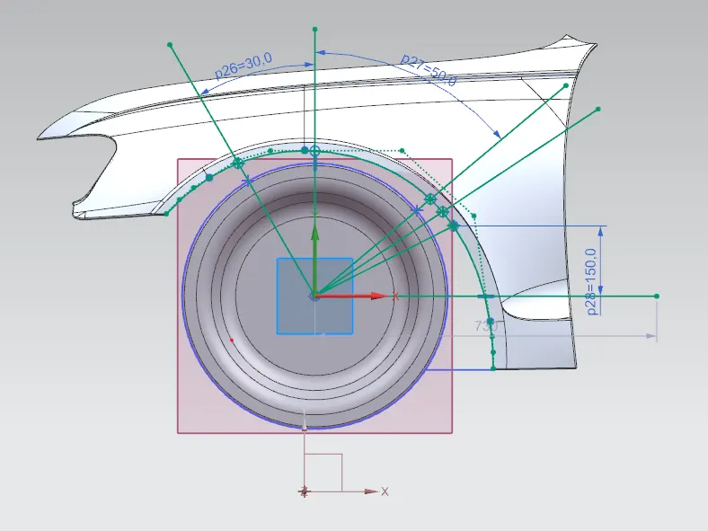
Obtaining the clearance L at the designated 5 points
The clearance distance 'L' is calculated at points SA-SA, SB-SB, SC-SC, SD-SD and SE-SE, which should be greater than or equal to 10mm
(a) Clearance 'L' at SA-SA
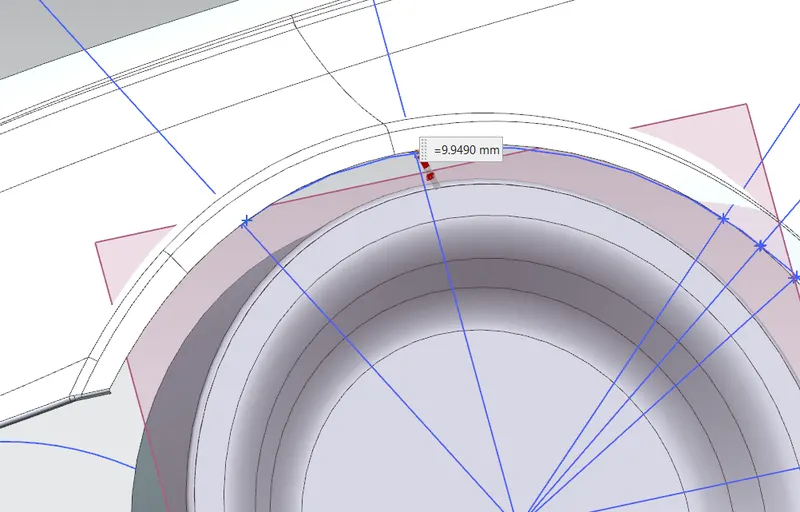
L = 9.9490mm
(b) Clearance 'L' at SB-SB
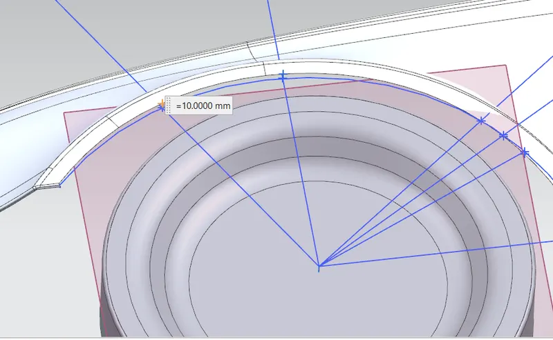
L = 10.00mm
(c) Clearance 'L' at SC-SC
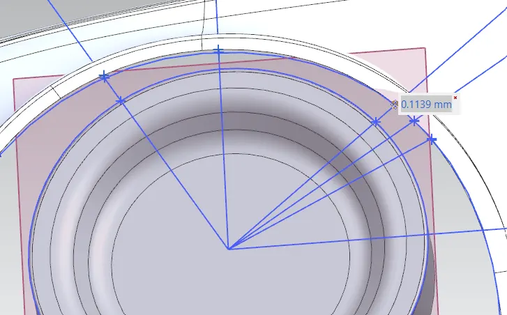
L = 0.1139mm
(d) Clearance 'L' at SD-SD
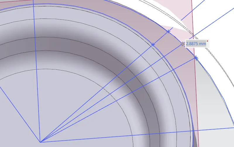
L = 2.8875mm
(e) Clearance 'L' at SE-SE
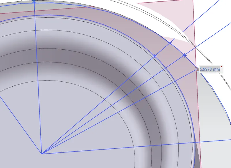
L = - 5.9973mm
Measuring the clearance vlaue'a' for Wheel Guard Requirement
(a) Clearance 'a' at 30° line SB
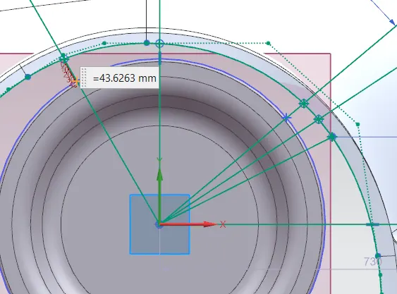
a = 43.6263mm
(b) Clearance 'a' at 50° line SC
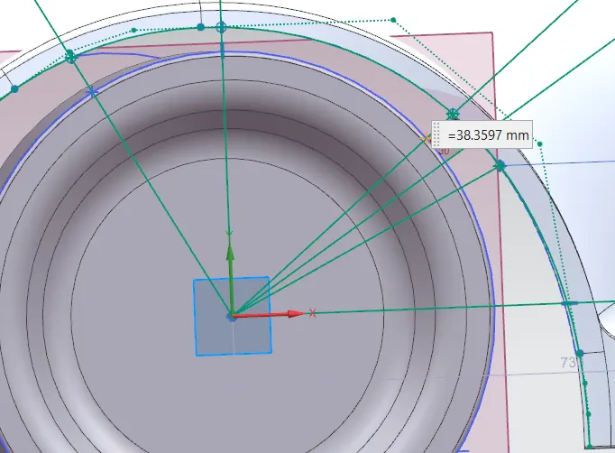
a = 38.3597mm
Conclusion:
| Section | Length (>10mm) | Result | a (>5mm) | Result |
| SA - SA | 9.9490mm | Fail | 43.6263mm | Pass |
| SB - SB | 10.00mm | Pass | ||
| SC - SC | 0.1139mm | Fail | 38.3597mm | Pass |
| SD - SD | 2.8875mm | Fail | ||
| SE - SE | 5.9973mm | Fail |
From the above results we can conclude that the Fender does not pass the European Regulations, as the minimum clearance L between the Fennder Wheel Arch and Wheel for vehicle and pedestrian safety is 10mm and this design does not meet the requirement.