Fender Design Challenge
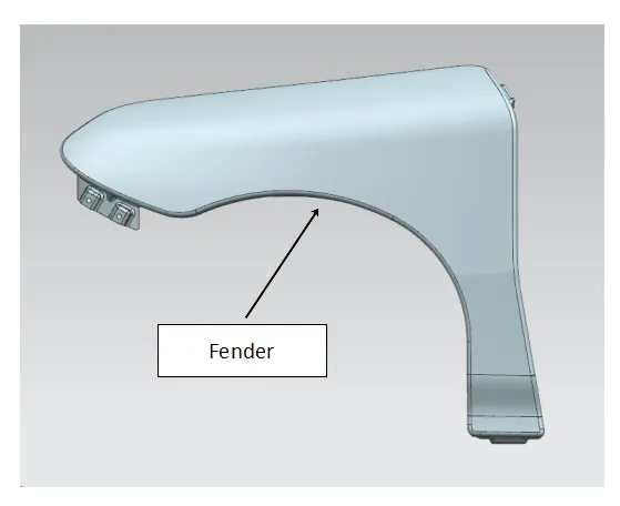
FENDER :
- It is a part of the vehicle that frames a wheel.
- The primary purpose of the fender is to prevent sand, mud, rocks, liquids, and other road spray from being thrown into the air by the moving vehicle tyres and hurl them in all directions. Therefore, fenders are provided to prevent any injuries to pedestrians and contain the motion of these particles.
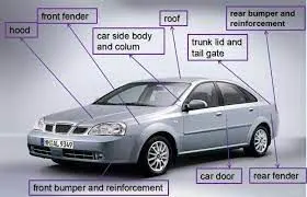
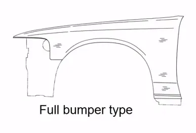
There are two types of front fenders
a) Full bumper type
b) Half bumper type
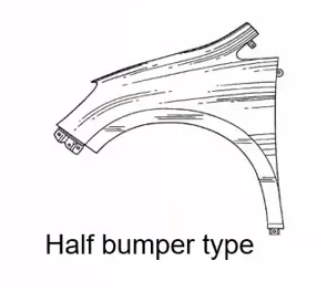
The half bumper type is generally used now days due to its easy and efficient manufacturability.
FENDER DESIGN:
- The fender design includes fender skirts for enclosing the outside edge of the wheel well, and stylized pontoon fenders for exposed fenders.
FENDER MOUNTING POINTS :
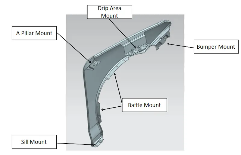
- There are five mounting points in a Fender. They are
a) Bumper
b) Baffle
c) Sill
d) A Pillar
e) Drip Area.
MANUFACTURING PROCESS:
- The manufacturing process of fender begins with sheetmetal which cut into particular size of sheets known as blank.
- Blank becomes the workpiece which is reshaped in the metal reforming process.
- The metal reforming process used for Fender is stamping
STAMPING :
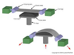
- It is also called as pressing and involves placing flat sheet metal, in either coil or blank form, into a stamping press. In the press, a tool and die surface form the metal into the desired shape. Punching, blanking, bending, coining, embossing, and flanging are all stamping techniques used to shape the metal.
- There are basically only three components to sheet metal stamping—the sheet metal, die, and press machine—but any single part can require multiple steps to arrive at its final form. The following process explains a few common processes that might occur during metal stamping.
- Forming: Forming describes the process of transforming the flat metal into another shape by applying force. It is accomplished in one of several ways, depending on the design specifications for the part. With a series of operations, the metal can be altered from a relatively simple shape into a complex one.
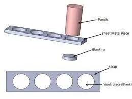
- Blanking: Blanking is the most basic technique and initiates when the sheet or blank is fed into the press where the die cuts out the desired shape. The resulting piece is called a blank. The blank may be the desired part, also known as a fully finished blank, or it may continue to the subsequent step of forming.
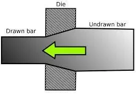
- Drawing: Drawing is a more complicated operation and is how vessels or deep depressions are formed. Tension is used to carefully draw the material into a cavity to change its shape. Though the material might stretch while it’s drawn, technicians try to avoid stretching as much as possible to keep the material intact. Sinks, cooking equipment, and oil pans for vehicles are usually made with drawing.
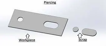
- Piercing: Piercing is almost the opposite of blanking, but instead of saving the blanks, technicians use the material around the outside of the punched area. As an example, think of cutting biscuits from a rolled-out circle of dough. During blanking, the biscuits are saved; during piercing, on the other hand, the biscuits are discarded, and the hole-riddled remains are the desired outcome.
DESIGN PARAMETERS:
- The design parameters taken into consideration while designing the fender are
a) Master section:
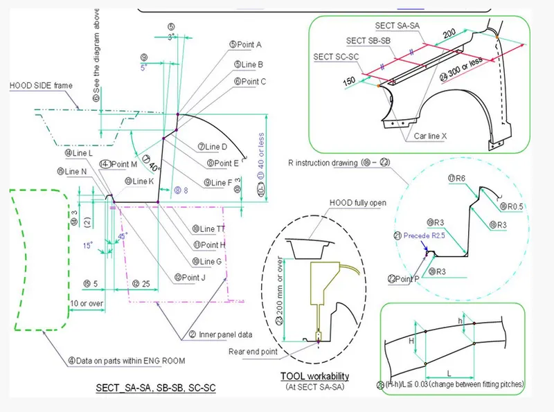
The given master section is followed and design is made in accordance with the master section.
b) Fillet Radius :
- The fillet radius is provided as mentioned in master section.
- If the fillet radius is not provided to for certain section. Then according to basic rule of sheetmetal design the fillet radius is given as 3 + T, wherein T is thickness of the sheet.
c) Gap:
- The gap between the fillets and engineering features (emboss, hole etc.) is maintained more than 5mm.
d) Sharp Corners:
- The sharp corners are avoided and for the sharp or abrupt edges, relief corners or fillets are provided. The fillet radius is maintained as mentioned above.
e) Dart or Rib :
- The darts or ribs are provided to sheetmetal section to provide strength to region.
- The darts or ribs are provided to region where the required.
DESIGNED FENDER:
MOUNTING AREAS OF DESIGNED FENDER:
CONCLUSION:
- The designed parameters and master section was followed and the fender was designed successfully.