Fender Design Challenge
Aim:
To design the fendor of a car using UG NX.
Objectives:
01.
To study the fendor design.
Introduction:
Fender is a part of a vehicle which frames a wheel and prevents from the sticky and hard substance such as mud, sand, rock, etc. Sticky materials such as mud may adhere to the smooth outer tire surface, while smooth loose objects such as stones can become temporarily embedded in the tread grooves as the tire rolls over the ground. These materials can be ejected from the surface of the tire at high velocity as the tire imparts kinetic energy to the attached objects. For a vehicle moving forward, the top of the tire is rotating upward and forward and can throw objects into the air at other vehicles or pedestrians in front of the vehicle. Fenders are typically rigid and can be damaged by contact with the road surface. Instead, flexible mud flaps are used close to the ground where contact may be possible.
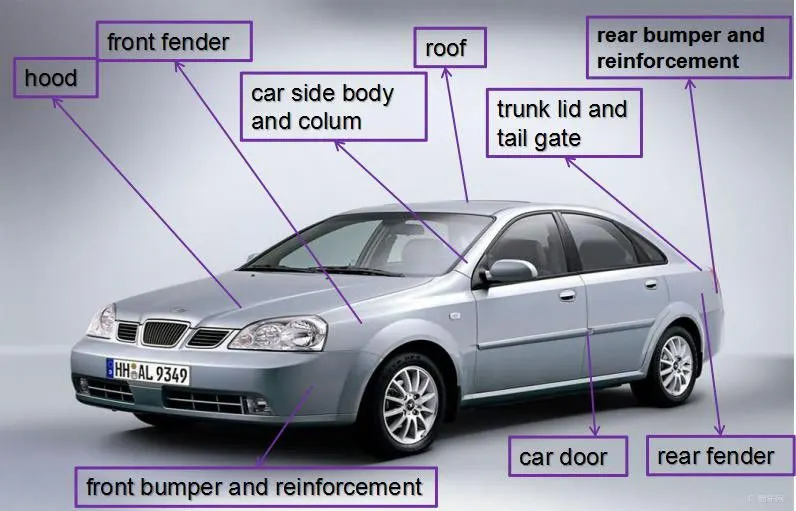
Fig01: BIW components of a car.
Problem Statement:
Follow the given Master section to create the Drip Area
Fig02: Design of fendor of a car.
For the Sill, Bumper, Baffle (Splash), and A-Pillar mount create your own design according to the Engineering standard that you learned.
Prepare a report with all the relevant images included for the mounting points created.
Solution:
First of all let's study about the fendor and it's mountings.
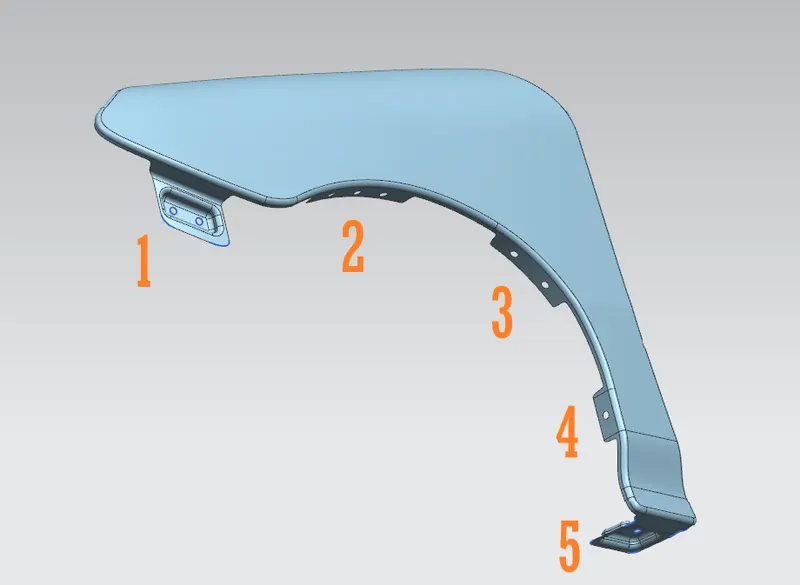
Fig03: Fendor and it's mountings.
01: Bumper mounting of the fendor.
02. Baffle mounting of the fendor.
03. Baffle mounting of the fendor.
04. Baffle mounting of the fendor.
05. Sill mounting of the fendor.
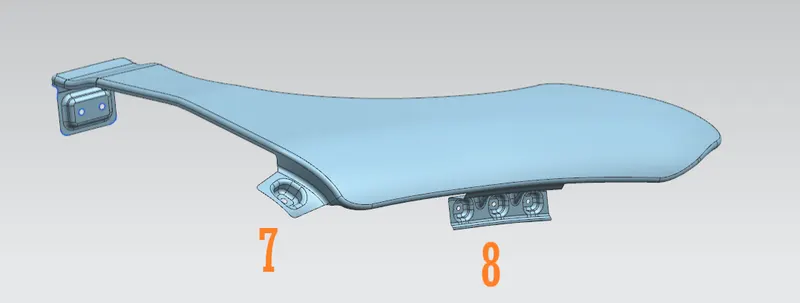
Fig04: Fendor and it's mountings.
07. A-pillar mounting of the fendor.
08. Drip mounting of the fendor.
A]
Drip mounting:
Now let's discuss the design of the drip mounting of the fendor.
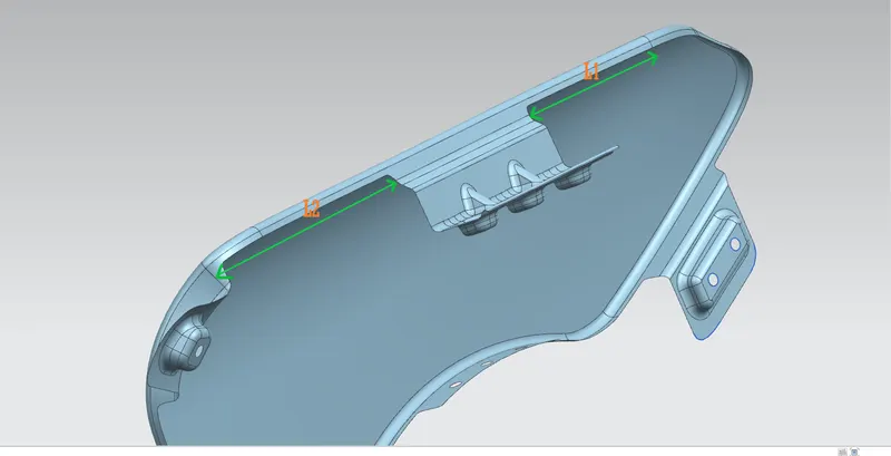
Fig05: Drip mounting design consideratiions-I.
Drip is the joining between the fendor and the engine compartment.
L1 = 150 mm.
L2 = 200 mm.
The minimum length of L1 must be 150 mm from the end of the headlight assembly.
And the length of L2 varies from 200 mm to 250 mm (depending upon the cowl provision provided for the wiper motor and it's components) from the end of A-pillar. The lesser the distance of L2 greater is the space we get to design the drip mounting for the fendor.
In simple words L1 is the length of space left for mounting of headlight assembly whereas L2 is the length of space left for the mounting of cowl of the motor assembly.
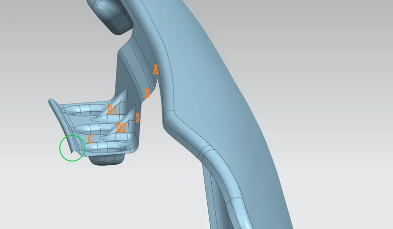
Fig06: Drip mounting design consideratiions-II.
The drip mounting consists of surfaces A, B and C.
The A surface is inclined at 3° i. e. minimum opening angle because that's how tool works and the width must be 6 mm in order to maintain the overall length of the drip mounting.
To prevent the visibility of the inside components of the car from outside, the B surface is inclined at 40° from horizontal. The embosses of the drip area must align with the provisions on the bracket between the fendor and engine compartment, for fastening the fendor to the engine compartment maintaining the width of 8 mm to maintain overall length of drip mounting (less than 60 mm) in order to avoid the spring back effect.
The S surface must be extended downward at 5° such that the overall depth of the drip mounting must not be greater 40 mm to ensure the capabilities of the tooling while punching the holes in the drip area, most of the tools cannot produce holes at the depth of distances greater than 40 mm.
The end emboss of the C surface must be extended along it's width such that, the outermost end of the drip area must be at 10 mm from the engine. In simple words there must be clearance of 10 mm between drip and the engine of the car.
The dimensions of the features marked with green circle are calculated by using pythagoras theorem and design accordingly. This is design in order to increase the strength of the drip area.
Embosses provided are for the mounting of the sheet metal component on the metal frame with help of fastners.
The number of embosses and the diameter of the holes depends upon the design requirements. Important design consideration while designing holes is that, there must be atleast 5 mm of the space around the hole to reduce the stress concentration.
The minimum radius of the of the blend must 3+t (t = thickness of metal sheet).
As shown in fig05 D1 and D2 are the darts provided on the drip mounting, dart is a narrow ridge of metal used for reinforcement on a flange of a part. The dart is formed into the edge of the flange and the part to increase it's strength.
B]
Bumper mounting:
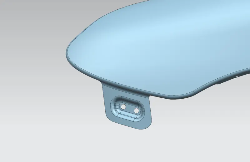
Fig07: Bumper mounting of fendor.
A bumper is a structure attached to or integrated with the front and rear ends of a vehicle, in a front it is integrated with the fendor, to absorb impact in a minor collision, ideally minimizing repair costs
Emboss is provided in order to increase the strength of the mounting. The bumper is mounted with help of fastners.
C]
Baffle mountings:
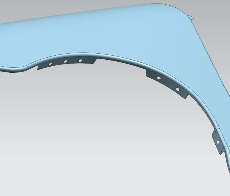
Fig08: Baffle mountings of fendor.
Baffle is plasric component mounted on baffle mountings of the fendor between fendor and typr of a car.
Plastic is mainly used in order to reduce the weight of the component itself and to prevent the corrosion and wear and tear of the fendor due to encountered granules across the road.
Baffle is mounted with the help of plastic pins and bushes therefore no embosses are allotted for fastners.
The radius of the blends across the corners of the fendor is 2.5 mm in order to avoid the sharp corners to enhance the pedestrian safety.
In order to improve the performance of a car for NVH test additional baffles are provided in some cases, for that additional baffle mountings are required.
D]
Sill mounting:
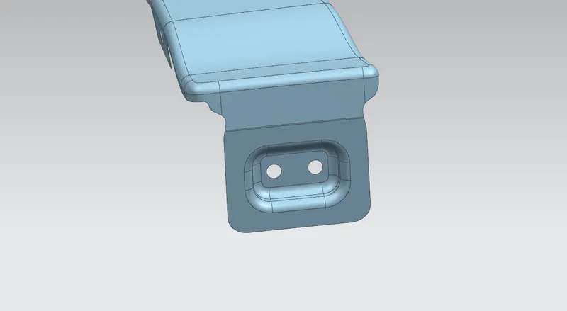
Fig09: Sill mounting of fendor.
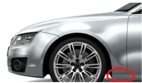
Fig10: Sill region for the sill mounting of fendor.
This area comes under the car where the fendor is mounted on it with help of fastners on the sill mounting.
E]
A-pillar mounting:
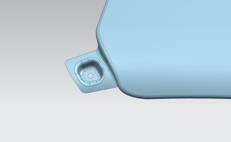
Fig11: A-pillar mounting of fendor.
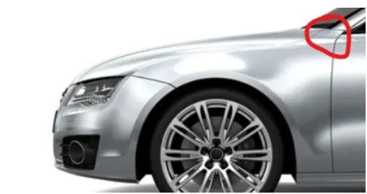
Fig12: Region for the A-pillar mounting of fendor.
The A-pillar mounting is provided just behind the wiper motor assembly's cowl of a car. Where the A-pillar is mounted on the A-pillar mounting of the fendor with the help of fastners.
Results:
Provided skin of the fendor is a Class-A surface i. e. outermost surface of the component which is very important asthetically therefore we must apply the thickness to the component towards inward direction.
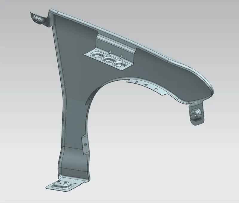
Fig13: Fendor with assigned thickness (075 mm) to it towards direction .
Conclusion:
The fendor is designed with the various design considerations and parameters which are applicable in real life applications by following the master sketch and given styling surface.