Fender Design Challenge
DESIGN OF A FRONT FENDER USING CATIA V5
OBJECTIVE:
- To design and develop a Fender (and its mounting flanges) from the given skin data, master section, and design parameters using CATIA V5
- To explain the terminology involved in the design process of a Fender
- To explain the manufacturing processes employed to create a Fender
INTRODUCTION:
Fender: is one of the closure components of an automobile. It is the curved part that covers and shields the wheel side of the body of a vehicle. There are four fenders in a car, one for each wheel. Its major purpose is to prevent road debris from being thrown by the rotating tire either inwards into the vehicle body or outwards to the surroundings causing damage. It also acts as a shield from the rotating tire whenever there is a collision with a pedestrian or other vehicles. The fender's opening forms the wheel well which is much larger than the diameter of the tire as it is not a moving component and has to allow for the full range of motion of the tire and its suspension. It protects the components in the engine compartment from atmospheric aspects and other damage. Over the years, it became a major styling component in highlighting the aesthetics of the vehicle and more recently it is being used as an active structure in improving the safety standards of a vehicle. Fenders are usually of two types depending on the area of coverage - full bumper type and half bumper type.
Fig. Image of a Full bumper-type front left Fender of a Car
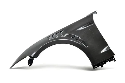
Fig. Image of a half-bumper-type front left fender of a Ford Mustang
DESIGN:
The Fender Design can be approached as depicted in the flowchart below
- Study the given information and prepare the given skin data
- Develop the shape of the Fender from the given skin data, and provided design parameters
- Design the necessary flanges, embossed, and cut-outs for the Fender
Given Information:
The given data and design parameters are as follows:
- Master Section for Drip Area Flange:
- Other Mounting flanges are designed considering engineering standards
- Fender Thickness information is not given so,
- Assumed Thickness = 0.75mm
Mounting Points:
Being a closure component, the fender is expected to be firmly attached to the body of the vehicle. Hence, multiple mounting points are provided for the fender to be fastened to the body. Flanges are designed on the fender at the respective mounting points for the purpose of fastening.
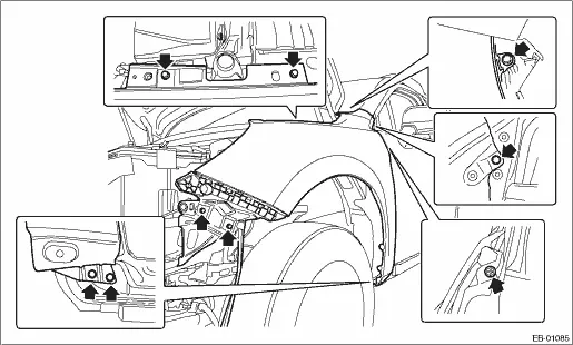
Fig. Image of the different fastening points of a Subaru Legacy front fender
The Front Fender is designed with flanges at multiple mounting points as mentioned below:
- Drip
- Bumper
- Baffle
- Sill
- Body
Drip: is the region where the front fender is attached to the engine compartment of the vehicle. This is the most important mounting region as the maximum area of support can be achieved. There are certain design parameters to be followed for the Drip Area Flange for proper mounting of the fender and to avoid intersection with components inside the engine compartment. As the drip area flange is usually long, ribs are provided for additional stiffness.
Fig. Close-up Image of Drip Area Flange
Bumper: is the region where the front fender is attached to the front bumper of the vehicle.
Fig. Close-up Image of Bumper Area Flange
Baffle: is the region where the front fender is attached to the wheel well area of the vehicle.
Fig. Close-up Image of Baffle Area Flanges
Sill: is the region where the front fender is attached to the bottom part of the sill portion of the vehicle body
Fig. Close-up Image of Sill Area Flange
Body/A-pillar: is the region where the front fender is attached to the A-pillar of the vehicle body. Sometimes instead of the A-pillar, the front fender is attached on the Cowl region where the ORVM is fixed.
Fig. Close-up Image of Body/A-pillar Area Flange
Fender Images:
Fig. Outer View of Fender
Fig. Inner View of Fender
Manufacturing Processes employed in creating the Fender:
- Deep Drawing: is a sheet metal forming process wherein a sheet metal blank is converted into a cup-shape by pressing the sheet metal in the center with a circular punch fitting into a cup-shaped die. During the process, the sheet metal is subjected to a complicated pattern of stress making it one of the most difficult sheet metal operations. The portion of the sheet between the punch and the die wall is subjected to pure tension, whereas the portion at the bottom is subjected to both tension and bending. The outer end portion of the sheet between the die blocks is subjected to circumferential compressive stress and buckling. Here, the basic shape of the Fender Inner Panel is achieved from deep drawing.
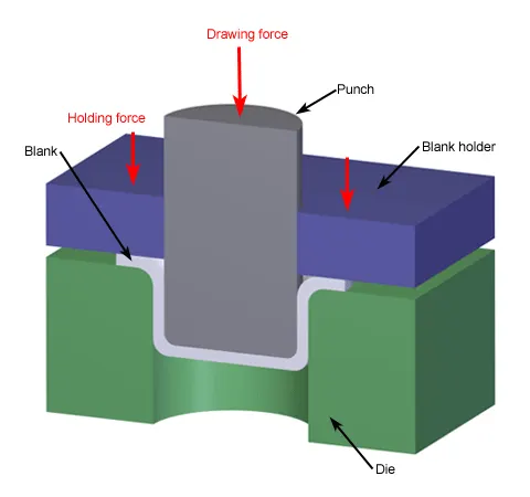
Fig. Image of a Deep Drawing operation - Bending: is a sheet metal forming process in which a sheet metal is deformed into a V, U, or channel shape. The material is subjected to both tensile and compressive forces. Usually, the sheet metal springs back to regain its original shape due to the residual forces after the removal of the deforming forces. This springback effect depends on the material and the operation performed. Hence, the sheet metal should be bent more than required to achieve the desired shape. The same operation can also be achieved with the help of a mechanism called a press brake wherein the sheet metal is forced against a die with the help of a punch. Air Bending, Bottoming, and Coining are the three types of bending operations that can be performed on a press bake, each defined by the relationship of the end tool position to the thickness of the material.
Fig. Image of two types of Sheet metal Bending operations - Embossing: is a sheet metal forming process in which impressions are made on a sheet metal blank such that the thickness remains uniform throughout the sheet even after embossing has been done. It is a form of pressing operation where not much force is needed. The blank is kept on the bottom half of the die and the stroke of the punch is adjusted so that, when it moves down to its lowest position, it leaves a uniform clearance between the impressions carved in the punch and the die which is equal to the thickness of the sheet being embossed. As a result, the design is transferred onto the sheet by bending the sheet up or down without altering its thickness. Here, embosses are provided on the Inner Panel to both increase the structural rigidity as well as to transfer the impact forces towards the hinges.
Fig. Image of an Embossing operation - Blanking: is a form of sheet metal punching process in which a sheet metal is kept on a die and is sheared or pierced by a punch of the desired profile. Here, the punched-out part is called a blank and usually requires no further machining. This process is ambiguous with punching. Here, the outer shapes of both the Inner and Outer Panels as well as the corner relief for hemming of the Outer Panel are obtained by this process.
Fig. Image of a Blanking operation - Punching: is a form of sheet metal punching process in which a punch is forced through a sheet metal to create a hole of desired profile. Here, the part of the blank which is punched is the workpiece and the punched-out part is scrap. Here, this process is used for removing material in the form of cut-outs and holes wherever required on the Inner Panel of the Fender.
Fig. Image of a Punching operation
CONCLUSION:
- Hence, a Front Fender is designed and developed from the given surface data and according to the given design parameters.