FENDER DESIGN CHALLENGE
Fender Design
Objective
Design the front fender from the given skin data and use the master section provided to construct the dip mounting.
Design Parameters
Master Section for the dip mounting.
Hole diameter = 5mm
Minimum flat surface for fastening = 10mm
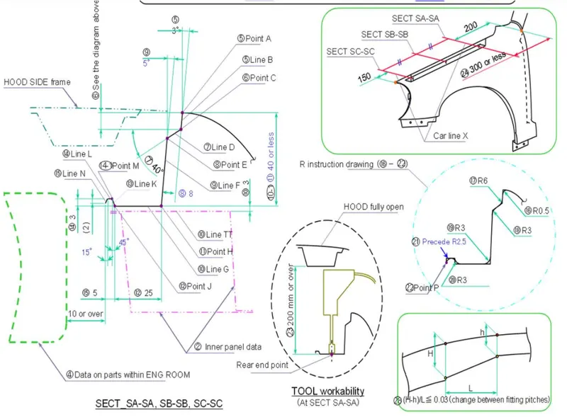
The figure includes the master section and the permissible location for the design of Dip mounting.
Required Mountings
Typically, there are five mountings provided for a front fender. They are,
- Dip mounting
- A pillar mounting
- Sill mounting
- Bumper mounting
- Baffle mounting
Dip mounting
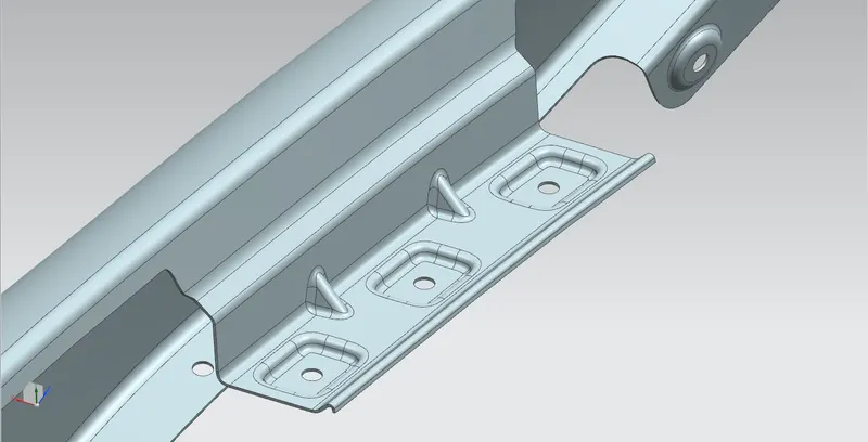
For the Dip mounting we should extend the flange according to the master section. Always make sure that the fastening region is flat. And for the ease of manufacturing and accessibility use single vector direction for the adjacent holes. The master section is decided by considering some factors like avoiding the visibility of engine compartment or other inner structures through the gap, provide enough strength for mounting, reduce spring back effects at the bends etc. We can also add ribs to improve the stiffness of the sheet.
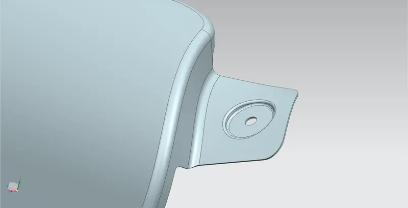
A pillar mounting
Sill mounting
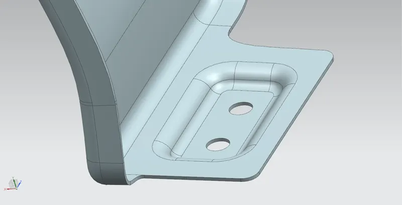
Bumper mounting
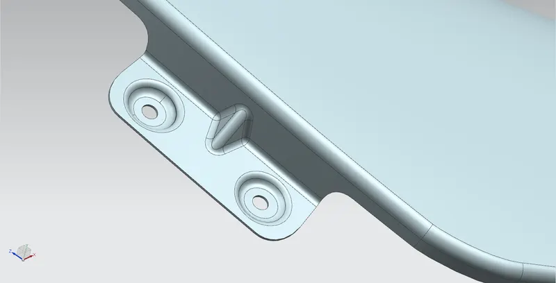
Baffle mounting
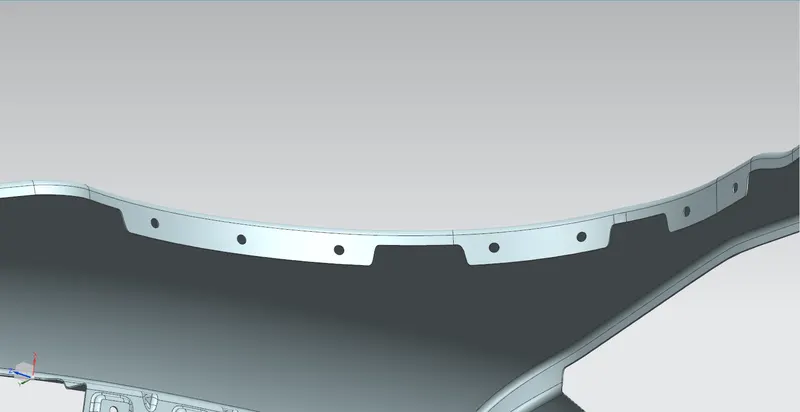
For Baffle mounting we use plastic fastener rivet clips. So it is not essential to provide perfect flat surfaces for the fastening regions.
Result
Designed front fender by the given parameters like skin data, master section for the dip mounting etc using Siemens NX.
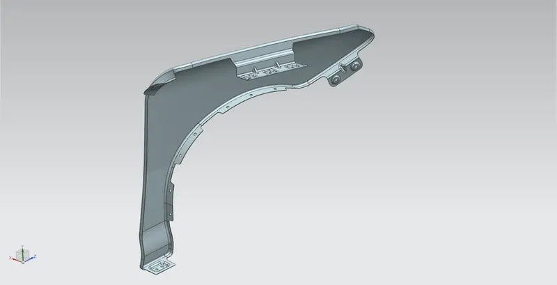
Link for fender part file: https://drive.google.com/file/d/1byXj8lW3XJk2E_uf7ocC2sqFdBBhISX-/view?usp=sharing
Link for fender IGS file: https://drive.google.com/file/d/1o55l2alG3gEK53_iFSLDItM88kjhT8nK/view?usp=sharing