BIW Exterior: Front Fender Design
OBJECTIVE
The objective is to design Drip Area and Mounting points for the Fender and also to provide appropriate attachment points for Sill Mount, Bumper Mount and A Pillar Mount
REPORT
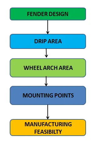
Design Methodology
The Fender sits above the Wheel which protects it from chipping effect of stones and debris and also acts as a connecting point for various exterior structures like hood, Engine compartment, A Pillar , Sill and Bumper.
The Fender used nowadays are Half Bumper type which reduces the cost of the Sheet Metal Blank drastically and also provides considerable weight reduction
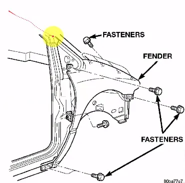
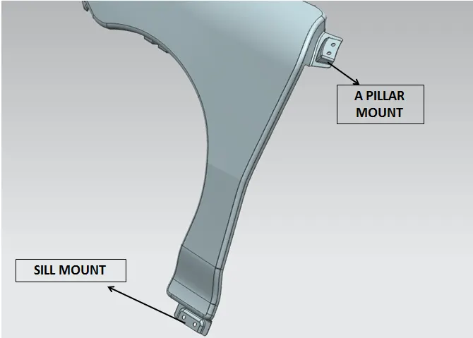
Img 1)Fender with mounting points
Fender Design Methodology is vital to ensure proper mounting of Wheel and Engine Compartment and two important areas to consider are
- Drip Area
- Wheel Arch
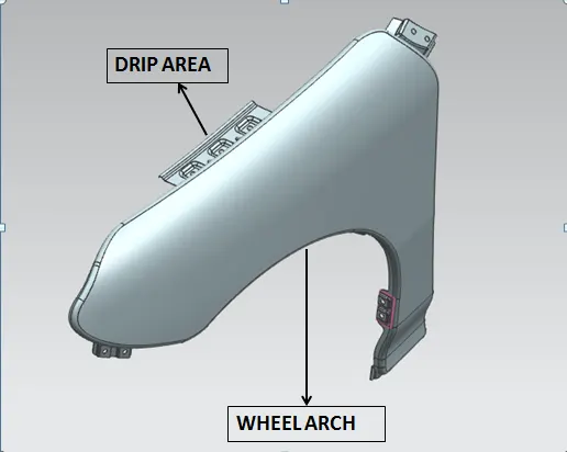
Fender with Drip area and other mounting points
WHEEL ARCH
Wheels are alligned inside the fender to reduce the chipping effect and clearance value is specified based on the standard regulations of different regions based on the road drive considerations
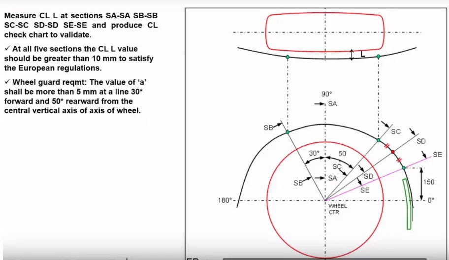
Wheel Arch guidelines for European Standards
DRIP AREA
- Drip Area allows to connect the fender with the engine compartment and it is a protruding flange from the fender skin.
- Based on the cowl part and front headlamp ,drip area is designed and usually has mounting points with suitable forward and rearward clearance from the car line.
- Considering the Tool Workability factor the depth of the Flange is limited within 40 mm and clearance of 10mm is ensured for engine room
- The notable consideration while providing Flange length is to avoid the visibiliy of the consumers on Engine room.
- Pedestrian Safery standard are also taken into consideration and usually cutline should have minimum of 47 mm based on the Side Reference Line to calculate the wrap around distance
- A L Shaped baracket is provided below the drip area to avoid the spring back effect
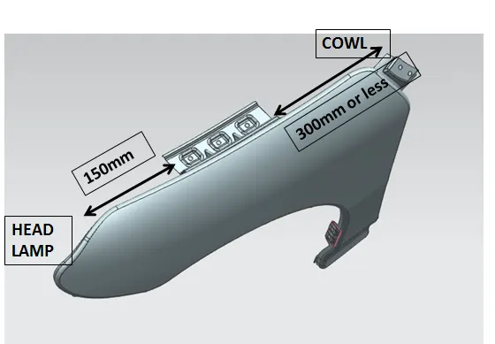
Design Consideration and guidelines for Drip Area Length
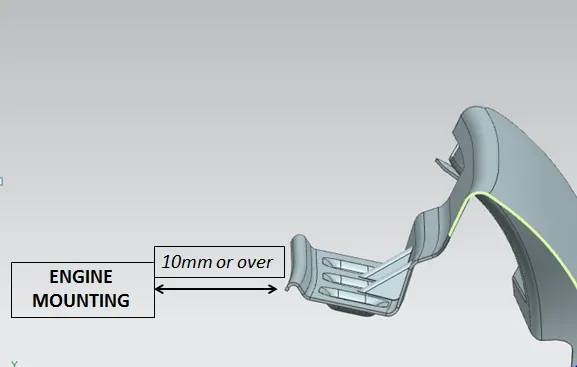
Clearance for Engine Room
MOUNTING POINTS
- Mounting points are provided with suitable emboss and some mounting areas are provided with ribs to increase the strength of the flange.
- A Flat surfaced emboss with mounting points hole which has a minumum of 5mm surface around it is ensured
- The position of the mounting points depends on the counterpart and the mounting points should have smooth curvature cut for feasible manufacturing
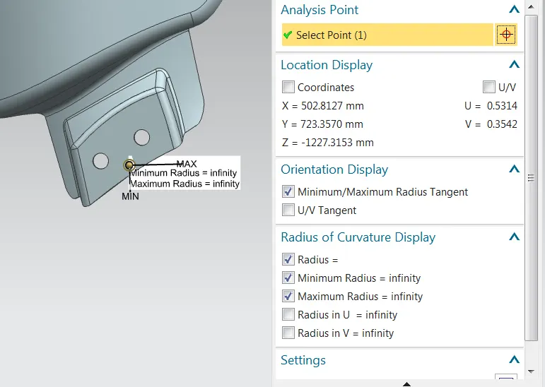
Flat faced emboss for A pillar Mounting
The Mounting points provided in this design apart from drip area are
- Bumper Mounting
- Sill Mounting
- A Pillar Mounting
- Mounting points for baffles
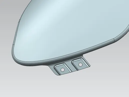
Bumper Mounting
OPERATIONS USED
After obtaining the fender skin , The drip area is calculated and the flange is designed as per the design considerations along with the creation of above mentioned mounting points. The commands used in NX are
- Offset Curve in Face
- Surface Curve
- Law Extension
- Intersection Curves
- Bridge Curve
- Trim Sheet
- Dart
- Emboss
- Face Blend
- Edge Blend
- Thicken
All the Sketches used are constrained and curves are constrained to suitable faces.
The Tree structures are classified with feature groups for feasible workaround in future
Curves, Sketches and Datum Planes are hidden when operations are finished
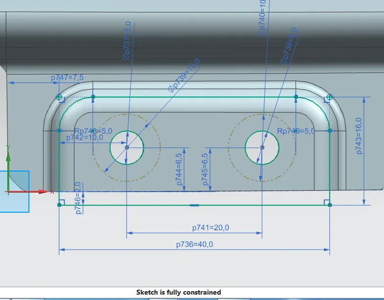
Fully Constrained Sketches with 5mm flat face around mounting holes
MANUFACTUIRNG FEASIBILTY
The final sheet designed is thickened to desired thickness and for feasible manufacturing conditions the steps followed are
- Relief along the corners
- Smooth Cut Section for linear tool movement
- Suitable Draft Angle for stamping process
- Considerable feature clearance from trim edge
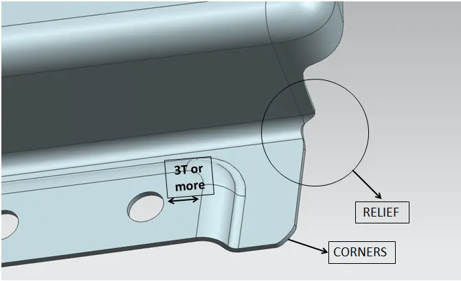
- Sharp corners are filleted and reliefs are provided to imporve the surface of the sheet and avoid stress concentration and Surface irregularities
- The feature holes are provided are ensured with minimum clearance for sheet metal processes to avoid forming near holes
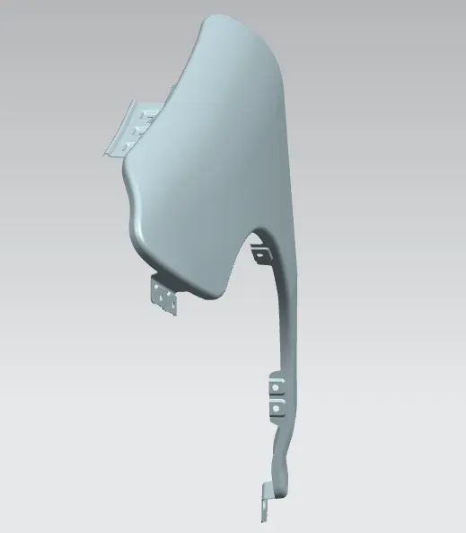
Shaded view of thickened Fender
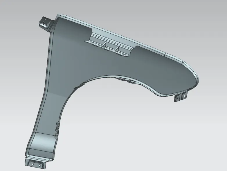
Fender Rear View
Conclusion
Thus Front Fender is developed in NX with Mounting Structures using proper design guidelines