Fender Design
Design of Car Front Fender Using NX CAD
Objective
This project aims to design a car front fender using Siemens NX CAD software, ensuring adherence to design standards and regulatory requirements.
Introduction
A fender is an essential component of a vehicle, designed to frame the wheel well and prevent debris like mud, rocks, and sand from being thrown by tires. This helps protect pedestrians and other vehicles from potential harm. The fender is also important for pedestrian safety, as it prevents stones and debris from being projected towards the pedestrians, known as anti-chipping. Additionally, the fender serves an aesthetic purpose by covering the engine compartment, hiding the engine bay from the top, and contributing to the overall vehicle's appearance.
Fenders are installed on both the front and rear sides of the vehicle, with distinct designs for front and rear fenders.
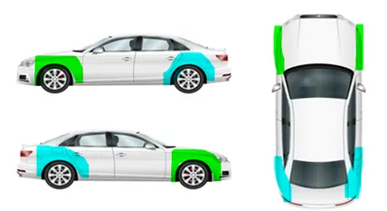
Types of Fenders

1. Full bumper type
The full bumper type fender was mostly used in old vehicles that had longer bonnets. This type of fender is designed to cover a larger portion of the wheel area, providing more coverage and protection. However, there will be a huge material waste, hence it increases the overall weight and cost of manufacturing. This is the reason it's less preferred.
2. Half Bumper type
In contrast, half bumpers and fenders offer better material efficiency. By increasing the length of the steel blank, which is used for the full bumper, even if it's possible to produce two half bumpers from a single sheet, significantly reducing material usage. Since every inch of steel counts in terms of cost and weight, this approach supports economical manufacturing. These fenders will allow the use of plastic components for the bumper sections, which further reduces steel consumption. As a result, overall weight decreases and leading to improved performance and fuel efficiency.
Material used for Fender
Fenders are usually made from materials like steel, aluminium, and thermoplastic olefin elastomers(TPO). The choice depends on factors such as vehicle type, weight requirements, and cost. While steel offers strength, aluminium and TPO are preferred for lightweight and fuel-efficient designs.
Design Considerations
Key parameters to consider during fender design include:
- Drip area clearance
- Mounting positions
- Wheel clearance angles
- Radius and Curvature (minimum of 2.5 mm on edges of fender)
- Material thickness (typically 0.75 mm)
Types of Mountings of Fender
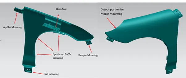
There are five primary mounting locations:
- Drip area
- Bumper Mounting
- Splash/ baffle Mounting
- Sill Mounting
- A-Pillar Mounting
Fender Drip Area
The drip area is a critical zone that connects the fender to the engine compartment. It must be designed carefully to provide proper mounting space. The cowl mounting, which holds the wiper motor and related parts, requires at least of 200mm of space.
Similarly, the headlamp housing needs a minimum of 150mm for secure placement. While there's no fixed length for the fender itself, these clearance requirements define the remaining space as the drip area, which must be strong enough to support the structure and allow proper joining.
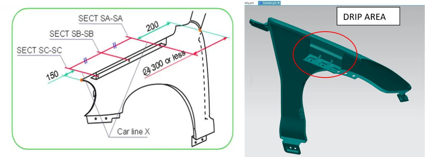
Design considerations for the drip area
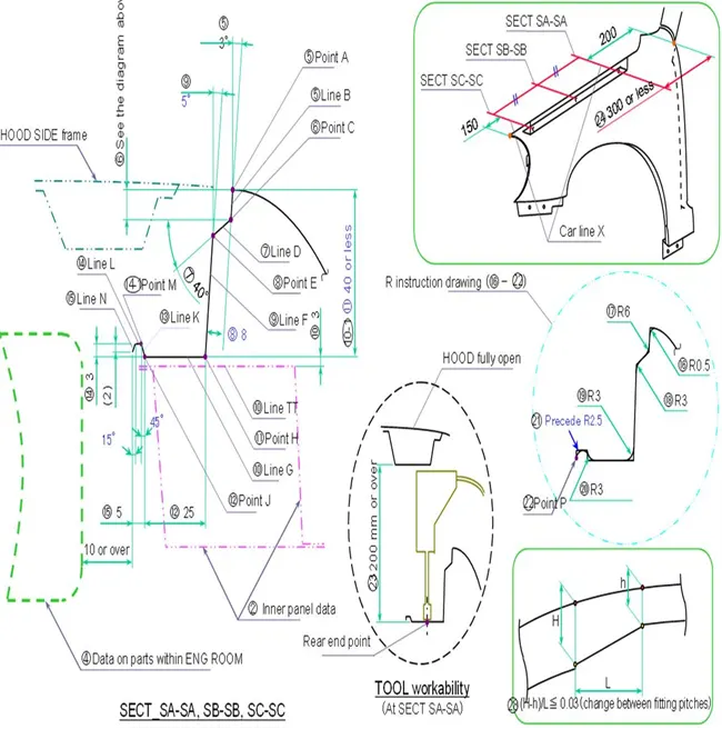
3° Draft Angle
A minimum draft angle of 3° is required in fender design to allow removal of the part from the tool without damaging the surface. This angle is considered standard in the industry. However, this angle may be increased depending on the aesthetic requirements to achieve tighter or move refined surfaces.
7mm Flange (Visual Gap Cover)
When viewed from the top, a visible gap can appear between the hood and the fender, showing parts of the engine compartment. To block this view and maintain a clean look, a 7mm flange is added. This prevents visibility into the engine bay when the hood is open and ensures a neater appearence, especially when observed from outside or during servicing.
37 mm clearance for Tool Access
A 37 mm space (typically between 35-40 mm) is maintained to allow tool access and proper functioning during hood installation. When the hood is open, this space ensures the fender can be securely mounted with weld nuts on the engine compartment. This clearance helps during the alignment of parts and prevents interference with tools during assembly.
The minimum flange length on the fender is designed to align properly with the engine compartment area. To strengthen this edge, an emboss or rib is added. A plan flat sheet may bend or deform easily, so embossing helps maintain rigidity. A 10 mm gap must be maintained between the emboss and
the engine for safety and clearance.
Flange Depth (40 mm)
The flange depth is typically around 40 mm, which is considered optimal for drawability manufacturing ease . If the depth exceeds this such as going to 60 mm it may cause spring-back, where the part slightly shifts position after forming due to internal stress. If the flange length cannot be adjusted properly,
adding a rib helps in maintaining strength and shape.
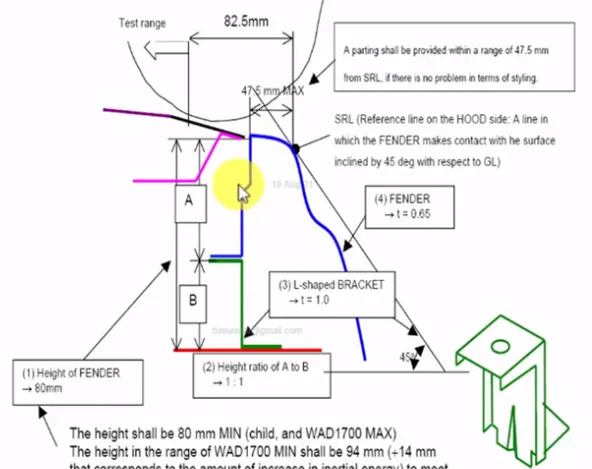
L-Shaped Bracket
An L-shaped bracket, usually placed at a 45 angle, is used to connect the fender and the hood area. The maximum allowable length for this bracket is 47.5 mm going beyond this can interfere with vehicle styling and surface flow. In terms of height, the fender should be 80 mm to meet standards, especially for children. For vehicles requiring WAD 1700 mm pedestrian impact compliance, the height must be increased to 94 mm to ensure protection for adults as well. These dimensions are crucial for maintaining both safety and design quality in fender layout.
Wheel Arch
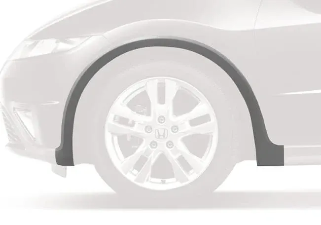
In fender design, special attention must be given to the wheel arch and drip area once the skin data of the fender is received. The wheel arch surrounds the rotating tire and plays a key role in both safety and aesthetics.
If the wheel extends outside the fender when viewed from the front, it can result in stone chipping, potentially harming pedestrians or damaging the vehicle body. To avoid this, the wheel should always remain within the fender boundary, ensuring better protection and visual appeal.
Standard Clearance Specifications
Different countries define minimum clearance standards between the wheel and the inner surface of the fender to ensure safety and meet legal norms. These clearances are checked at specific angular positions around the wheel arch.
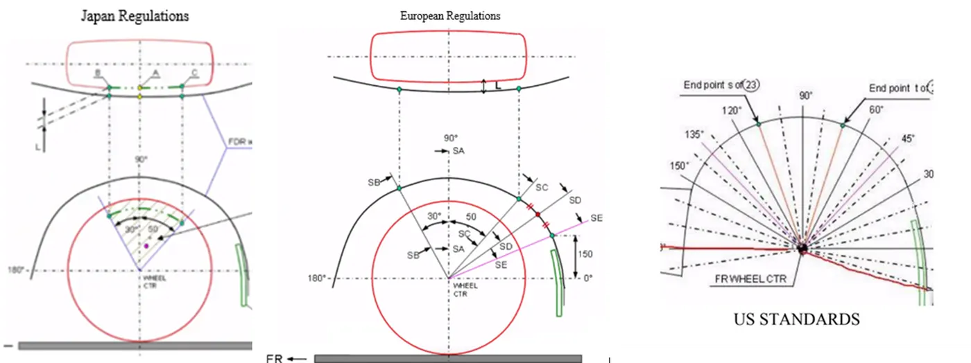
1) Japan Regulations
In Japan, the wheel arch must maintain a minimum clearance of 5 mm at key points typically marked as positions. A,B and C. These are checked by drawing lines at 30 and 50 angles from the front of the wheel center.
* If the clearance L < 5 mm, the fender design must be modified.
* Often, the styling team needs to adjust the fender curvature to meet these requirements.
These guidelines are issued by the Automotive Research Authority and enforced by the Road Transportation Department.
2) European Regulations
According to European safety standards, the fender must maintain a minimum clearance of 10mm at several specific points along the wheel arch. These positions are :
- At 30°, 50°, A point (front most contact point), D point(midway between 50°and 150°), E point(located at 150° )
To meet the regulations across all markets, it is common practice to follow the strictest clearance requirement, which in the case is 10mm. This simplifies manufacturing and ensures global compliance without requiring design changes for different regions.
3) US STANDARDS
In the united states, the required wheel clearance is checked over a broader range- from -100° to 100° measured from the centre of the wheel. At every point within this range, the minimum clearence should be greater than 5mm to ensure safety and prevent debris thrown outside the wheel well.
Key Design Notes
1. Many manufacturers prefer to follow the European clearance of 10mm, despite the US allowing slightly smaller clearances. By designing a single fender that meets international regulations, they can use the same fender in both markets. This approach saves on design, tooling, and production costs while ensuring global compliance.
2. While components like the body sill, bumper, and other mountings are designed based on their individual requirements, the drip area and wheel arch are directly influenced by the fender design.
3. A minimum corner radius of 2.5mm should be maintained on the fender edges. This improves the visual appearance of the vehicle and enhances pedestrian safety by reducing sharp edges.
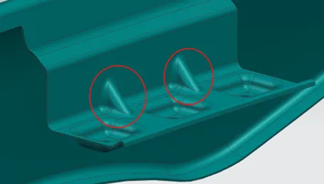
4. Dart
A dart is a small cut or natch added in the sheet metal of the fender to reduce stress and control the flow of material during forming. It helps avoid wrinkles or deformation in curved or bent areas. Darts also improve the strength and shape of the part without increasing material thickness.
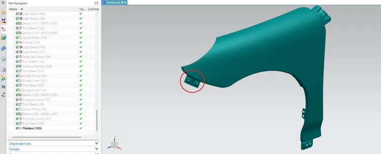
Bumper Mounting
The bumper mounting point on the fender provides a secure connection between the fender and the front bumper. Mounting holes are included in this area for fastening components. The bumper mounting point on the fender is essential for creating a secure connection between the fender and the front bumper. This area features mounting holes designed for easily fastening components, ensuring stability and preventing misalignment while the vehicle is in motion. Overall, it enhances both the vehicle's appearance and safety.
Splash/ baffle mounting
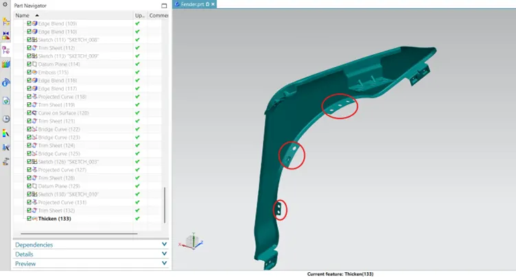
This mounting is found near the wheel arch and is used to fix splash guards or baffles. These parts help block mud, water, and small stones from entering the engine area. They also reduce noise. Extra holes or flanges are added to the fender for mounting, and their use depends on the vehicle type and region. The use of baffles depends on the vehicle type and region- common in diesel vehicles in India and used for all types in other countries.
Sill Mounting
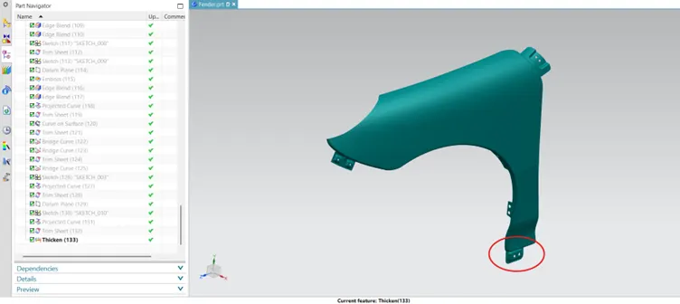
Sill mounting is located at the bottom end of the fender, where it connects to the vehicle's body sill. It helps hold the fender firmly in place and supports the overall structure. This mounting also helps reduce vibrations and noise while driving. Proper fasteners are used here to ensure a strong and stable connection.
A-Pillar Mounting
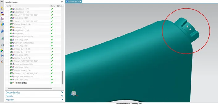
A- Pillar mounting connects the fender to the A- pillar of the car, which is the vertical support between the front windshield and the door. This mounting adds strength to the fender stays properly aligned with the door and hood area.
Fender Design
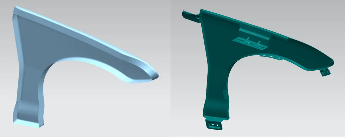
SKIN DATA TO FINAL PRODUCT
Conclusion
Finally, the design of the front fender was completed using NX-CAD software by following the master section. Mounting flanges were developed in key areas such as the drip area, sill mount, A- Pillar and bumper as per given design requirements.
DRIVE LINK:
https://drive.google.com/file/d/1d6ZxOBCxpF9cWs9XFVJO5Ki1TDN3TM-t/view?usp=sharing