Fender Design
Objective:
The aim of these project is to design fender and the main design requirements for Drip, Bumper, A pillar and Sill mounting areas.
Fender
Fender is a front outer side member of a car which covers the wheel side. Fender purpose is to prevent sand, mud, rocks, liquids and other particles. or
Fender is a closure component, closing the engine compartment and other compartments. The major role of the fender is to avoid the chipping inside the engine compartment. During the motion the wheel picks a sand mud and small stone particles and throws it inside the car and these fenders will be helpful in preventing them by hitting inside the engine compartment and car body. These fenders will have a plastic part which lies on wheel arch area. The fender plays a major role to avoid problems for pedestrian also.Fender are typically rigid and can be damaged by contact with the road surface. It is often also called as Mudguard.
Types of fender:
- Full Bumper Type.
- Half Bumper Type.
Full Bumper type:
It is not used now a days because they requires bigger size blank to produce the part and the large scrap is also produced.
Half Bumper Type:
Half bumper types are used in present and future also because the blank size is less and the wastage or scrap is less comparing to full bumper type fenders.
Uses of car Fenders:
- Car Fender limit the exposure of your car's body and engine to external elements that are harmful.
- Fender flares are attached to ensure that both the body and engine have minimal contact with corrosive elements
- Car Fenders provides safety to the driver and the passengers at the time of accidents or collisions. They are manufactured in a way to provide bend during front and side collisions.
- Car Fenders are designed to avoid wind resistance and make your car more aerodynamic.
- Car Fender enhance the overall look of your cars. Fender flares are available in distinctive designs in the market. Mostly you find universal Fender flares, but you can get customized cars Fenders to fit your car wheels.
Areas to be considered while designing a fender:
- Drip area
- Bumper mounting area
- Sill mounting area
- Body mounting area
The drip area is the connection of the fender with the engine compartment.
DRIP AREA:
It is the area through which the Fender is attached to engine housing through fasteners. There shold be some consideration followed to design the drip area, from back side of the fender there should be 200mm clearence for cowl mounting area and from the front there should be 150mm clearence for the head lamp housing unit.
Considering the above design constrains we have to design the drip area. Embosses are provided to increase strength, corners of the flanges are smoothen to ease of the production. Uniform wall thickness of 0.75mm.
- Design Consideration for drip area are150mm distance from front end of the fender and the gap is filled with headlamp200mm distance from rear end of the fender and the gap is filled with wiper motor assembly.
- Initially 3-degree angle and 9mm length is given while creating a drip area because the engine component should not be visible from outside.
- The depth of the drift should be between 40 to 60mm. If the depth exceeds from 60mm then forming is not feasible due to spring back and wrinkles.Embosses and ribs are given to drip area to give strength. Embosses dimensions are depth 3.5mm and 15 degree of angle for all three embosses.
Procedure:
- Creating the sections:
- After Opening the File, Check the model and create the mount area layouts.
- Use parallel curve option to offset the line to 5mm and split option cut the class A to create a space for the mountings.
- Now, join the split surface excluding the top surface.
- Creating the Mount part:
- To create the mount regions, use the sweep option near the space created for the mountings.
- After the sweep is done as per the design model given, join the surface created.
- Creating the embosses and relief:
- After the mounts are created, we need to create embosses and holes are to be given.
- To create emboss, create a sketch with the required shape. Project the sketch onto the mounting area but before that extract the surface.
- Now, split the surface to create a hole near the projected area to create an emboss.
- Use the sweep command near the cut section. Now, offset the extracted surface.
- Trim the surfaces together and create a relief hole which is given to such that the screw is fitted into that hole.
- For the Drip Mount part, follow the details given and design the product.
- To create beaks, create the surface in a way that is angular and then trim the surfaces together.
- Giving the Fillets:
- Once the surface is trimmed, give the fillets near embosses and beads.
- Use the Extrude command followed by the edge fillet to create the sharp edges to the curved parts near the mountings.
- Creating the Solid:
- After the Surface is created, go to the part workbench and define the part body.
- Use the thick surface option to create the solid with a thickness of 1mm.
A PILLAR AREA:
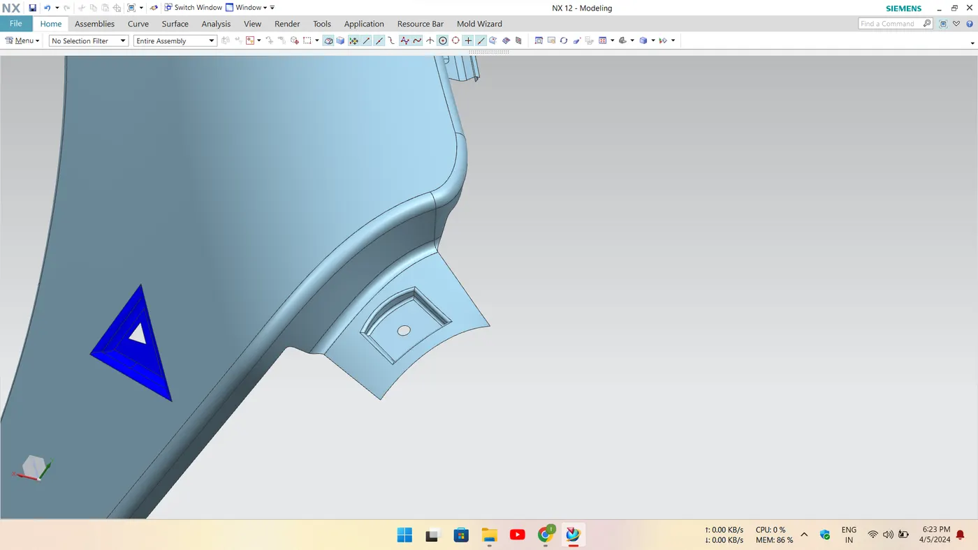
A Piller is on the cars either side of the front windshield which is the reason the windshield in the place.
It is Mounted on the A Pillar by means of fasteners and these are covered by outer side view mirrors.
Here, the proper embossing are provided along with holes for fasteners.
- Law extension dimensions are 42mm length and 90 degree of angle.Offsetting the law extension face 5mm.Creating a sketch and law extension feature is used 6mm length and 95 degree of angle.Trim sheet to create a hole of 5mm diameter.Edge blend and face blend are 2mm.
SIL MOUNT AREA:
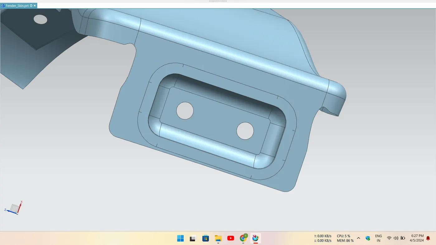
The Sill Mounting area is in the bottom of the fender.
- It is mostely gets connected with the door region of the car.
- Here, proper embossing and holes for the fasteners are provided.
- The ribs are provided to improve the strength.
- Extend sheet to 15mm to make the sheet length 30mm.Giving relief by manual like creating a sketch and trim the sheet both sides.Emboss dimensions are depth 3.5mm and 15 degree of angle.Edge blend is 3mm.Trim sheet is used to create a 6mm hole on sheet.
BUMPER MOUNTING AREA:
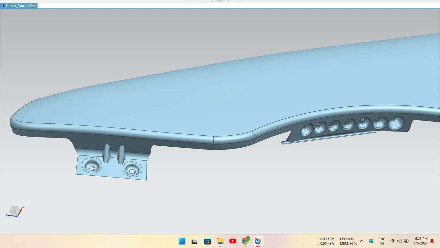
In this Mounting, the Fender connects with the bumper.
The Bumper Mounting region must be rigid in order to withstand the force acting upon it during collision. So, the Mounting space can be larger.
- Law extension length 20mm and 75 degree of angle. Skew to join the two surfaces.Dart angle 45 degrees, depth 4mm and radius 3.75mm. Create two darts in existing spaces as shown in figure 7. Trim sheet is used to create a hole of dia 5mm.For skew use 3mm edge blend and for dart and embosses 2mm edge blend.
BAFFLE AREA:
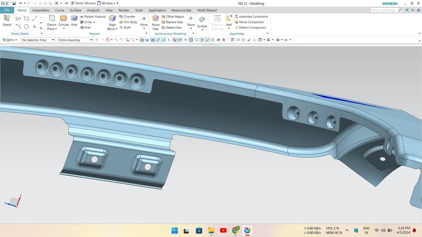
Creating holes for baffles.
Trim sheet feature is used to create holes of 5mm.
SOME VIEWS:
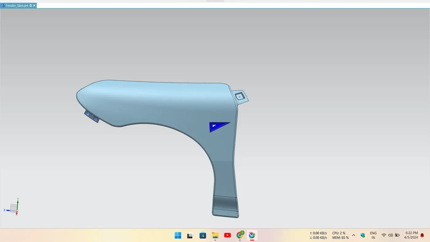
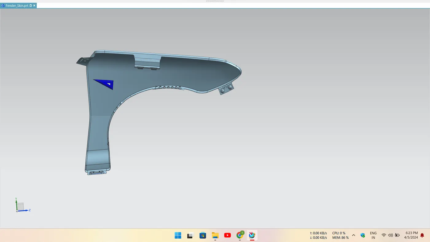
Conclusion:
Developed the Drip, Bumper, Sill, A pillar and Baffle mounting areas by design requirements of the fender design.
EXTRAS: I have Created the Indicator area which is Blue in colour which you can find in the screen shot.
files of the fender nx file is attached below