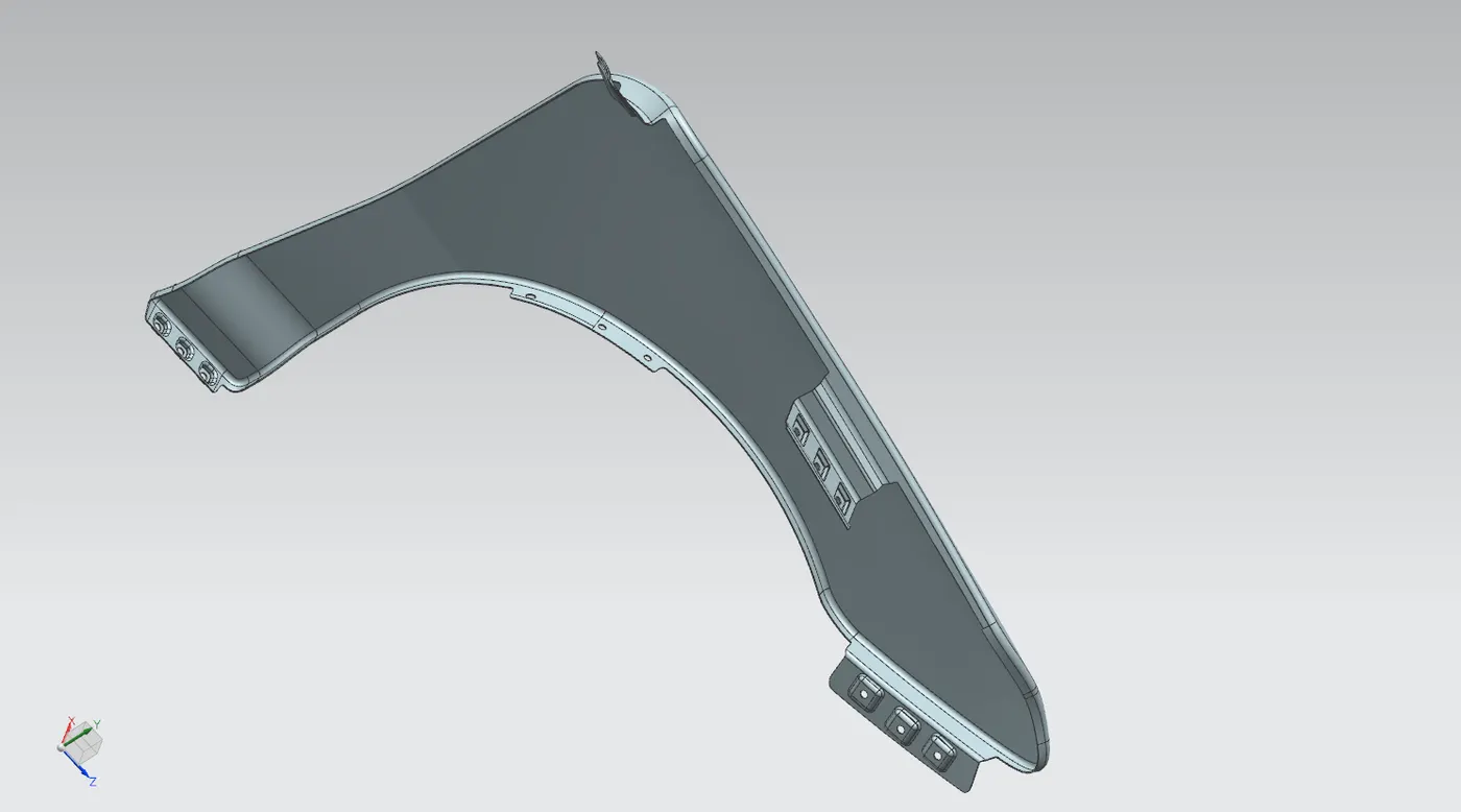
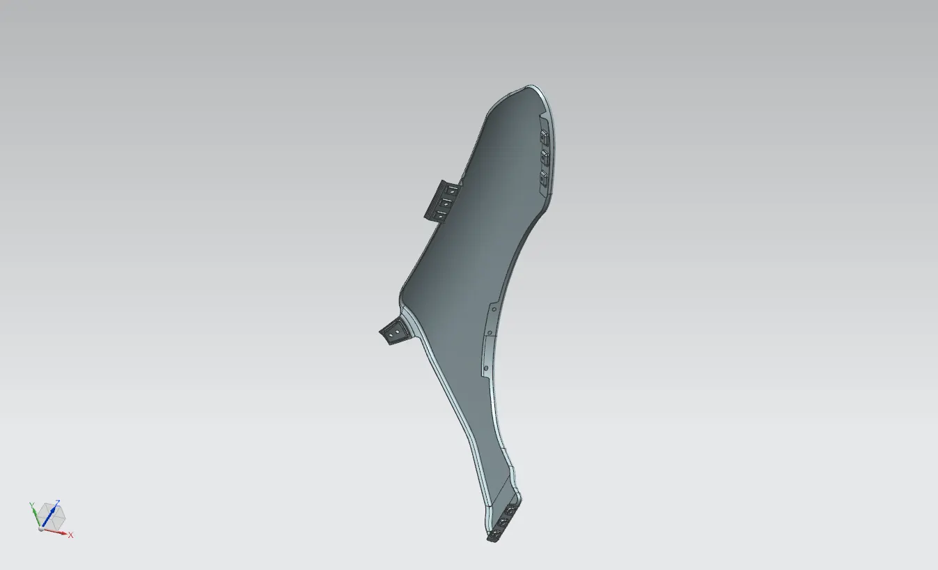
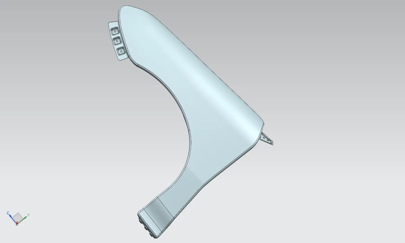
Fender Design
Fender Design
Objective:
To design a body in white front fender of a car with its mounting using the information provided by the styling team.
Introduction:
Fender:
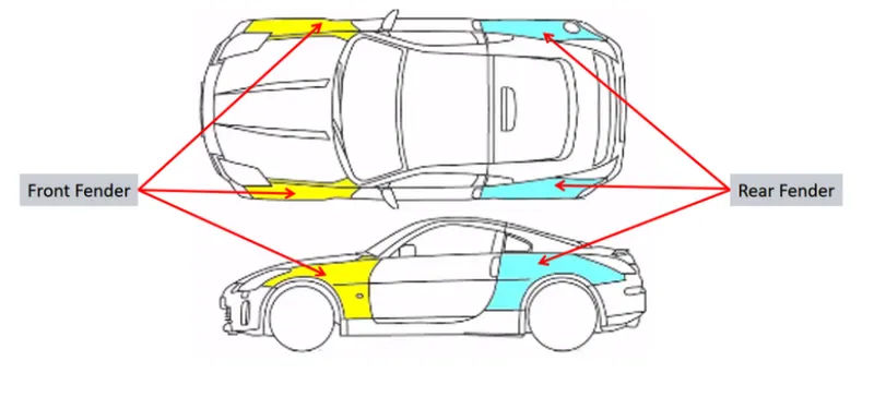
Fender is a body part of an automobile vehicle whose function is to cover or shield the wheel above the ground. Its primary function is to prevent mud, small rocks, sand, liquid and other small elements present on the road being thrown in the air by the rotating motion of the tyre. When the vehicle is in motion, the tyre pick up the small elements (solid & liquid) present on the road and due to the centrifugal action these elements got thrown outside as well as inside the car and engine compartment. This activity might cause some hazards to the pedestrians and to the vehicle itself and other vehicles around. The fender eliminates this activity by a considerable amount and these striking particles by the tyre get accumulated on the baffle mounted underneath the fender. The fender also hides the BIW components present inside and the ugly regions of the vehicle.
Types of Fenders :
1. Full fender type
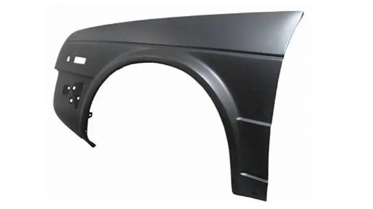
Full fender type is traditional type fender where more material consumption is observed. This type of fender is used in old design of automobiles where it increases the overall weight and thus reduces the performance of car.
2. Half fender types
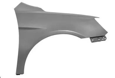
Half fender type is modern design where less material consumption is observed so productivity increases by reducing size of blank and thus providing more performance. The maintenance also relatively low compared to full bumper type.
Manufacturing process:
Deep Drawing:
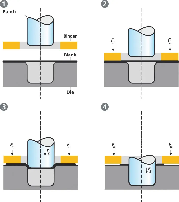
In the deep drawing process, the sheet metal is radially drawn into the die cavity by the mechanical action of a punch. In this process the work piece is put onto the die and the blank-holder is then introduced on the top of the work piece, which is not deformed by the punch.
Types Of Mountings :
1. A Pillar Mounting
2. Bumper Mounting
3. Drip Area mounting
4. Baffle Mounting
5. Sill Mounting
Design Construction:
Skin data and master sketch:
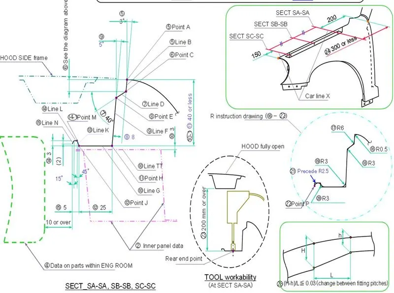
1. Designing the A Pillar and its Mounting:
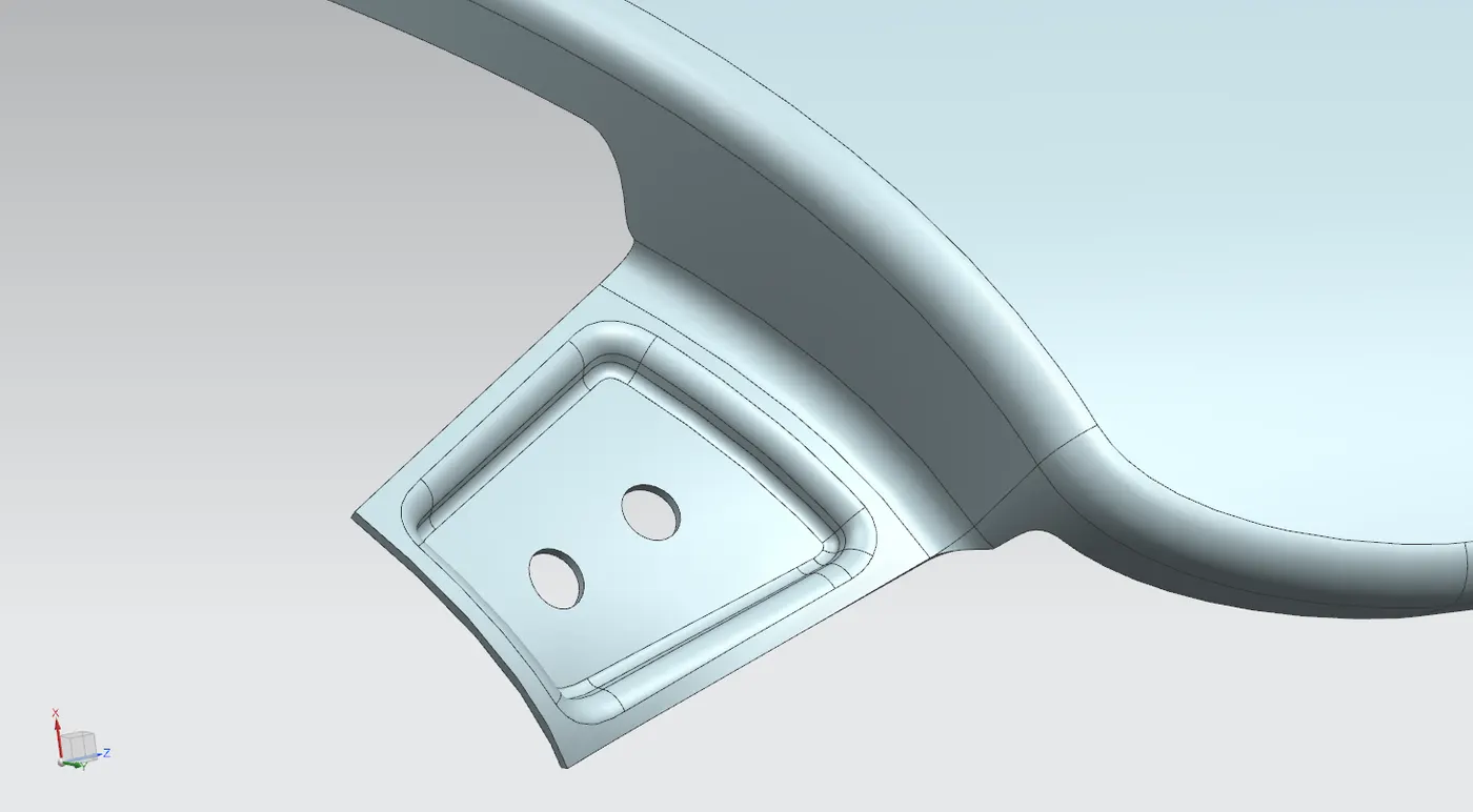
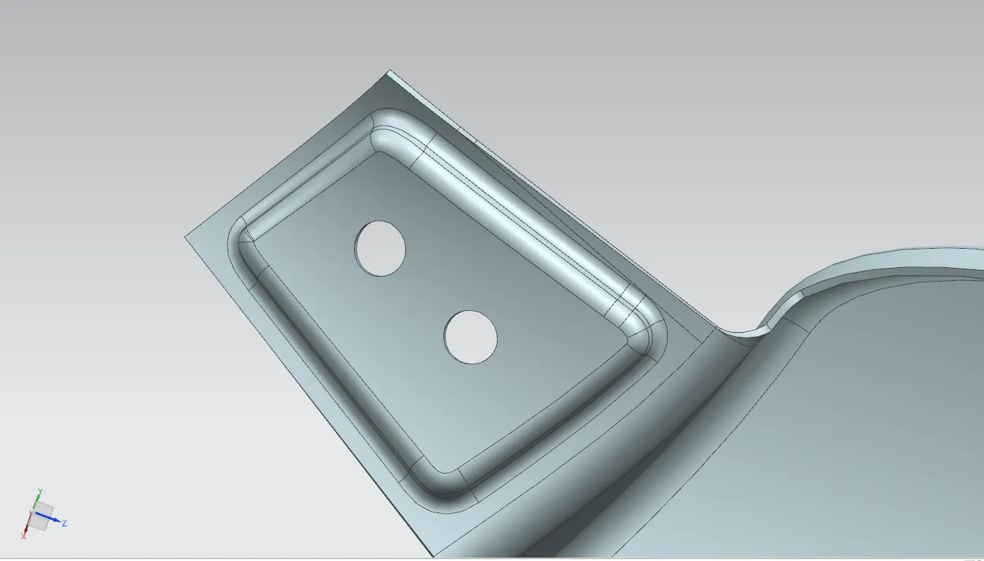
The process begins with extracting the skin data provided by the styling team. Next, the outer edge of the fender is offset inwards to a specified length. Utilizing the curve on surface command, the unwanted portions are trimmed out using a trim sheet.
To extend the A-pillar and trim its sides to achieve a flat edge, the law extension is applied. Subsequently, a datum plane is created to establish a flat emboss for mounting the fender with the A-pillar. The necessary sketch is drawn on the datum plane and projected onto the surface.
To create fastener holes with approximately a 5mm gap around them, the trim surface command is employed. Finally, the required blends are incorporated using both face blend and edge blend techniques.
2. Design the Bumper and its Mounting:
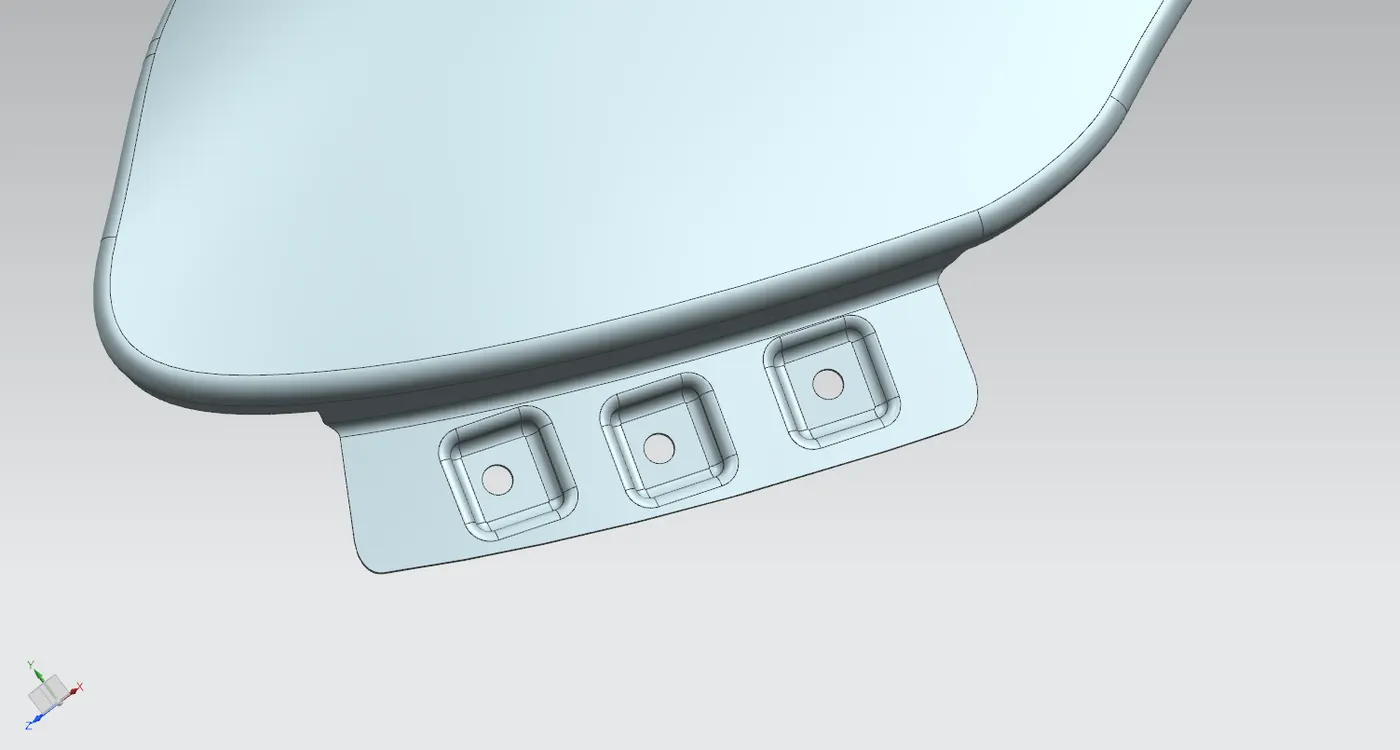
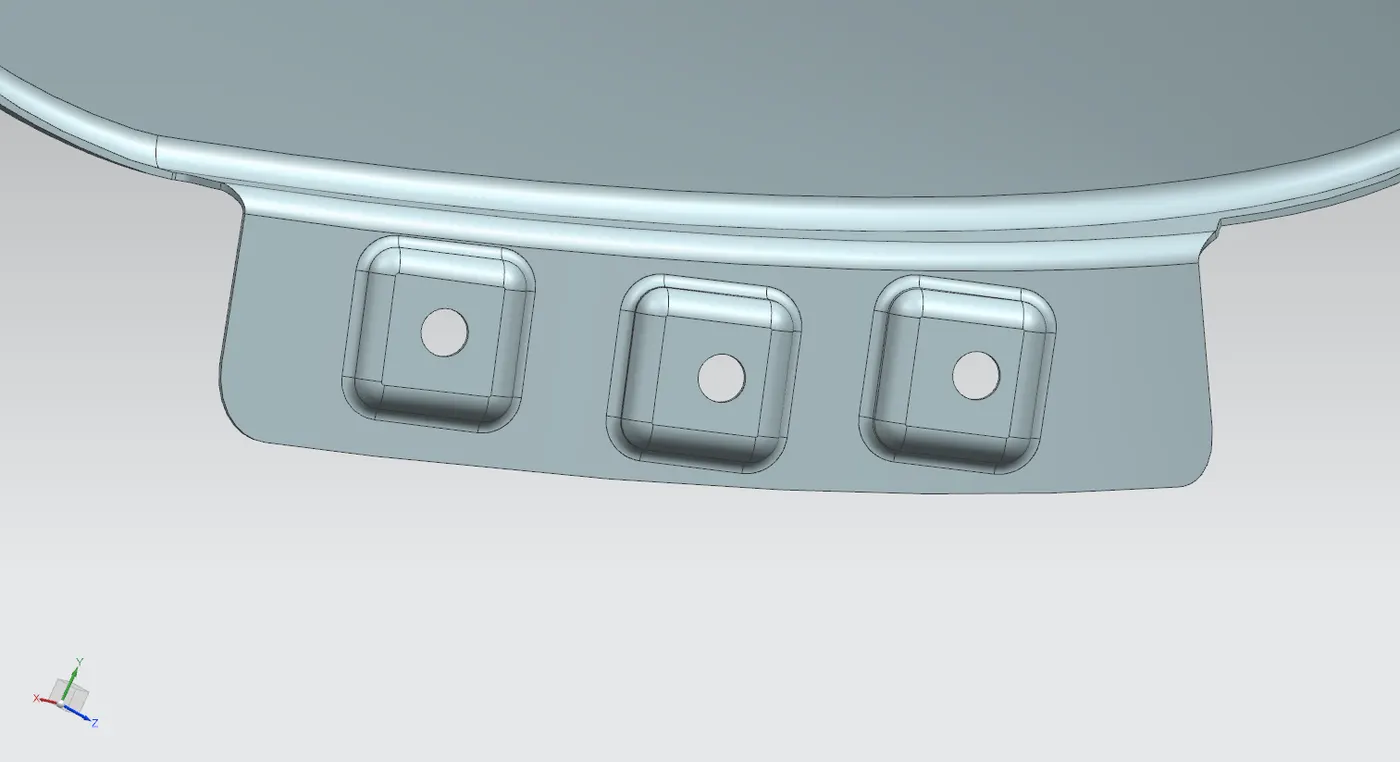
The unnecessary sections were removed utilizing the curve on surface and trim surface commands. Subsequently, to establish a flat surface emboss, a datum plane was generated. The necessary sketch drawn on the datum plane was projected onto the surface, and the required embossments were created.
After creating the embossments, the holes were trimmed using a trim sheet. Each emboss was crafted with a draft to meet manufacturing specifications. Lastly, the required blends were applied to complete the process.
3. Design the Baffle and its Mountings:
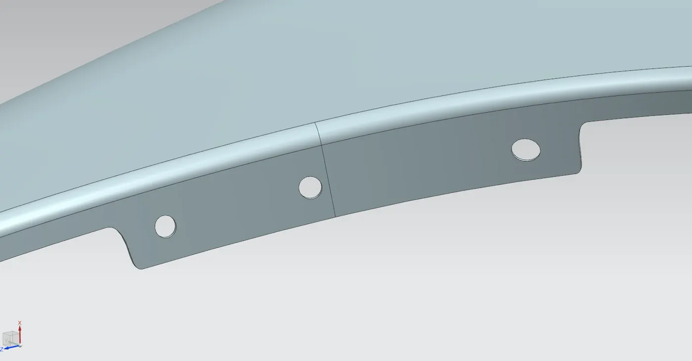
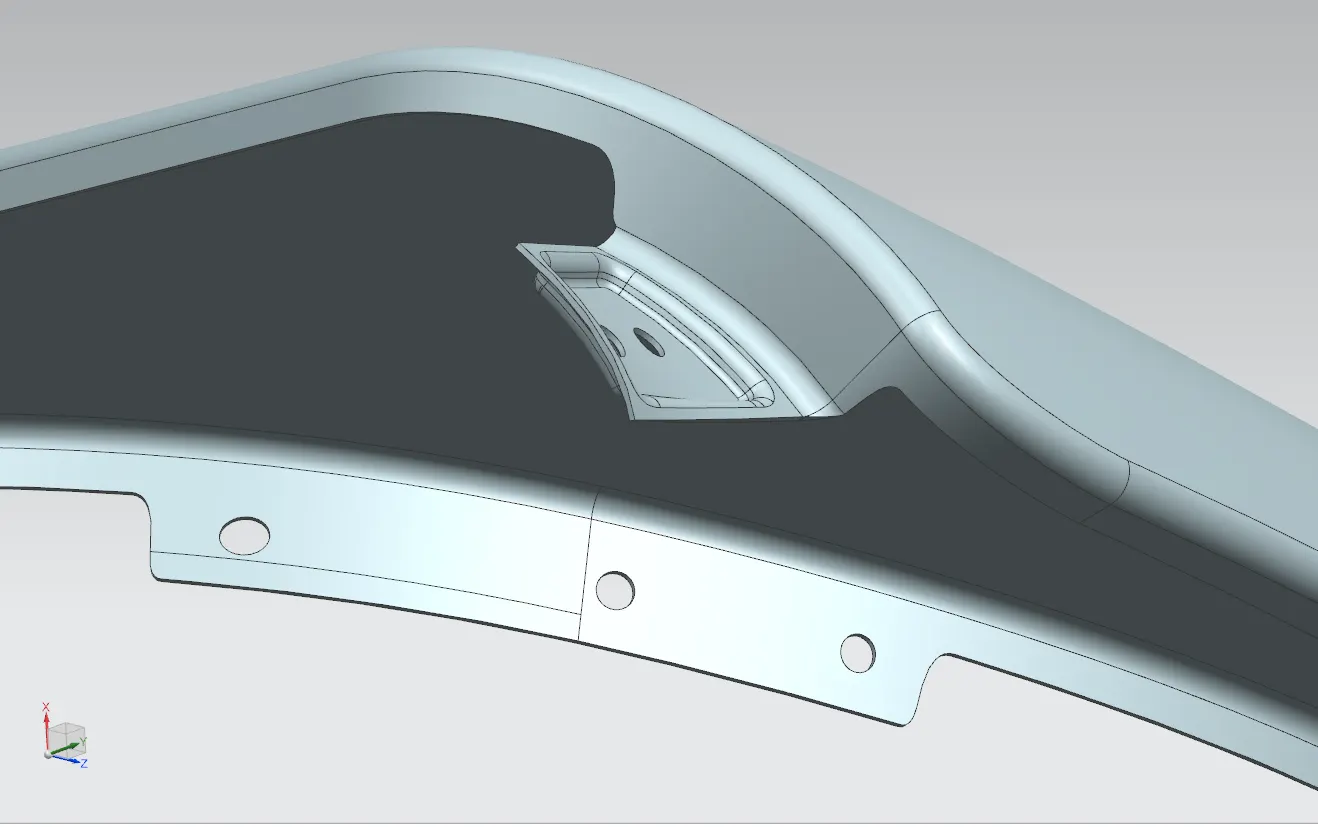
The baffle mounting was designed to accommodate a splash mount, aiding in shielding the engine compartment from debris during driving. To create it, three mounting areas with necessary holes for fasteners were established.
To create the holes, a datum plane was generated for all three mountings and projected onto the surface. By selecting the required vector and deselecting the option to project on both sides, the holes were created.
4. Design the Drip Area and its Mountings:
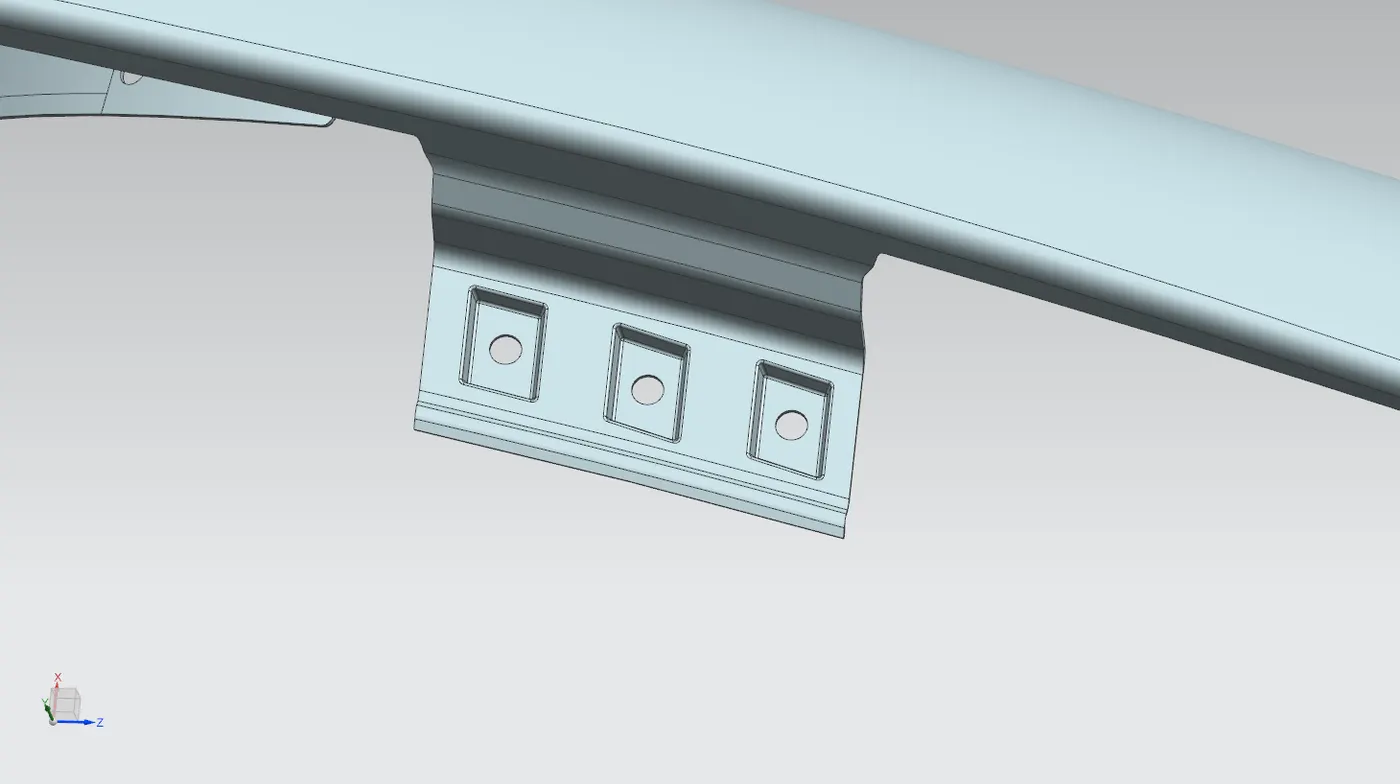
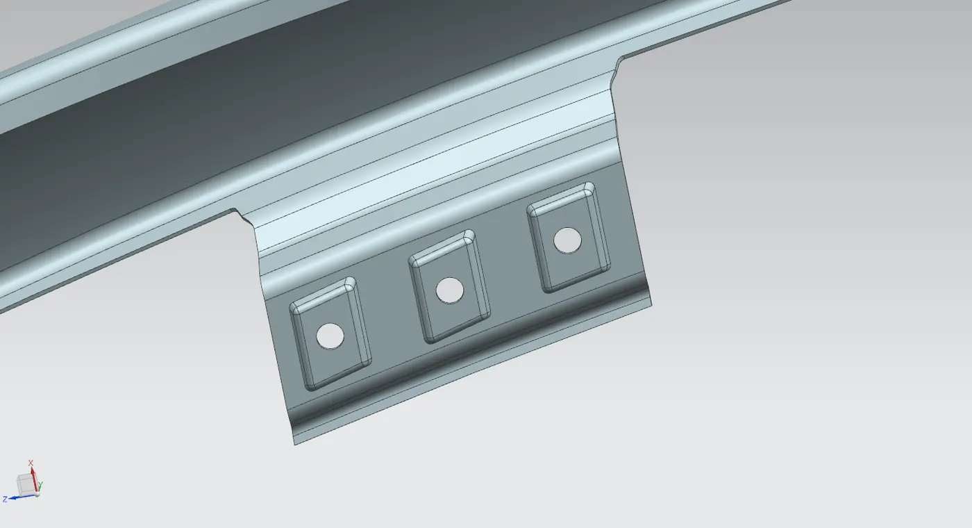
Using the information provided in the master section, we created the drip mounting. To ensure the drip mounting doesn't interfere with the headlamp mountings, it needs to be at least 150 mm away from the front edge. Also, it should be 200 mm away from the back edge to avoid issues with engine cables.
To create the drip area at the specified distance, we made two planes and used the intersection curve to create the curve on the surface. Then, we trimmed out the unwanted parts. The design is crucial in preventing people from seeing inside the car through the gap between the hood and fender, so the drip area was made at a particular angle as instructed by the master section, and the necessary embossments were created.
After making the law extension as directed by the master section, we created the required embossments. To create the embossments, we made a datum plane, drew a sketch on it, projected it, and applied the emboss feature. For the fastener holes, we used the trim sheet options. Additionally, we created blends to enhance the fender's appearance.
Since the drip area is long and lacks support, it increases NVH (noise, vibration, and harshness) while driving. To minimize the NVH effect, the drip area needs to be strengthened.
5. Design the Sill and its Mountings:
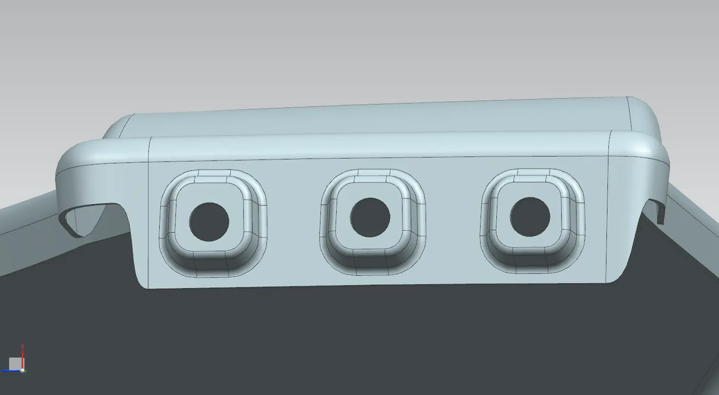
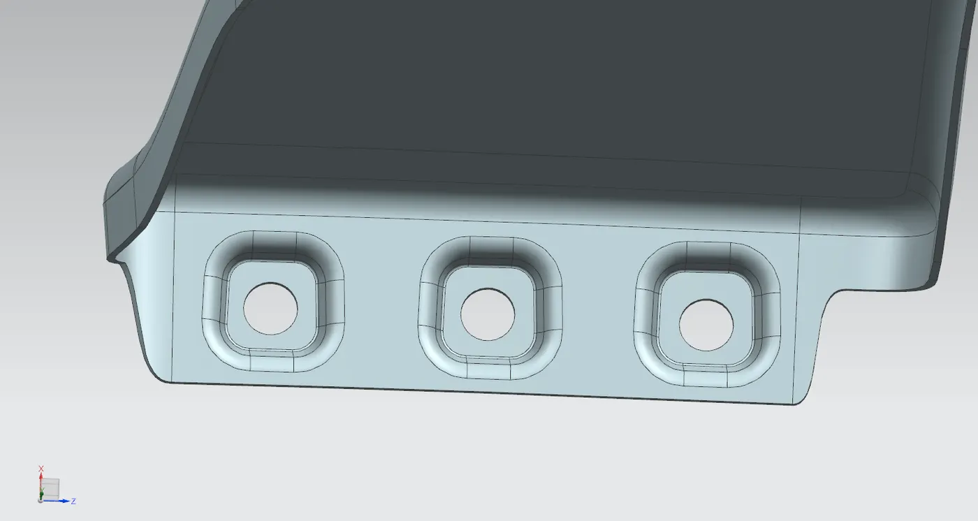
To craft the sill mounting, we first trimmed away any excess portions. Then, we established a datum and drew the necessary sketch, which was then projected onto the surface. Embossments were generated and the edges were blended together seamlessly. Fastener holes were fashioned using the trim surface feature.
Different Views of Fender: