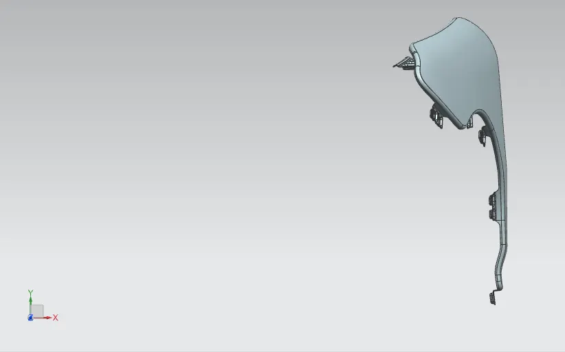
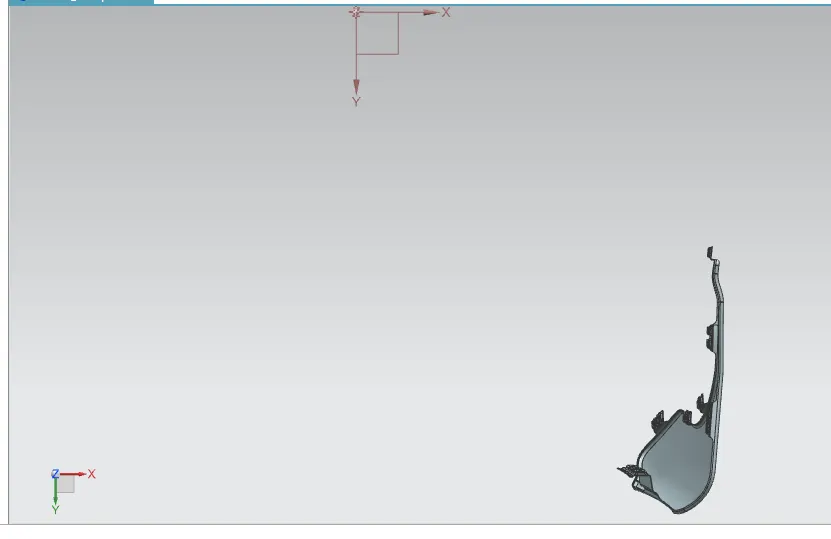
Fender Design
Project : 2 : Fender Design
Aim: Design the Fender Mounts as per standard and master data.
What is Fender:
Fender is a US Engilish tearm for the part of Automobile Vechile BodyThat Farmes while well the fender under side .
Its primary purpose is to prevent sand ,mud,rocks,liquids and other road spray from being thrown into the air by the rotating tire.
When vehicle is moving tires pick up the stones and othres hurt them in all directions. Fenders are basically present to prevent any lnjuries to pederstrains and contain the motion of those particals.
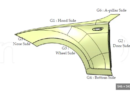
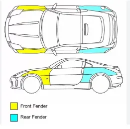
The verious requirements are have in fender design,they are,
1.Design Requirement.
2.Functional Requirements.
3.Important Regulations.
4.Drip Area.
5.Wheel Arch.
6.Baffle and ORVM Mount Area.
7.Frontal Crash Regulation and Requirement.
8.GAP and Flushness Requirement.
Plastic part are there in fender,they are located in fender arch area.The bigger part is basically helpfull to preventing the Engine compartment.
This Fender is always play the major role for prevent injury the pederstrains.whatever comodety to bedesign we likr to think of the pederstrain whose been attack to this.
Then Type types of fender we have ,they are,
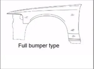
1. Full Bunper Type.
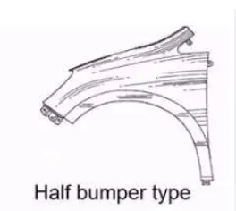
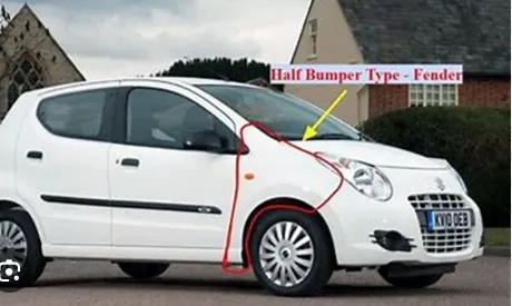
2.Half Bumper type.
Recent times we have used half bumper type fender only.Becaus when ever we create full Bumper fender the creation or making process are so big.and lot of material wastages are happening.
But the half Bumper type is we have high possibility to reduce the scrap and create two fender at same time for slightly incress the Blank Size. This what is called scrap management.Because every inch of sheet metal are high cost.so i will be given the styling and choosing half bumper type .Because i am reducing the material usage.
Fender Mounting Points:
1.Body
2.A- piller
3.Sill
4.Cowl
5.Drip
But Major important mounting unit of fender is Drip Mounting.Its is connection of the fender with the engine compartment.
Fender Manufacturing Process:
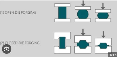
The manufacturing process includes the following steps that firstly, unfolding and shearing are carried out on a plate, wherein a proper cold roll specification is selected at first, a cold roll is unfolded, and then the unfolded cold roll is sheared to an iron plate of the corresponding size according to production.Die Forging method are use in the Fender manufacturing.
Master Data or Mastic Data:
Master data or mastic data is Define the part or product is how to design as per standard and requirement of current setution.That is call Mastic data.Mastic data of Drip mount is,
1.Fender rear end to Drip Distance is min - 200mm
2.Fender Front end to Drip Distance is min - 150mm
3.Remining are of fender drio is length of drip mount .
4.Drip depth shall be uniformA=B=C.
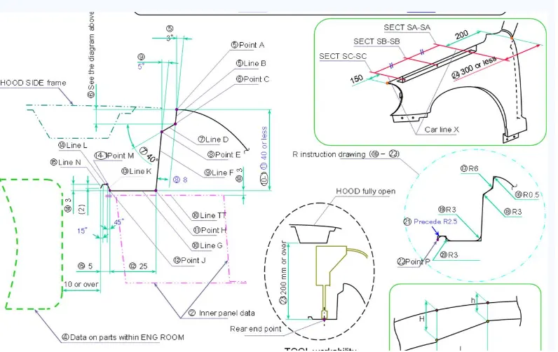
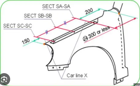
If unavoidably varioues if shall be eaither A>B>C or A<B<C
When the Drip Surface is stamped 3 deg must be secured for spring back the length of drip is more then 60mm they are have Spring back effect.so must be reduce the length or 45 to 60mm then only we have avoid the spring back effect.
Fender Drip Area Pedrstrain Safty:
1.The hight shall be 80mm Min (Child and WAD 1700 Max)
2.The hight in the range of WAD 1700 Min Shall be 94mm(+14mm that corresponds to the amount of incress in inetial energy) to meet adult impact requirement.
3.SRL Reference line on the Hood Side.A line in which the fender makes contact with he surface unclined by45 deg with respect to GL.
Wheel arch area:
Wheel arch is having standing some specific specification,
The various styling data are having in the wheel arch area in around the global.
They are ,
1. Japan Requirement,
2. US Requirement,
2. European Requirement,
Japan Requirement:
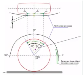
1.Measure clearence L of tire,Hub,Cap& Fender in three different Position with in area k and produce clearence check chart to validate.
2.Clearence must be greater than 5mm in all the three positions.Wheel Guart regmt the value of a shall be more than 5mm at a line 30deg forward and 50 deg rearward from the central Vertical axis of axis of wheel.
US Regulation Requirement:
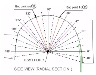
1.Make Clearence check detail on all position from -100 deg to +100deg & make the clearence check table.
2.All values should be greater than 5mm to satisfy the regulations.the value.The value of 'a' shall be more than 5mm at a line 30deg forward and 50 deg rearward from the central vertical axis of wheel .
European Regulation Requirement:
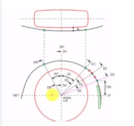
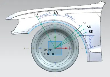
1.Measure CL at sections SA-SA,SB-SB,SC-SC,SD-SD,SE-SE and CL check to validate.
2.At all five sections the CL L value should be greater than 10mm to satisfy the european regulations.
3.Wheel guard regmt: the value of 'a' shall be more then 5mm at a line 30deg forward and 50deg rearward from the central vertical axis of axis.
Drip Area mounting:
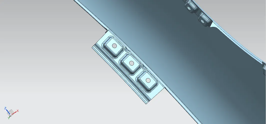
1.Open the fender skin drawing and create the initial frame for all mounting areas.
Select the offset curve command and click the boundary of fender and offset value 13.7mm then again create the offset and select boundary curve and say ok.
2.Now we want to make curve of the surface on the fender skin ,the drip mounting frame is Fender rear end to Drip Distance is min - 200mm, Fender Front end to Drip Distance is min - 150mm,Remining are of fender drio is length of drip mount .,Drip depth shall be uniform A=B=C. so we have to select the surface curve option and make curve on mounting areas.after create the mounting trim the unwanted surface by using tream sheet command.
3. Then we have select law extension command by using for Drip mounting frame creation as per mastic data .select the law extension command and pick the curve for initial frame and select the face of initial frame mention the value of length = 8mm and angle = 130deg and click ok.next create the 2nd frame length =25mm, angle = 125deg ,3rd frame length = 25mm angle = 100 deg ,4th frame length = 3mm angle = -135 deg ,5th frame length = 5mm angle = -135deg ,6th frame length = 2mm angle = 75 deg .Now we have creat the datum plane in face of drip mounting .this area is tough with Engine compartment.
4.Now we have create the sketch and embosed the sketch then trim the mounting Holes then create dart also because the mounting frame is so long.thats why we have create the drat its like a stiffner also in sheet metal surface . we have a make the face blend and edge blend in all sharp corners.
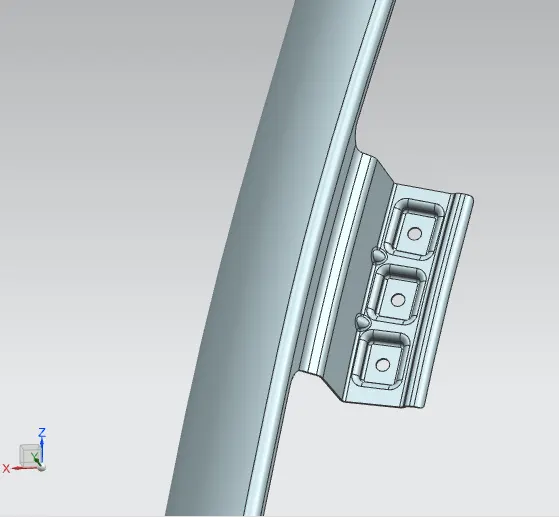
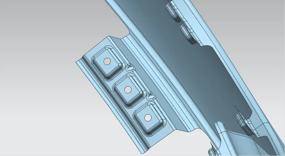
Bumper Mounting:
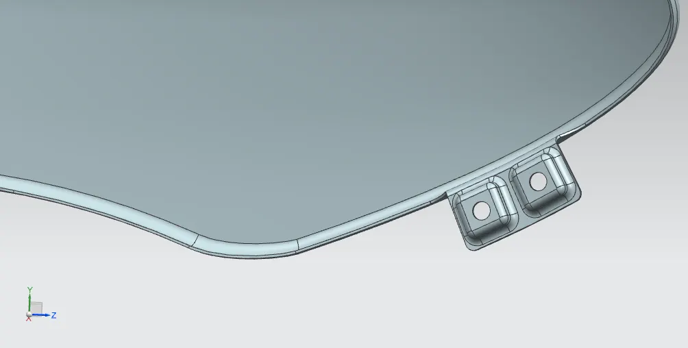
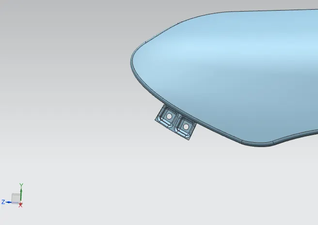
1.Now select law extension command by using for Drip mounting frame creation as per mastic data .select the law extension command and pick the curve for initial frame and select the face of initial frame mention the value of length = 20mm and angle = 90deg and click ok.Now we have creat the datum plane in face of drip mounting .this area is tough with front Bumper (Boonet).
2. And create the sketch and embosed the sketch then trim the mounting Holes then create dart also because the mounting frame is so long.thats why we have create the drat its like a stiffner also in sheet metal surface . we have a make the face blend and edge blend in all sharp corners.
A - pillar Mounting:
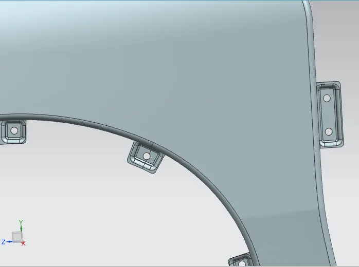
1. same select law extension command by using for Drip mounting frame creation as per mastic data .select the law extension command and pick the curve for initial frame and select the face of initial frame mention the value of length = 20mm and angle = 90deg and click ok.Now we have creat the datum plane in face of drip mounting .this area is tough with Apillar (Body).
2. Now create the sketch and embosed the sketch then trim the mounting Holes then create dart also because the mounting frame is so long.thats why we have create the drat its like a stiffner also in sheet metal surface . we have a make the face blend and edge blend in all sharp corners.
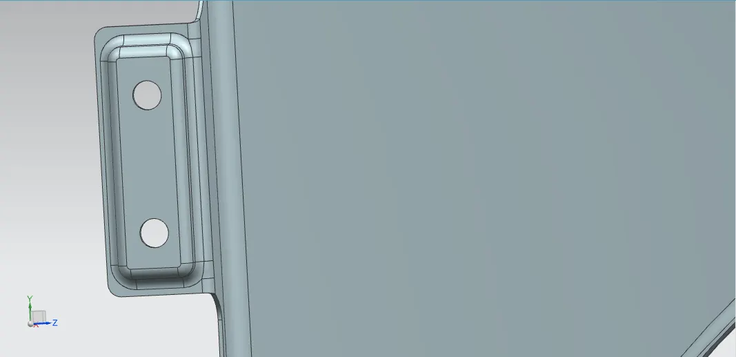
Sell Mounting:
1. select law extension command by using for Drip mounting frame creation as per mastic data .select the law extension command and pick the curve for initial frame and select the face of initial frame mention the value of length = 20mm and angle = 90deg and click ok.Now we have creat the datum plane in face of drip mounting .this area is tough with bottom frame of the car .
2. Now we have create the sketch and embosed the sketch then trim the mounting Holes then create dart also because the mounting frame is so long.thats why we have create the drat its like a stiffner also in sheet metal surface . we have a make the face blend and edge blend in all sharp corners.
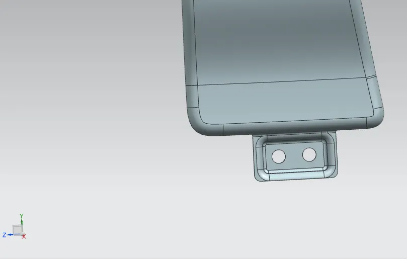
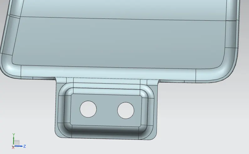
Baffle (Splash) Mounting:
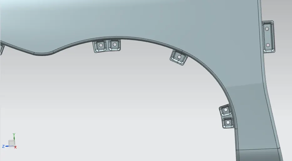
1. Three Mounting are create in this area .Becaus this is Wheel Arch Area. The Again select law extension command by using for Drip mounting frame creation as per mastic data .select the law extension command and pick the curve for initial frame and select the face of initial frame mention the value of length = 20mm and angle = 90 de and click ok.Now we have creat the datum plane in face of drip mounting .this area is tough with Engine compartment ad baffel of the car.
2. Again we have create the sketch and embosed the sketch then trim the mounting Holes then create dart also because the mounting frame is so long.thats why we have create the drat its like a stiffner also in sheet metal surface . we have a make the face blend and edge blend in all sharp corners.
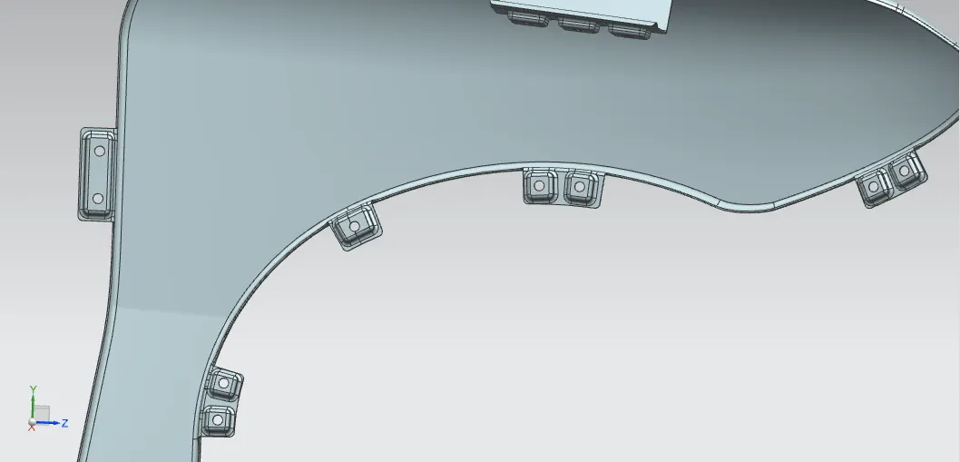
Fender Isometric View:
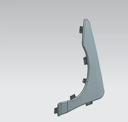
Fender Front view:
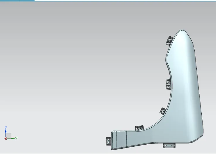
Fender Back View:
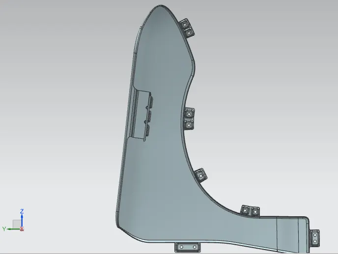
Fender Side View: