Fender Design
FENDER DESIGN PROJECT
To design the fender by designing drip area,bumper mounting,sill mounting,baffle mounting, A pillar mounting from the given master section and skin data.
so first create a assembly file and add the skin part of fender which is provided. and first we focus on creating the drip area in the given format from master section.
a flange is already given and from that we can integrate the new projections.
for that there is a standard dimentions from the position of a pillar (300mm or less), from the position of headlight area (150mm), that we must consider while aproaching the drip area.
so first create the a pillar mounting as in our design, and from the point of a pillar mount create a datum plain about 150mm to the headlight side and same is done from the headlight mount point about 150mm to the a pillar side. so we get to datum planes on the fender top.and create a intersection on the plane.this in between distance is for out drip area.
a 5mm offset is performed from the top corner of fender to the flange and from that offsetted curve we create the every mounting part.
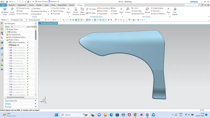
this is the skin data of fender given
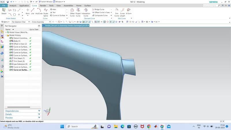
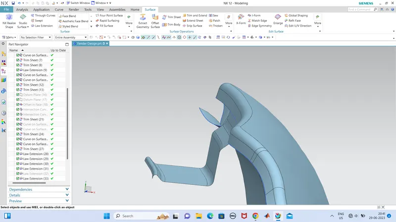
we just created this drip area as shown from the given dimensions .
we used to create this section using 'law extension' tool and appropriate angles.
and blended the edges using edge blend or face blend.
next we want to create the mounting holes,fore rigidity we provide emboss with the hole .so create emboss of 3 mm in the surface, by sketching in that same face plane,we can use datum plane on this surface to create sketch.and also create a hole of dia 5mm. and do emboss and trim the hole section from the sketch.
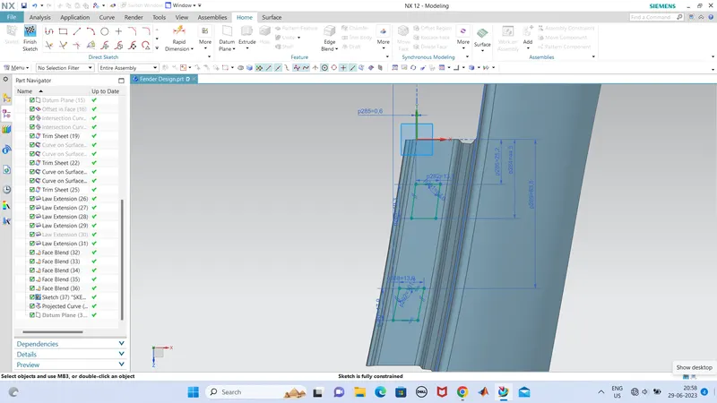
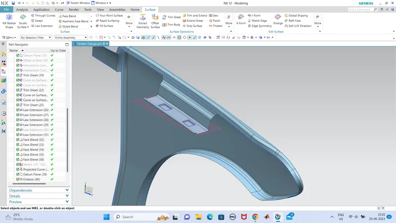
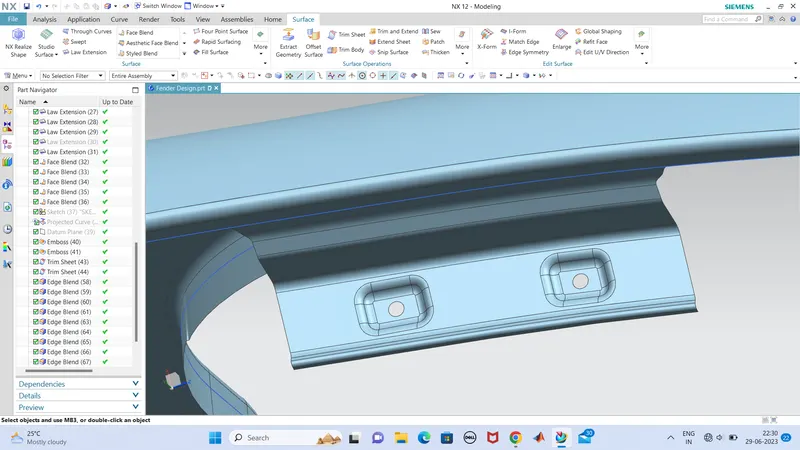
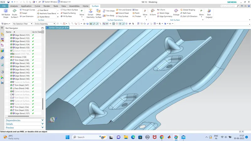
before doing edge blend, we provided dart to this portion for extra support and strength.
dart is done with two adjascent faces which is non linear and select the two faces and provide the values of dart, like, radius of dart,depth of dart,angle of dart.
edge blend is also provided to get a good finish.
so the drip area is created.
now we can move to the bumper mounting part,
the same thing is followed in each parts for creating.
so cut out a portion for bumper mounting ,which the dimentions are our own view of design. so i trimmed the portion for a good holding are to bumper.trimming is done by curve in face ,which can be done by our choise and aspects, provide same comntinuety at the two ends of curve so that its looks good.
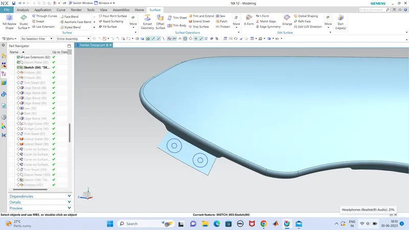
this is the portion for munper mount ,
first we done the law extension perpendicular to the flange, and given a length. and created a aketch in the datum plane which is in the same surface of this law extension surface.
then we can create the embosses, and trim the whole which the munper is supported to the fender by means of pins.
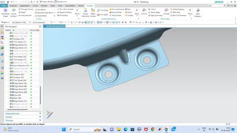
at the same time we also created a dart which gives more strength to the projected part.
dart is done with dart tool, which we want to select two non linear sufaces and provide the values of dart such as, angle of dart,depth,radius of dart.
so the bumper mounting is also done.
so we can create the flange surface for the mounting of mud flap.
we select the portions where we want the mounting and trim the unwanted flange area . in this section i extended the length of the selected area so that i gives more area to accomodate the mounting holes.
so,after the sketch is done in the plane where the face is situated, and emboss the sletch and trim the wholes for mounting plugs or pins.
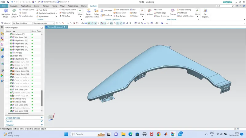
so the one flange is done in a proper manner, and another we need to done in the same way.
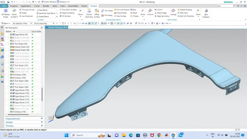
the sill area is shown in this figure, but we are describing in next step.
so the next part is sill mounting.,which is the lower part of fender which is fixed to the sill area of car.
so we extended the length of the selected flange area for sill mounting using 'law extension',or we can use 'extend sheet' as well.
and the same process is to be carried out in here also , that is, select the face and crate a datum plane on that face by simply clicking on the surface, and create the sketch for the mounting holes.
emboss the portion outer to the holes and trim the hole face .
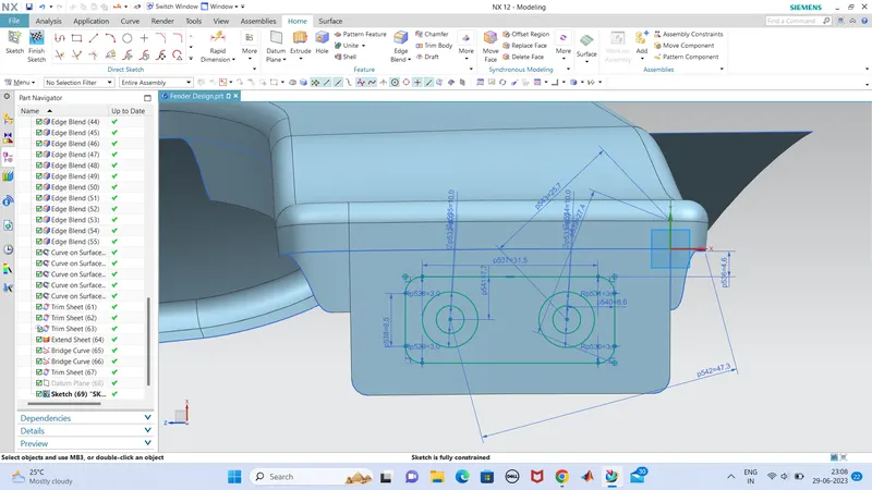
and provided the blends as well.
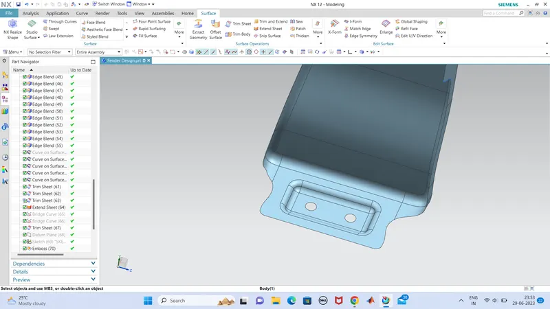
we provided the edge of the face to minimize the stress concentration so that we smoothen the edges.
so the sill area is also done created.
next is the a pillar mounting that we have created the face for mount,no we can create the sketch in that face by the slected datum on that face and sktech our own idea aspects.
so i done only one hole for the a clamp mouting which is shown below,
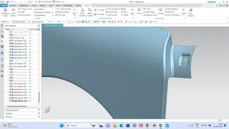
the process is same for all the mountings, that im not repeating again, so this is the 'A pillar' mount to which fender is mounted to the 'A pilar'.
blends are provided in all created corners for a smooth look and to reduce stress concentration.
CONCLUTION
so the design is done for fender and all the mounting parts are added to get rigid fix with components.