Fender Design
Fender:
Fender is a term used to describe the panel that covers the wheel well on a car. Fenders are typically made of steel, aluminum, or plastic and are designed to protect the wheel well from debris, water, and other elements that can cause damage to the vehicle.
Fenders play an important role in protecting pedestrians from injury in the event of a collision with a vehicle. When a vehicle collides with a pedestrian, the fender will be the first point of contact between the vehicle and the pedestrian. The fender can help to absorb some of the impact of the collision and prevent the pedestrian from being thrown onto the hood or windshield of the vehicle.
In addition to absorbing impact, fenders can also help to prevent debris and other objects from being thrown at pedestrians during a collision. This can help to reduce the severity of injuries sustained by pedestrians and prevent secondary injuries caused by flying debris.
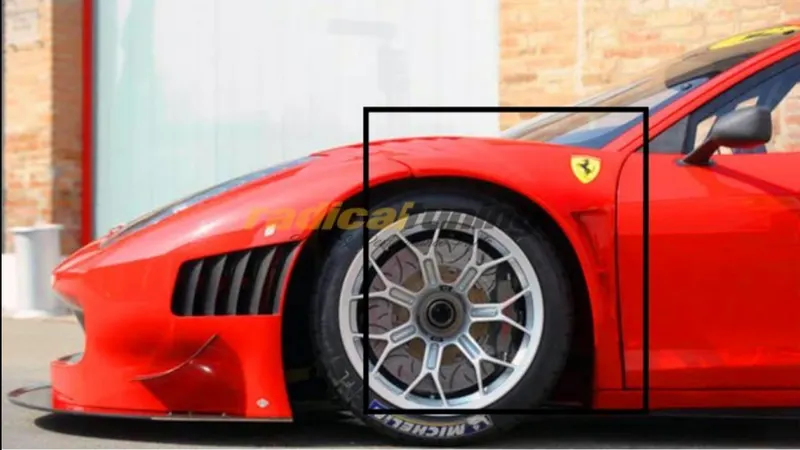
Types of Fender:
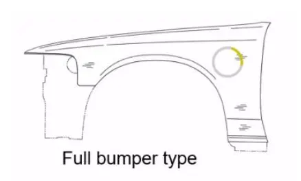
The full bumper type of fender is a traditional design that requires a higher amount of material compared to other types of fenders. This design was commonly used in older models of automobiles, but its use has decreased due to its impact on the vehicle's overall weight and performance. In addition, the full bumper type requires more maintenance due to its larger surface area.
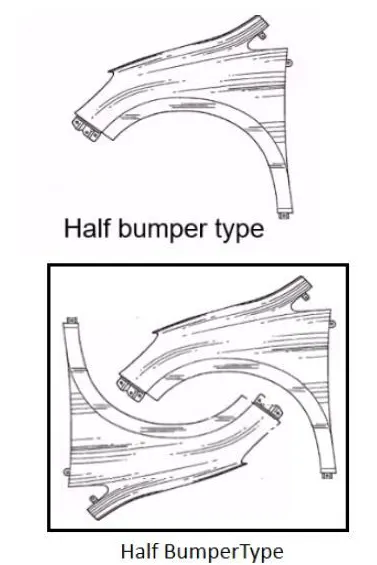
This is the type used on most modern cars. The half bumper type of fender is a modern design that requires less material compared to the traditional full bumper type. This reduction in material consumption increases productivity by allowing for a smaller blank size, which ultimately provides better vehicle performance. Additionally, the maintenance required for the half bumper type is comparatively lower than that of the full bumper type.The shift from the full bumper type to the half bumper type is primarily aimed at reducing the scrap rate per blank. With the full bumper type, only one fender can be produced per blank, whereas the half bumper type allows for the production of two fenders per blank, which increases efficiency and reduces waste.
Manufacturing of Fender:
The manufacturing process for fenders in cars involves sheet metal forming, which is a technique used to shape metal sheets into the desired form. Sheet metal forming typically involves the use of a press, which applies pressure to the metal sheet to shape it into the desired shape.
- The first step in the sheet metal forming process is to create a die, which is a tool used to shape the metal sheet. The die is typically made from hardened steel and is designed to create the desired shape of the fender.
- Once the die is created, the metal sheet is placed into a press and is subjected to high pressure to shape it into the desired form. The press may be hydraulic or mechanical, depending on the complexity of the fender's shape.
- The stamping process involves several stages, including blanking, bending, drawing, and trimming.
- During the blanking stage, the metal sheet is cut into the desired shape using the die.
- Next, the metal sheet is bent to create the appropriate angles and curves for the fender's shape.
- Drawing is then used to create the fender's depth, and trimming is used to remove any excess material.
- After the stamping process, the fender undergoes finishing processes, such as grinding, sanding, and polishing, to remove any imperfections or burrs that may have been created during the stamping process.
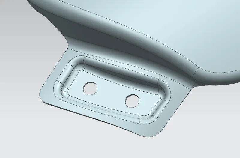
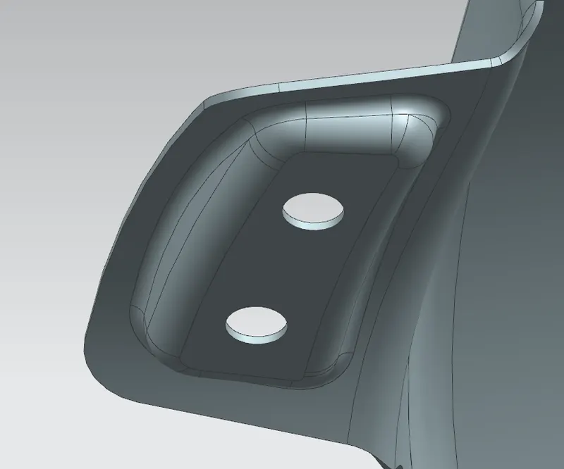
The assembly process involves mounting the fender onto the vehicle using various mounting points, such as the sill, drip area, baffle, A-pillar mounts, and bumper mounts. The fender is aligned with the rest of the vehicle's body and is secured in place using bolts or screws.
Design Criteria:
- The basic design criteria for a fender is to be congruent with the master section data (in our case, the drip area)
- There should be no sharp edges in the BIW
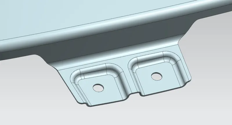
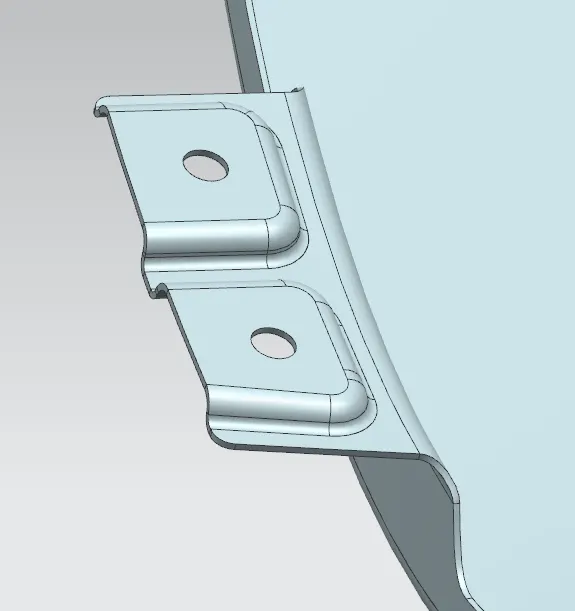
- The mounting area holes should have atleast 5mm of flat surface clearence
- The thickness of the BIW in our case is 0.75mm
- The embosses should be flat rather than curvilinear surfaces appeasing the ease for manufacturability as well as assembly
- Wheel Arch: The wheel arch for the given fender should be homologated (or should follow the standard regulations: USA, Japan, Europe)
- The provision of relief in areas of requirement which leads to decreased stress concentration
- Provision for tool accessibility to be considered
- For Drip Mounting Area: 150mm gap from the headlight region and less than or equal to 300mm from the A-Pillar mounting region (unless specified)
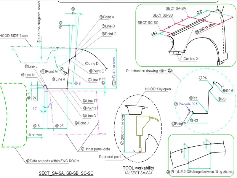
Fig: Master Section data for Drip area Mounting
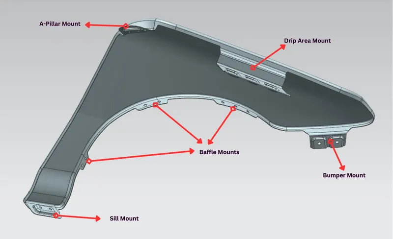
Fig: Fender with it's mounting areas
Mounting Area Creation (General):
- The use of offset curve in face command to created the trimming regions alongside the mount regions
- Using curve in surface to create smoothe transition for the mounting area to the main surface
- Trimming the non-required area to get the mounting regions
- Using face blends according to master section provided for the Drip area as well as using 3mm radius face blends for the rest.
- Creation of sketches for the mounting holes as well as embosses to be projected on the respective surface
- Using embosses wherever required (it's mostly function of the aesthetics in our case as the dimensioning data is't given for them; albeit shouldn't be too small or big)
- Creation of the mounting holes with the 5mm flat clearence criteria
- Trimming all the sharp corner using the bridge curves as tools.
Sill Area Mount
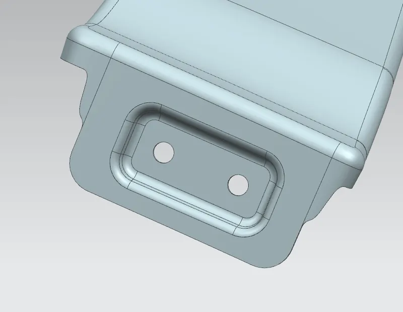
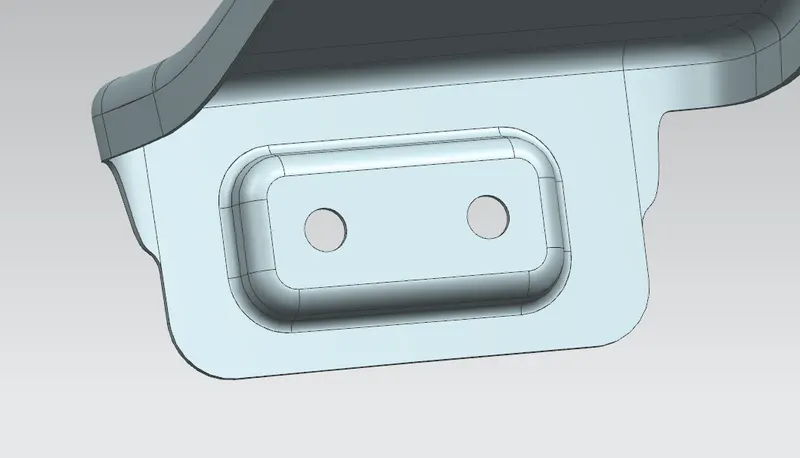
Drip Area Mount
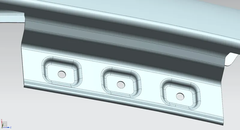
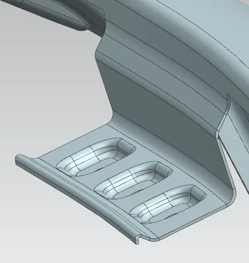
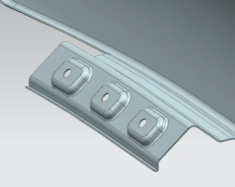
Bumper Area Mount
 .
.
Baffle Area Mounts
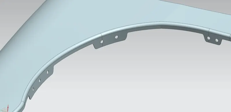
A-Pillar Mount