Fender Design
AIM : To create our own design according to the Engineering standards for the Sill, Bumper, Baffle(Splash), and A-Pillar mount .
FENDER
Fender is the american english term for the part of an automobile, motorcycle or other vehicle body that frames a wheel well. Its primary propose is to prevent sand, rocks, mud, liquids, and other road spray from being thrown into the air by the rotating tire. Fender are typically rigid and can be damaged by contact with the road surface.Sticly materials, such as mud, may adhere to the smooth outer tire surface, while smooth loose objects, such as stones, can be become temporarily embedded in the tread grooves as the tire rolls over the ground. These materials can be ejected from the surface of the tire at high velocity as the tire imparts kinetic energy to the attached objects. For a vehicle moving forward, the top of the trie is rotating upward and forward, and can throw objects into the air at other vehicle or pedestrians in front of the vehicle. Fender is a front outer side member of a car, which covers the wheel side. It has so many small features with ups and downs.
It is an aesthetic component/part of a car that frames the wheels. Prevention of sand, mud particles, and other road contaminants from being thrown into the engine compartment and also to the pedestrians by the rotating tires are the main purpose served by the fenders.
The front fenders are separate components whereas the rear fenders are integrated with the body sides.
TYPES OF FENDERS
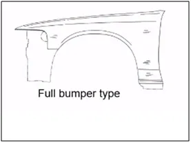
1. FULL BUMPER TYPE: These types of fenders were used in earlier models of vehicles. They contribute to the major increment of the steel weight by just covering the front headlights with respect to the bumper region. The problem associated with this kind of fender is there is a lot of wastage in the blank and every inch of a Material is a cost to the industry.
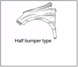
2. HALF BUMPER TYPE: These fenders are mainly used for serving the purpose of cost-cutting and reducing enough proportions of the steel wait resulting in a reduction of the weight of the vehicle slightly. They can be economically manufactured, i.e by slightly increasing the blank size, we can produce two fenders at a time.
Different Mountings on Fender :
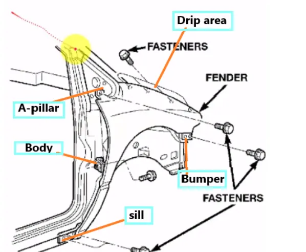
There are 5 mountings on the Fender , they are
- A- pillar mounting
- Body mounting
- Sill mounting
- Bumper mounting
- Drip mounting
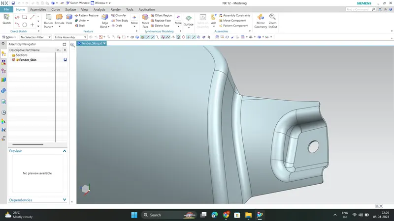
DESIGN OF BUMPER MOUNTING AREA :
Bumper mounting area is used to fix the plastic bumper to the fender with the help of the fasteners
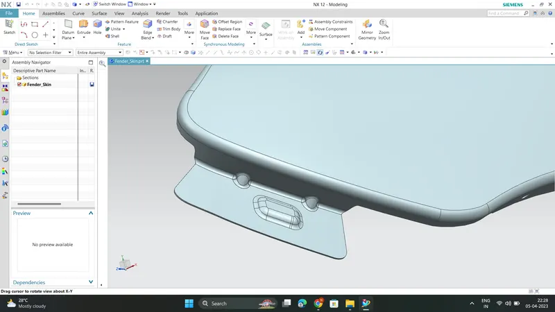
DESIGN OF A-PILLAR MOUNTING AREA :
The A -pillar is the structural pillar that combines the body to the roof . this make the sides of the windshield rest .
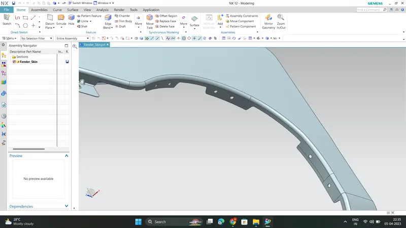
DESIGN OF BAFFLE MOUNTING AREA :
Baffle mounting or mudguard are clip fit type of mounting on the inner side of the fender arch over the Tyre.
It protects the car engine compartment and pedestrians from causing injuries from chip out debris on the road when the car is in motion .
They are mounted on the fender using a special type of locking clips which are made up of plastics .
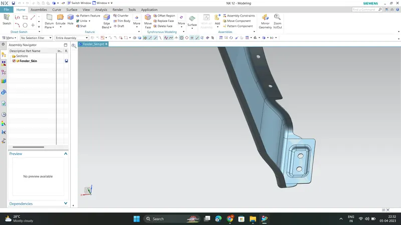
DESIGN OF SILL MOUNTING AREA :
Sill is the panel directly below the bottom of the door supporting the floor and may be used to combine the floor and the body .
The bottom end of the fender is mounted on the sill body for reinforcement of the fender panel , thus the sill mounting position
is designed with holes and emboss . M5 fasteners are used to fix the fenders on the sill body.
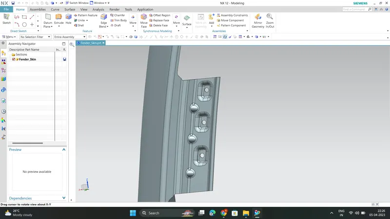
DESIGN OF DRIP AREA MOUNTING :
- It is the important mounting unit of the fender . it is connected with the engine compartment , therefore the lot of design constraints are to be followed while designing the fender
- While designing the drip area we have to initially leave 200-300 mm for cowl top
- For placing the headlamp we have to leave at least 150 mm at the front while designing the fender
- Cowl top part consists pf wiper motor and its instruments
- Two darts are added on the longer side of the drip area in order to provide the stiffness and adds strength to the part . This helps the fender to not to vibrate and impact the forces outside of the fender during motion of the vehicle.
- Embossing are provided on the mounting to strengthen them during fastening.
Commands used from NX CAD to model this fender are:
- Offset in face
- Curve on surface
- Trim sheet
- Law extension
- Datum plane
- Intersection curves
- Face blend
- Bridge curve
- Sketch
- Projected curve
- Emboss
- Edge blend
- Sew
- Dart
- Thicken
After creation of all different Mounting points on the Fender , the thickness of 0.75 mm is added inward on the final sewed surface of the fender to the sheet metal parameters .
Manufacturing Processes :
The manufacturing of the fender majorly involves these operations .
1.Embossing
2.Bending
3.Cutting and Blanking
4.Stamping
Embossing
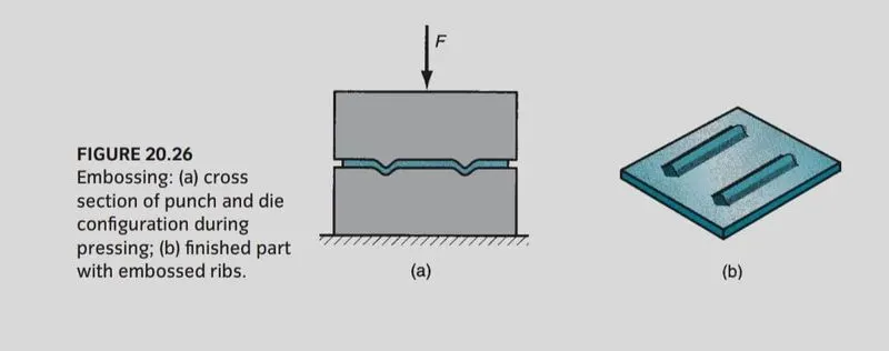
Embossing Embossing is a metal forming process for producing raised or sunken designs or relief in sheet material using matched male and female roller dies, theoretically with no change in metal thickness, or by passing sheet or a strip of metal between rolls of the desired pattern.
Bending
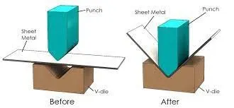
Metal bending is a process by which metal can be deformed when applying force to the subject, which causes it to bend at an angle and form the anticipated shape, which often results in it being in a 'V' or a 'U' shape. This is done through the application of force on a workpiece. The force on the work piece can be mechanical, pneumatic or hydraulic
Cutting and Blanking
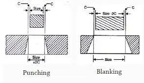
Cutting processes are those in which a piece of sheet metal is separated by applying a great enough shearing force to cause the materialto fail. Blanking is a steel manufacturing process in which a flat, geometric shape is created by feeding a coil of sheet metal into a press and die in this process, the blank is punched out from the large metal sheet.
Stamping
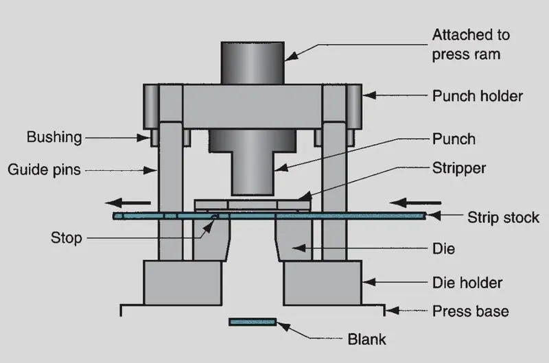
The working components are the punch and die, which perform the cutting operation. They are attached to the upper and lower portions of the die set, respectively called the punch holder(or upper shoe) and
die holder (lower shoe). The die set also includes guide pins and bushings to ensure proper alignment between the punch and die during the stamping operation. The die holder is attached to the base of the press, and the punch holder is attached to the ram.Actuation of the ram accomplishes the pressworking operation. In addition to these components, a die used for blanking or hole-punching must include
a means of preventing the sheet metal from sticking to the punch when it is retracted upward after the operation. The newly created hole in the stock is the same size as the punch, and it
tends to cling to the punch on its withdrawal. The device in the die that strips the sheet metal from the punch is called a stripper.
For dies that process strips or coils of sheetmetal, a deviceis required to stop the sheet metal as it advances through the die between press cycles. That device is called
a stop. Stops range from simple solid pins located in the path of the strip to block its forward motion, to more complex mechanisms synchronized to rise and retract with the actuation of
the press.