Fender Design
- TABLE OF CONTENT:
- OBJECTIVES
- DEFINITIONS
- MANUFACTURING PROCESS
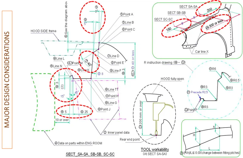
- DESIGN CONSIDERATIONS
- DESIGNING USING SIEMENS NX TOOL (STEPS, SNIPS, AND RESULTS)
- CONCLUSION
- OBJECTIVE:
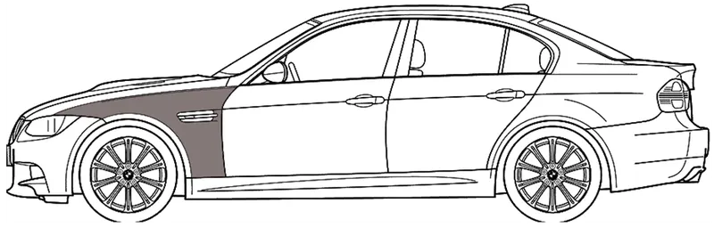
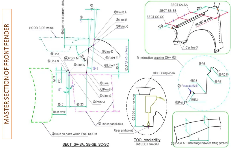
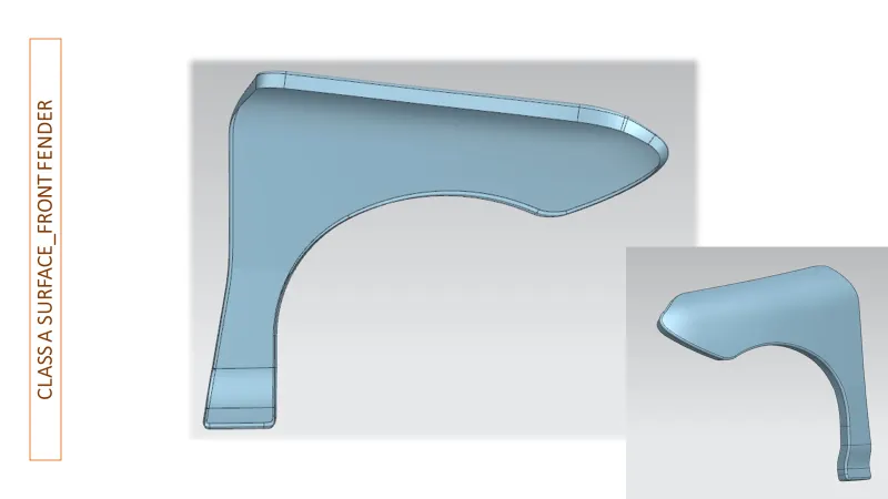
To design a Front Fender of a car by following the given master section and applying engineering features as per the design considerations of OEM.
FENDER:
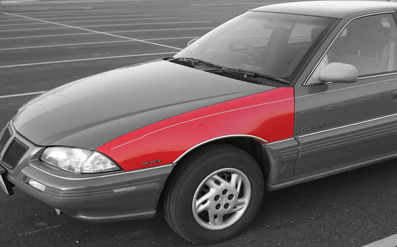
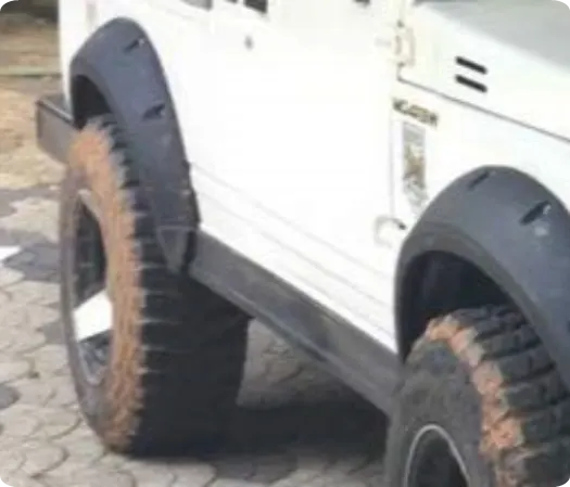
The fender is the body that frames a wheel well (the fender underside). Its primary purpose is to prevent sand, mud, rocks, liquids, and another road spray from being thrown into the air by the rotating tire. Fenders are typically rigid and can be damaged by contact with the road surface.
- Sticky materials, such as mud, may adhere to the smooth outer tire surface, while smooth loose objects, such as stones, can become temporarily embedded in the tread grooves as the tire rolls over the ground. These materials can be ejected from the surface of the tire at high velocity as the tire imparts kinetic energy to the attached objects. For a vehicle moving forward, the top of the tire is rotating upward and forward and can throw objects into the air at other vehicles or pedestrians in front of the vehicle.
- In British English, the fender is called the wing. (This may refer to either the front or rear fenders. However, in modern unibody vehicles, rear fenders may also be called quarter panels). The equivalent component of a motorcycle, or the "cycle wing" style of wing fitted to vintage cars, or over tires on lorries which is not integral with the bodywork, is called a mudguard in Britain, as it guards other road users – and in the case of a bicycle or motorcycle, the rider as well – from mud.
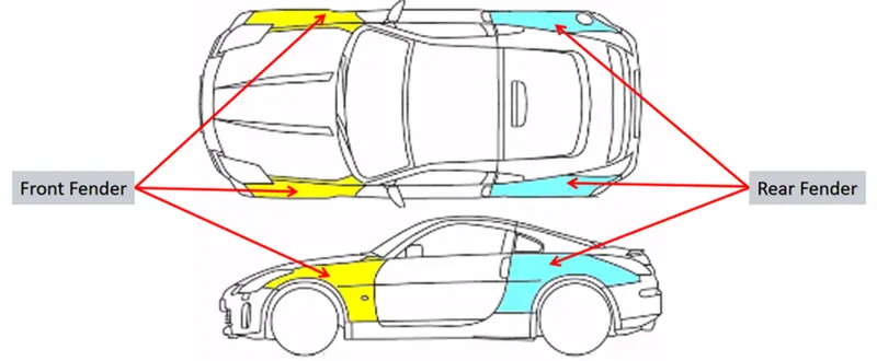
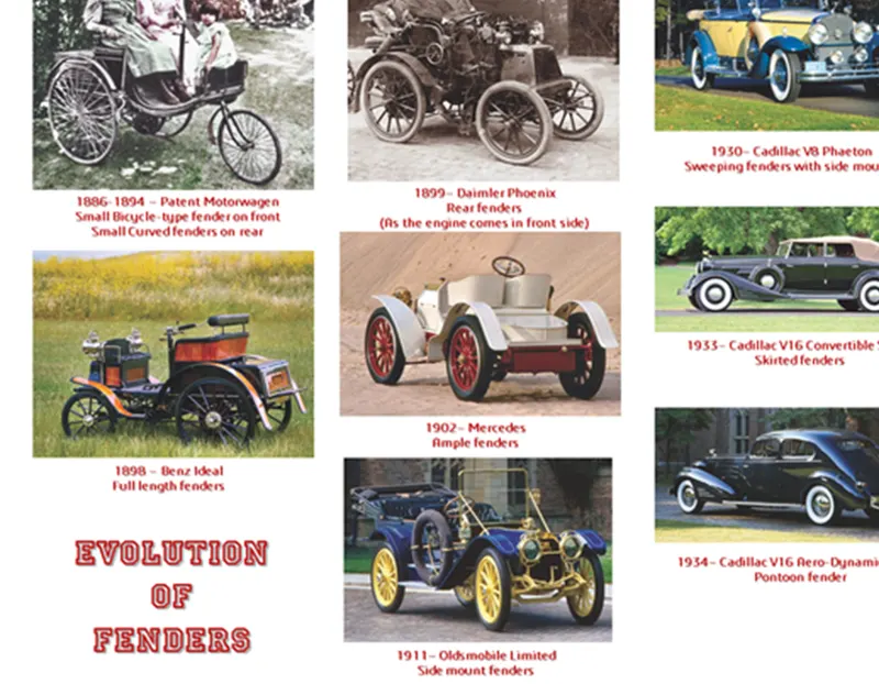
Fenders nowadays came in a more integrated form compared to old vehicles, as the old vehicle’s fenders had a pronounced appearance. Old vehicles, especially from the 1950s, had a unique flair and style, with most of them featuring bubble fenders that stuck out prominently. Modern fenders have evolved a lot with time in comparison to old ones because they not only serve an aesthetic purpose but play an important role in enhancing the aerodynamics of the vehicle. Furthermore, modern fenders are engineered to absorb impact from minor collisions as well. They have a fender liner attached to them that protects the engine bay and other components from potential damage that can be caused by rocks and flying debris.
Why is it called a Fender…?
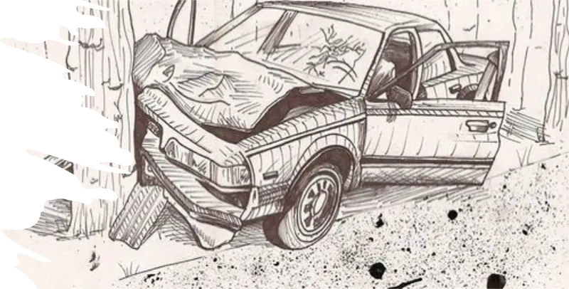
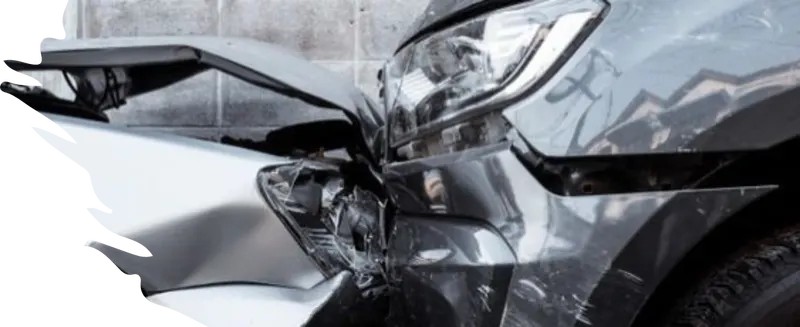
Because it “fends off” other things colliding with a car: other cars, animals, fire hydrants, Batmobiles, whatever…and takes the damage upon itself to save damage to the rest of the car.
Purpose of Fender :
- Cleanliness: Protect the car, occupants, and passers-by from items, water, mud, snow, and ice, thrown off the tires as you drive.
- Safety: Protects pedestrians from the wheel, e.g., it's better to be it by a laterally moving fender than a rolling tire, and keeps loose, streaming items from being wrapped up in a rolling wheel.
- Aerodynamics: Smooths the car profile so you don't get a lot of drag off the uncovered wheels. Some fenders are enclosed on the side for this.
- General Appearance: Looks better with fender, gives a finished look, looks more streamlined

TYPES:
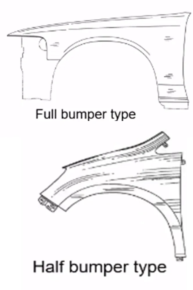
Typically, Fenders have 2 types,
1. Full Bumper Type: The Fender extends to a semi-circle, this design is not much cost-effective, and the manufacturing wastage was more, so to improve it, the Half bumper type is being introduced.
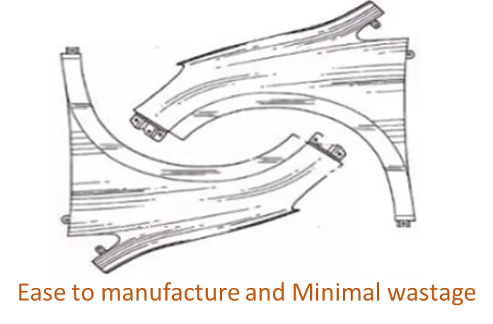
2. Half Bumper type: This is the Evolved/ Improvised design from the Full Bumper type where here the Fender is Quarter the circle which was cost-effective since the wastage during production was nominal.
FENDER MANUFACTURING PROCESS
The manufacturing of the fender majorly involves these operations.
- Embossing
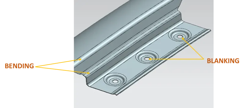
- Bending
- Cutting and Blanking
- Embossing
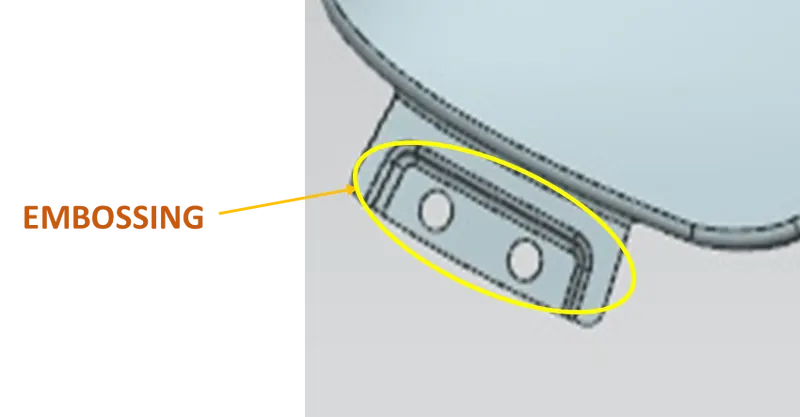
Embossing is a metal forming process for producing raised or sunken designs or relief in sheet metal using matched male and female roller dies, theoretically with no change in metal thickness, or by passing a sheet or a strip of metal between rolls of the desired pattern.
Bending
Metal bending is a process by which metal can be deformed when applying force to the subject, which causes it to bend at an angle and form the anticipated shape, which often results in it being in a 'V' or a 'U' shape. This is done through the application of force on a workpiece. The force on the workpiece can be mechanical, pneumatic, or hydraulic
Cutting and Blanking
Cutting processes are those in which a piece of sheet metal is separated by applying a great enough shearing force to cause the material to fail. Blanking is a steel manufacturing process in which a flat, geometric shape is created by feeding a coil of sheet metal into a press and die in this process, the blank is punched out from the large metal sheet.


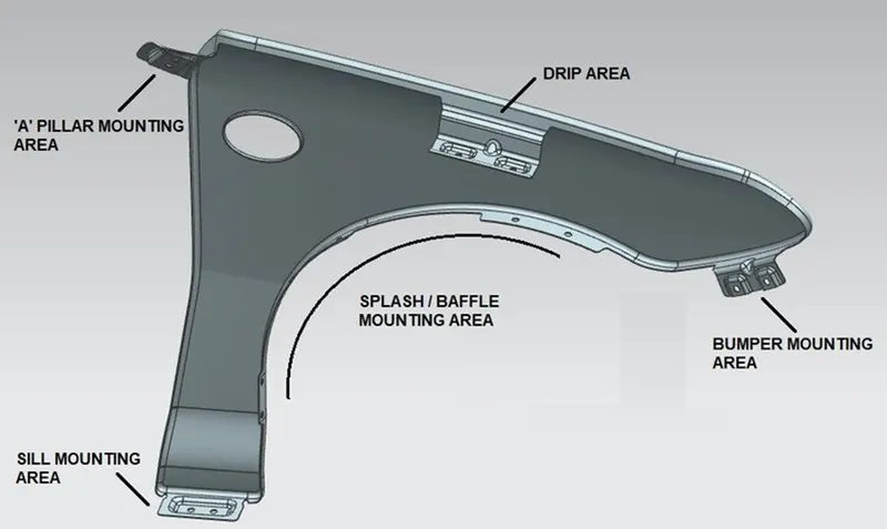
MOUNTING PROVISIONS
1. Bumper
2. Drip
3.A-Pillar
4. Sill
5. Cowl/ Baffle
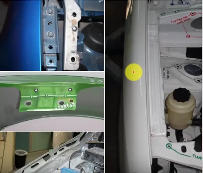
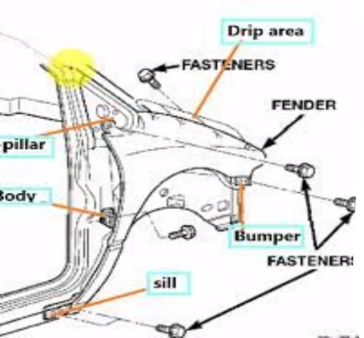
DESIGN OF DRIP AREA MOUNTING :
- It is the important mounting unit of the fender. It is mounted with the engine compartment; therefore, a lot of design constraints are to be followed while designing the fender.
- While designing the drip area we have to initially leave 200-300 mm for the cowl top in general.
- For placing the headlamp, we have to leave at least 150 mm at the front while designing the fender.
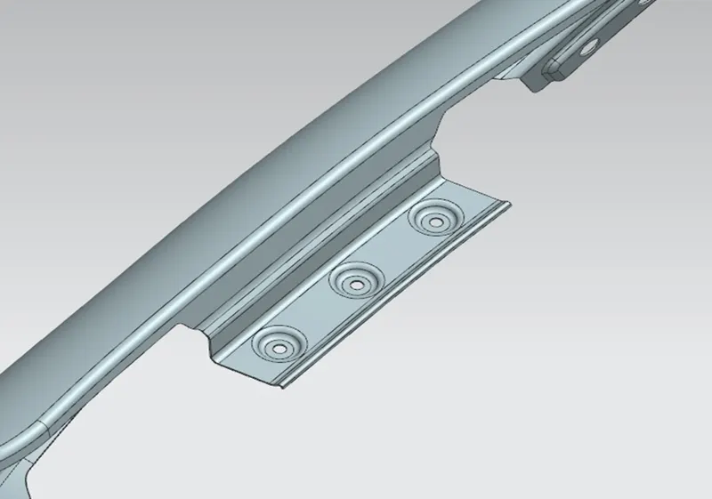
- Cowl top part consists of wiper motor and its instruments
- Two darts are added on the longer side of the drip area in order to provide stiffness and add strength to the part. This helps the fender not to vibrate and impact the forces outside of the fender during the motion of the vehicle.
- Embosses are provided on the mounting to strengthen them during fastening.
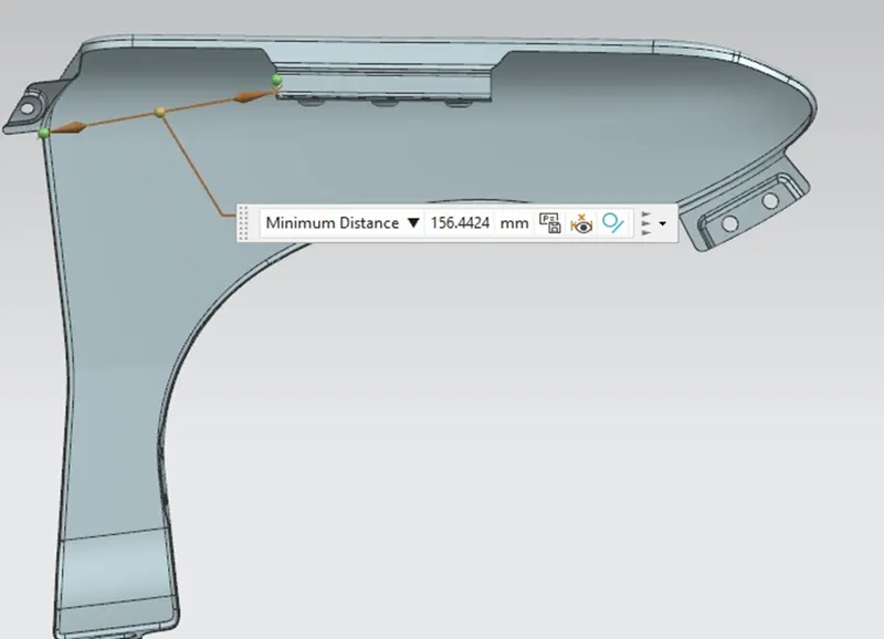
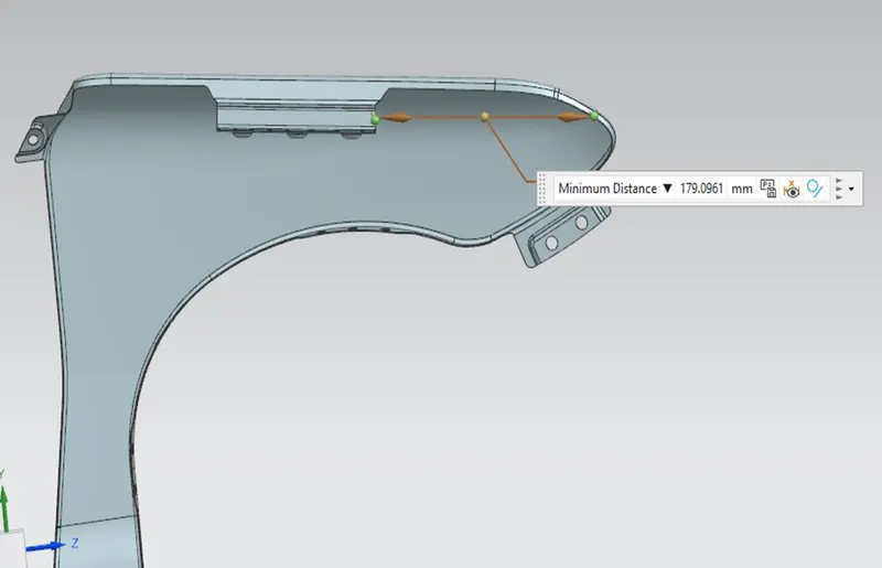
DESIGN OF SILL MOUNTING AREA :
Sill is the panel directly below the bottom of the door supporting the floor and may be used to combine the floor and the body. The bottom end of the fender is mounted on the sill body for reinforcement of the fender panel, thus the sill mounting position is designed with holes and emboss.
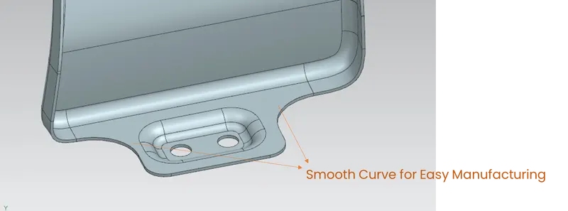
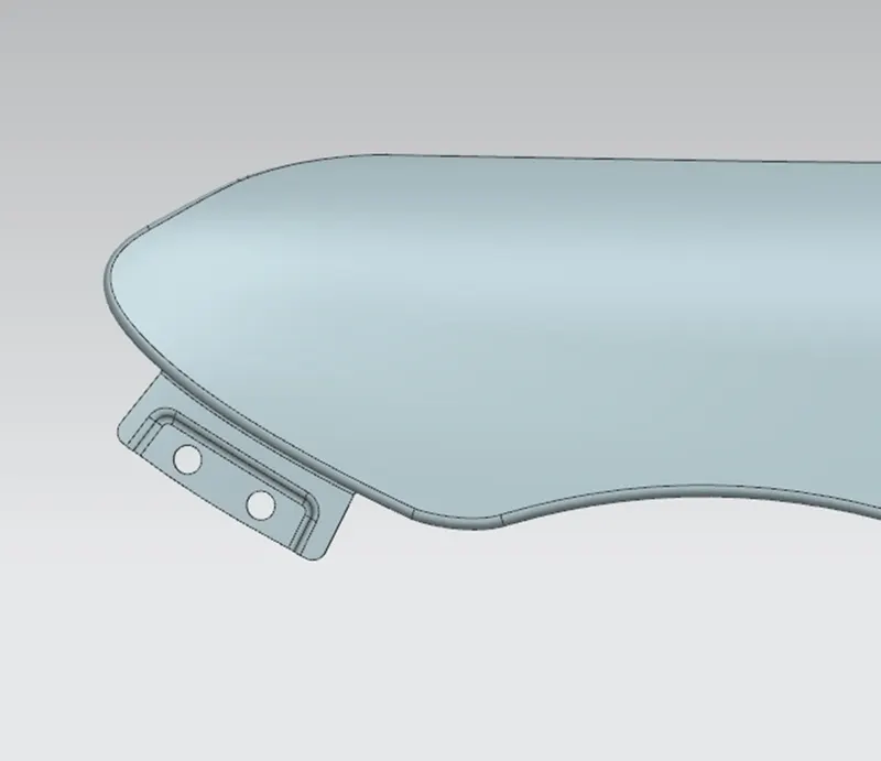
DESIGN OF BUMPER MOUNTING AREA :
The bumper mounting area is used to fix the plastic bumper to the fender with the help of the fasteners
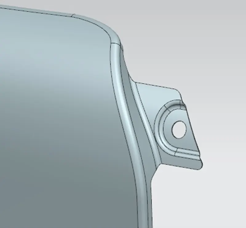
DESIGN OF A-PILLAR MOUNTING AREA :
The A-pillar is the structural pillar that combines the body with the roof. This makes the sides of the windshield rest. front fenders are fastened to the A-pillar to form a robust structure.
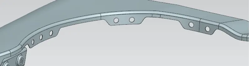
DESIGN OF BAFFLE MOUNTING AREA :
Baffle mounting or mudguard are clipping fit types of mounting on the inner side of the fender arch over the Tire. it protects the car engine compartment and pedestrians from causing injuries from chip-out debris on the road when the car is in motion. they are mounted on the fender using a special type of locking clips which is made up of plastic.
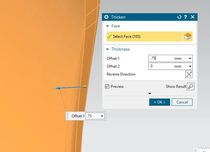
THICKENING.
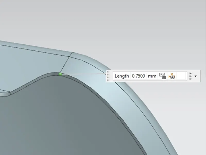
The thickness of 0.75 mm inward on the final sewed surface of the fender is applied to form the sheet metal.
FINAL PRODUCT_ VIEWS
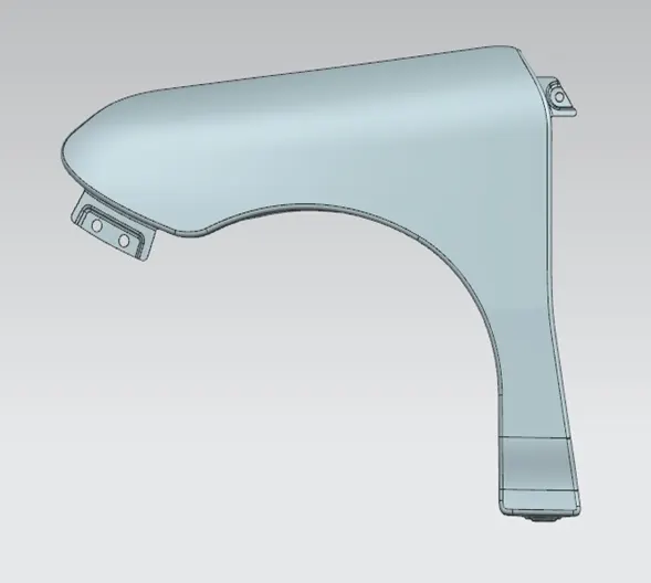
FRONT VIEW
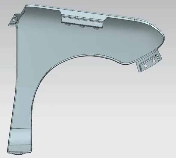
REAR VIEW
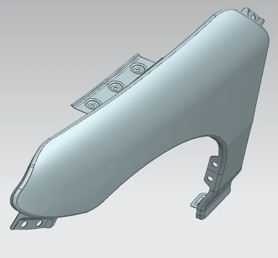
ISOMETRIC VIEW
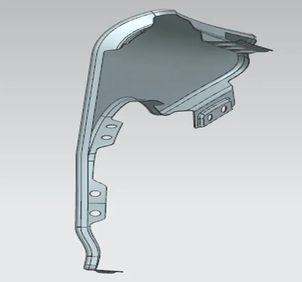
RIGHT SIDE VIEW
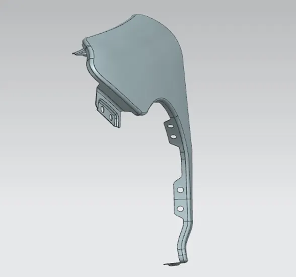
LEFT SIDE VIEW
- CONCLUSION:
Hence, we have successfully completed our Fender design by following all the standards and considering the given input Fender skin and Master section.