Fender Design
Objective
To Desgin a fender from the class A surafce and create Drip area, A-pillar mounting,Sill and Bumper mounting.
Software used
NX CAD
Introduction
Fender
Fender is the American English term for the part of an automobile, motor cycle or other vechiles body that frames a wheel well (the fender underside). Its primary purpose is to prevent sand, mud, rocks, liquids, and other road from being thrown into the air by the rotating tire. Fenders are typically rigid and can be damaged by contact with the road surface.
Sticky materials, such as mud, may adhere to the smooth outer tire surface, while smooth loose objects, such as stones, can become temporarily embedded in the tread grooves as the tire rolls over the ground. These materials can be ejected from the surface of the tire at high velocity as the tire imparts kinetic energy to the attached objects. For a vehicle moving forward, the top of the tire is rotating upward and forward, and can throw objects into the air at other vehicles or pedestrians in front of the vehicle.
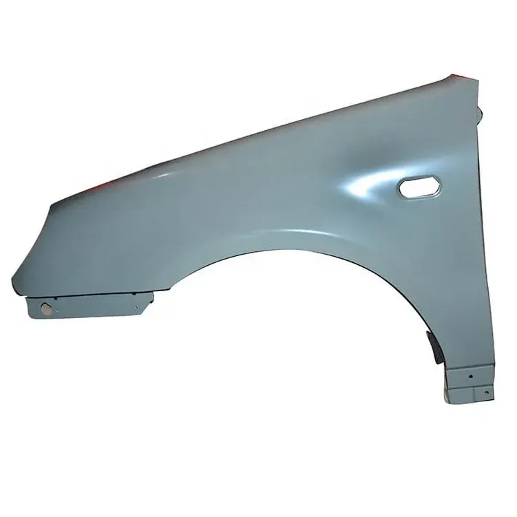
There are two variants of fender
1. Full Fender
2.Half Fender
Below is the image fender modeled in nx cad
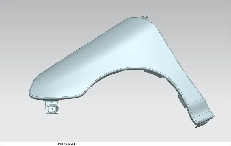
Fender Mount's
1. A pillar mount
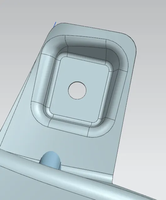
2. Bumper Mount
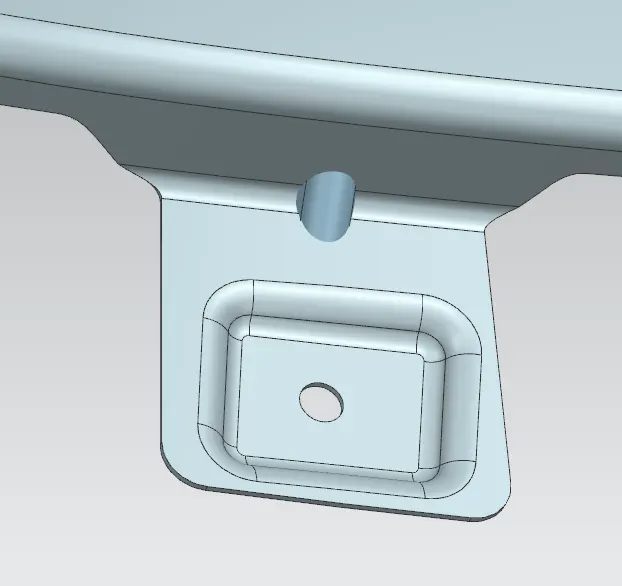
3 Drip area
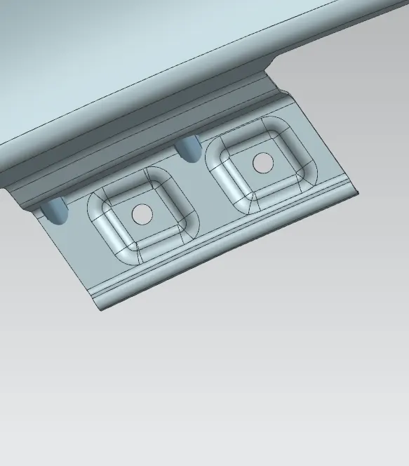
4. Baffel Splash
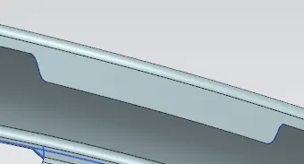
5. Sill mount
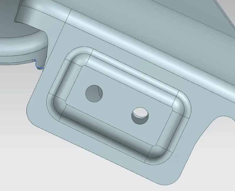
Manufactring processe invoved
1. Piercing
2. Drawing
1. Piercing
Piercing is a shearing process in which raw metal is pierced with a machining tool, resulting in the creation of a circular or other shaped hole. As the raw metal is pierced, the metal from the newly created hole is considered scrap.
2. Drawing
Drawing is a metalworking process that uses tensile forces to elongate metal, glass, or plastic. As the material is drawn (pulled), it stretches and becomes thinner, achieving a desired shape and thickness. Drawing is classified into two types: sheet metal drawing and wire, bar, and tube drawing.