Fender Design
A Report on Fender Design and its Types:
Fender is a part of automobile body which is mounted above the wheels. The main function of the fender is to reduce the damages on the parts of automobile body due to mud, stone and debries that were seen in roads. Due to the rotation of the wheels the debries are thrown in and out of the wheels which leads to damage if there is no fender used in the automobile body.
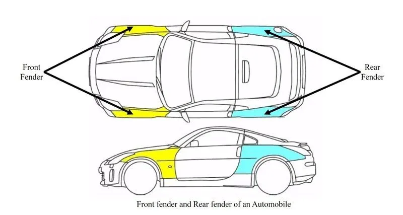
Fender also protects the other vehicles and the people who were near to the moving automobile. Fender that used in automobile is categorised into two types, front and back fender.
Front Fender:
The name itself indicates that this type is mounted above the front wheels of the automobile. It is placed inbetween the bumper and front door of the body. Front fender is of two types based on the design constraints, they are full fender and half fender.
The full and half fender can be understand easily by the below shown image.

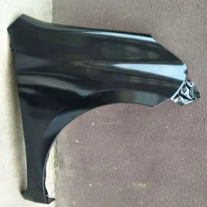
Full Fender Half Fender
In olden days the full fender were used which occupies more area and material cost is also high due large size compared to half fender. Thus to overcome the cost cuttings, design improvements, aesthetic looks the half fender came into market and widely used all over the models.
Front Fender Mountings:
Front fender is mounted by fasteners at the mounting areas in the automobile body. They are listed below:
- Baffle Mounting Area
- A pillar
- Sill
- Bumper
- Drip (Engine compartment)
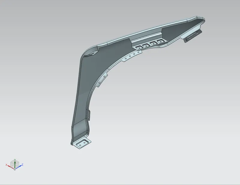
The below image shows the 3D model of fender done in NX Cad Software.
Baffle Mounting Area:
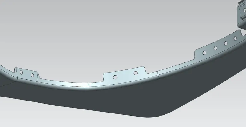
The above image shows the position on where the baffle are mounted. Baffle are made up of polymer materials. They are mounted with the fender by mounting clips. The baffle are used mainly to reduce the NHV rates.
A-pillar:
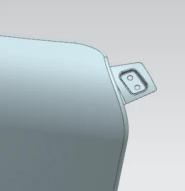
This image shows the A-pillar mounting area which is located near the cowl area which hold the wiper motor.
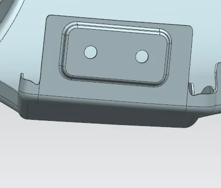
Sill Mounting Area:
This image shows the Sill mounting area which comes near the bottom of the front door.
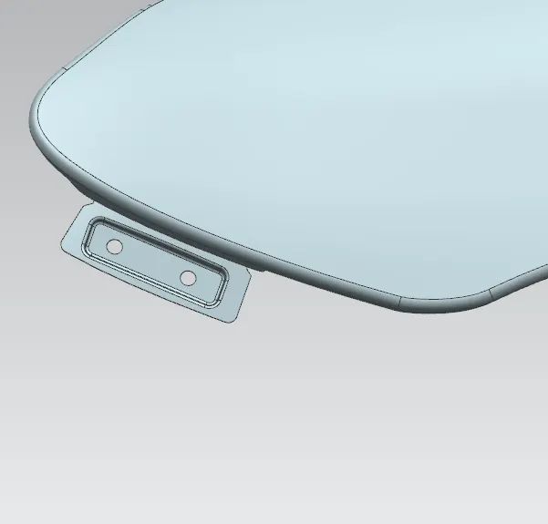
Bumper Mounting Area:
This mounting area is provide at the back of the bumper which get mounted with the bumper.
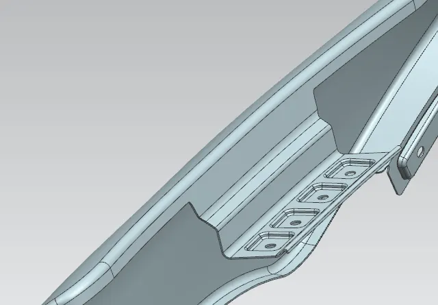
Drip Area:
This area is used to attach the fender near the engine compartment. Designing of this mounting area is one of the major consideration because the locating of drip area plays an important role in maintaing the quality and productivity of the fender.
Back Fender:
The back fender are seen above the rear wheels of the automobiles. It is mostly fixed with the body by welding. It lies inbetween the backdoor and bonnet. The below image shows the back fender used in toyota brand car.
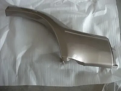
Fender used in the automobiles are made up of plastic, fiber, aluminimum and other materials also. The material selection is based upon the model and specification of the car.
Manufacturing Process:
The process used in manufacturing the fender is the punching of the sheet with the dies at high pressure of about 1000 tonnes approximately acts on the sheet used for manfacturing the fender. The steps involved are:
- The sheet of required size is been cut out from the sheet roll.
- Then the cutted sheet is placed in the Stamping pressing machine which hold the die for the shape on which the fender needs to be manufactured.
- Then the machine is operated to punch the sheet between the die with high pressure.
- Thus a fender of required shape is attained by this process.
- The pressed sheet of the fender shape is then processed by the hemming process to remove sharp corners at the edges.
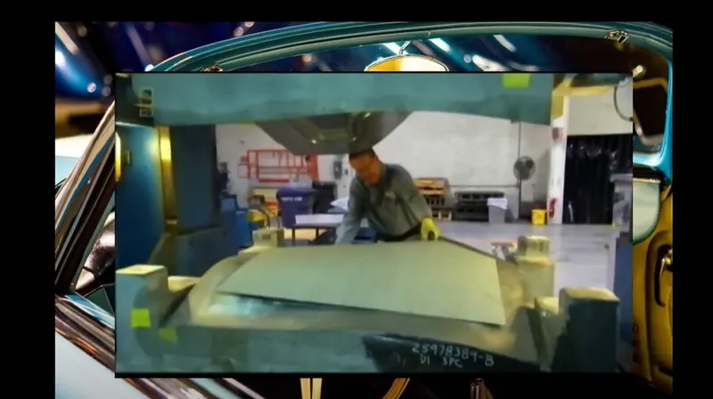
The below shown images can give a clear view of Stamping process done for fender manufacturing.
1. Die used in the stamping machine.
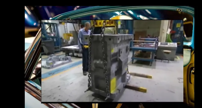
2. The blank taken from cold rolled sheet for manufacturing the fender and placing it in the stamp pressing machine.
3. The below image shows one of the type stamp pressing machine on how it looks.
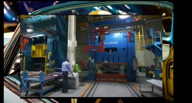
4. The die approaching the blank which is feeded in the machine.
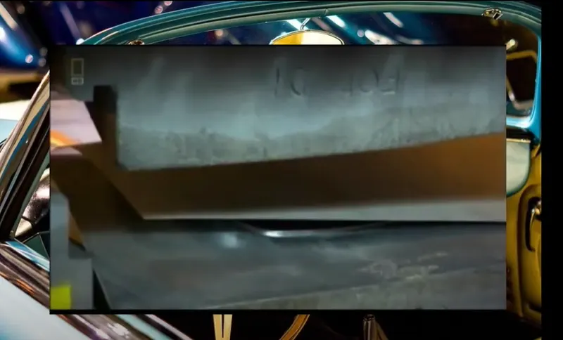
5. After the die hits the blank and once the pressing is completed, the formed fender can be observed from the below image.
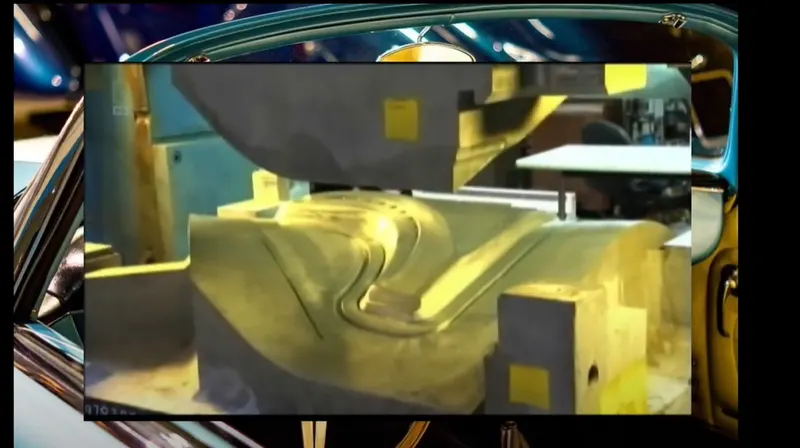
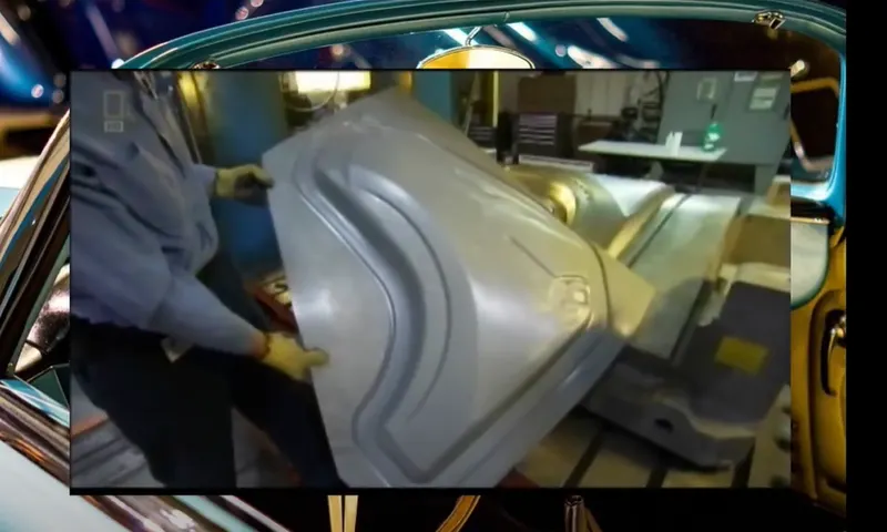
6. Thus the required fender is been taken as a result from stamp press in the machine. Then this will be transfered to machining area for creating holes, then hemming is done to remove sharp edges.
Desgin Constrains:
The commonly followed design parameters in front fender are:
- The gap between the front head lamp and the drip area front point is to maintain about 150mm.
- The minimum gap between the drip area back point to the A-pillar mounting is to be within 300mm.
- The radius for fillets in fender design is about minimum of 2.5mm to be maintained.
- The sharp edges needed to removed by providing relief areas.
- The darts (stiffners) needed to be provide at the drip areas and also in other areas where the length of stamped sheet is more to improve the strength.
- The profiles of the fender should be maintained of smooth transcition.
- The drip mounting area height needed to designed in a manner to avoid the spring back effect.
- The mounting holes should have a flat area for contact.
- The embosses created about 5-10mm distace from the edges will be of good for reducing the strains.
- The draft angles should be provided and maintained of above 7 degree for increasing the tool life.
Apart from safety consideration the fender also plays an important role in aerodynamics design parameter. Fenders improve the aerodynamics of the vehicle. As the tires rotate at high speed, they cause a lot of drag by creating turbulence around them. A curved enclosure of a fender over the wheels helps to reduce that turbulence and improve the aerodynamics of the car.
Conclusion:
This report provides a basic information about the fender design and its parameters commonly used in the industries.